Weld distortion is a permanent change in a welded part’s shape or dimensions caused by uneven heating and cooling. As you weld, the hot metal expands, the surrounding cooler metal restrains it, and the joint shrinks as it solidifies and cools. That movement can leave residual stress behind and pull the part into angular distortion, bowing, buckling, transverse shrinkage, or warping. Heat input, joint design, material thickness, fit-up, restraint, and weld sequence all affect the final result. When you understand those variables before you strike an arc, you can reduce movement, protect accuracy, and avoid expensive rework.
Quick Answer
Weld distortion happens when localized weld heat makes metal expand and then shrink unevenly as it cools. You reduce it by using good fit-up, smaller welds where allowed, balanced welding sequences, proper tacking, controlled heat input, clamps or fixtures, and careful cooling instead of long uncontrolled beads.
Key Takeaways
- Weld distortion is caused by uneven expansion, contraction, and restraint around the weld zone.
- The main forms include longitudinal shrinkage, transverse shrinkage, angular distortion, bowing, buckling, and warping.
- High heat input, poor fit-up, large weld beads, thin metal, asymmetrical joints, and weak fixturing increase distortion risk.
- You control distortion best before welding by planning the sequence, using tack welds, clamping correctly, and balancing heat.
- Correcting distortion requires care. Structural, pressure, lifting, or vehicle-frame welds should be checked against an approved procedure or inspected by a qualified professional.
At a Glance
| Time Required | 10–30 minutes of planning and setup for small jobs; longer for structural or multi-part assemblies |
| Difficulty | Beginner to intermediate for basic control; advanced for structural correction or heat straightening |
| Tools Needed | Clamps, tack welds, square, straightedge, tape measure, feeler gauges, fixtures, heat-resistant gloves, helmet, ventilation, and fire protection |
| Cost | Often $0–$50 if you already own clamps and layout tools; higher if you need fixtures, heat-treatment service, or professional inspection |
What Is Weld Distortion?
Weld distortion, also called welding deformation, is the unwanted change in a workpiece’s shape or dimensions during or after welding. It happens because welding heats one area much more than the surrounding base metal. That hot area expands, then shrinks as the weld solidifies and cools.
You may see the result as a pulled joint, bowed plate, twisted frame, shortened seam, buckled sheet, or angle that no longer matches the drawing. The part may still be welded, but the final geometry can be outside tolerance.
Weld distortion is not just a cosmetic issue. If the part no longer fits, seals, aligns, or carries load correctly, the weld has created a dimensional problem that must be controlled or corrected.
The key idea is simple: metal moves when heat is uneven. The more uneven the heat, shrinkage, and restraint, the more the workpiece wants to move. That is why distortion control starts before welding, not after the part is already warped.
Distortion is different from porosity, cracking, or lack of fusion. Those are weld defects inside or along the weld. Distortion is a shape-control problem, although both can happen on the same job. If you are also troubleshooting weld soundness, understanding the causes of porosity can help you separate weld contamination problems from movement problems.
How Weld Distortion Happens
Weld distortion happens in three connected stages: heating, restraint, and cooling shrinkage.
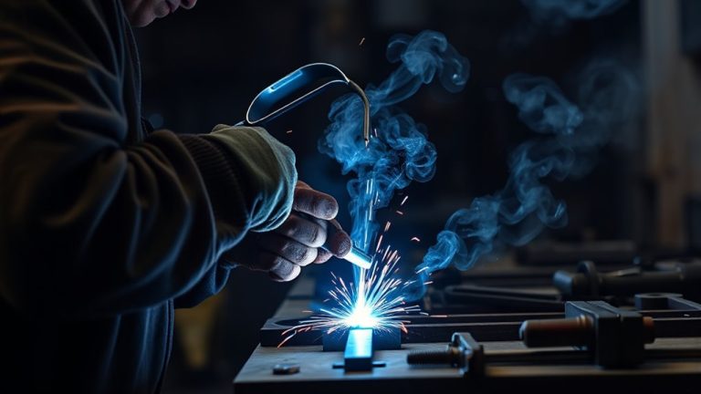
First, the arc or flame heats a narrow zone near the joint. That metal tries to expand. The cooler surrounding base metal resists the movement, so stress builds around the weld zone. Then the weld pool solidifies and contracts. Finally, the heated area continues to shrink as it returns toward room temperature.
The exact amount of shrinkage depends on the metal, weld size, joint design, heat input, and restraint. For example, steel and aluminum do not expand, conduct heat, or shrink in the same way. That is why one fixed shrinkage percentage is not safe for every welding job.
You also have to account for weld pool shape. A wide, slow, high-heat bead puts more hot metal into the joint and spreads heat farther into the base metal. A smaller controlled bead usually creates less shrinkage force, as long as it still meets the strength and penetration requirements of the job.
Note: Distortion and residual stress are related, but they are not the same. Distortion is visible movement or shape change. Residual stress is stress that remains locked inside the part after welding, even if the part looks straight.
Cooling rate matters too. Fast, uneven cooling can sharpen temperature differences across the joint. Slow, uncontrolled heat buildup can also create problems because it allows a larger area to expand and shrink. Your goal is not simply to make the weld hot or cold. Your goal is to make heat input, heat balance, and shrinkage predictable.
Material properties also matter. If you want a broader foundation on how weld process choices affect material behavior, this overview of the advantages and disadvantages of welding can help you compare trade-offs.
Main Types of Weld Distortion
The main types of weld distortion are longitudinal shrinkage, transverse shrinkage, angular distortion, bowing, buckling, and warping. These forms can appear alone, but they often overlap on real projects.
For example, a long fillet weld can shorten along the seam and also pull the joint angle inward. Thin sheet can buckle while a thicker frame member mainly bows. Knowing the type of movement helps you choose the right prevention or correction method.
Longitudinal Shrinkage
Longitudinal shrinkage happens when the weld contracts along the length of the seam. The workpiece can become slightly shorter or pull out of alignment along the weld direction.
You will see this most clearly on long seams, lightly restrained parts, or assemblies where one side receives more weld metal than the other. Tack welds, balanced weld placement, and accurate layout marks help limit this movement.
| Factor | Impact |
|---|---|
| Long continuous seam | More accumulated shrinkage along the weld direction |
| Poor tacking | Parts can creep before the final weld locks them in |
| Balanced sequence | Helps spread shrinkage forces more evenly |
Transverse Shrinkage
Transverse shrinkage pulls across the width of the joint, perpendicular to the weld seam. Butt welds often show this as a narrower gap after welding, pulled edges, or a panel that no longer matches the planned width.
This type of distortion gets worse when the root gap is too wide, the bevel is oversized, or the weld deposit is larger than needed. Good fit-up, the correct groove angle, and a weld size that matches the design requirement help control it.
Angular Distortion
Angular distortion occurs when one side of a joint shrinks more than the other and changes the angle between parts. It is common in fillet welds, T-joints, lap joints, and beveled butt joints where the weld is not balanced through the thickness.
- Unequal heating drives the angle change.
- Large weld beads increase shrinkage force.
- Asymmetrical joints pull more in one direction.
- Poor fit-up makes the joint easier to pull out of square.
- Alternating sides and balanced passes reduce the effect.
Angular distortion can slow assembly, force grinding or rework, and make the part hard to bolt, fit, or seal. Check the angle after tacking and again after the first short welds so you can adjust before the part is fully locked in.
Buckling and Warping
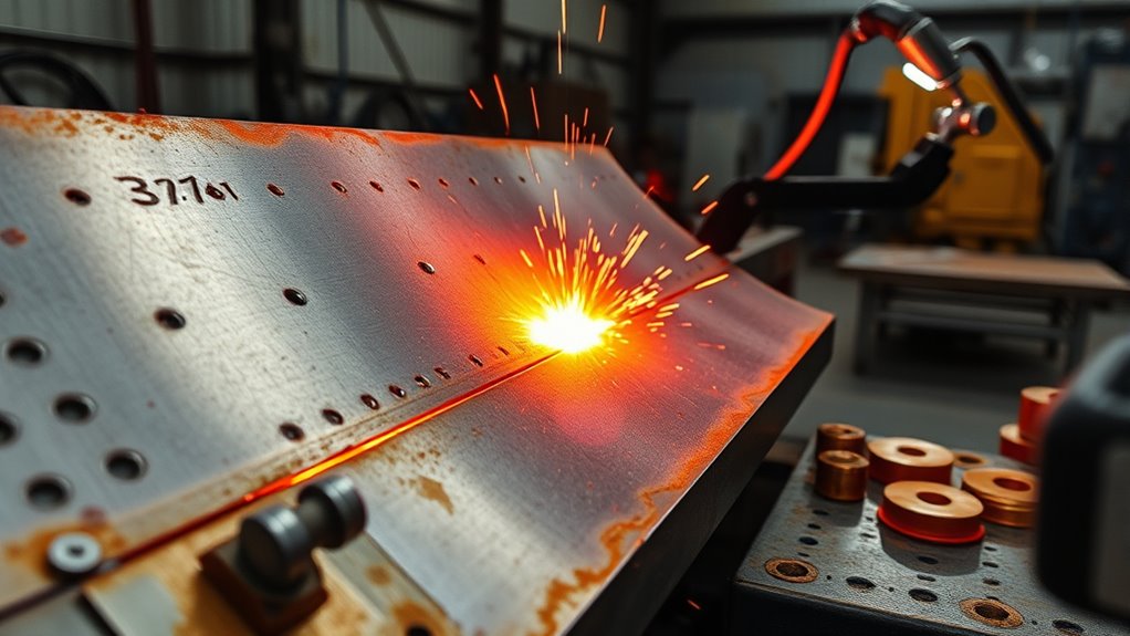
Buckling happens when thin or lightly supported metal cannot resist the compressive stress created during welding. Instead of staying flat, the sheet or plate pops out of plane.
Warping is a broader term for bending, twisting, or waviness caused by uneven heating and cooling. It is common on thin sheet metal, wide panels, long flat bars, and parts with uneven thickness.
You reduce buckling and warping by supporting the work, using shorter welds, allowing controlled cooling, and avoiding excessive heat input. Clamps and fixtures help, but they should not be used as a substitute for poor fit-up or oversized welds.
Pro Tip: On thin sheet, make several short welds spaced apart instead of one long bead. Let the panel cool between welds and move around the joint so heat does not collect in one area.
Why Weld Distortion Happens
You see weld distortion when localized heating makes metal expand and then shrink unevenly during cooling. The weld zone, heat-affected zone, and surrounding base metal do not all reach the same temperature at the same time.
Those temperature differences create thermal gradients. When one area wants to move and another area holds it back, stress builds. If the stress exceeds what the material can elastically absorb, the part changes shape permanently.
Heat input, weld size, travel speed, joint geometry, material thickness, restraint, and cooling conditions all influence the result. Proper heat input control is especially important on thin metal because small changes in technique can create visible warping.
Thermal Expansion and Shrinkage
Thermal expansion and shrinkage are the core physics behind weld distortion. The metal near the weld expands when heated. As it cools, it contracts. If that contraction is uneven or restrained, the joint pulls out of shape.
- Expansion pushes hot metal outward.
- The cooler base metal restrains that movement.
- The weld pool shrinks as it solidifies.
- The heated zone contracts further as it cools.
- Different metals expand and conduct heat at different rates.
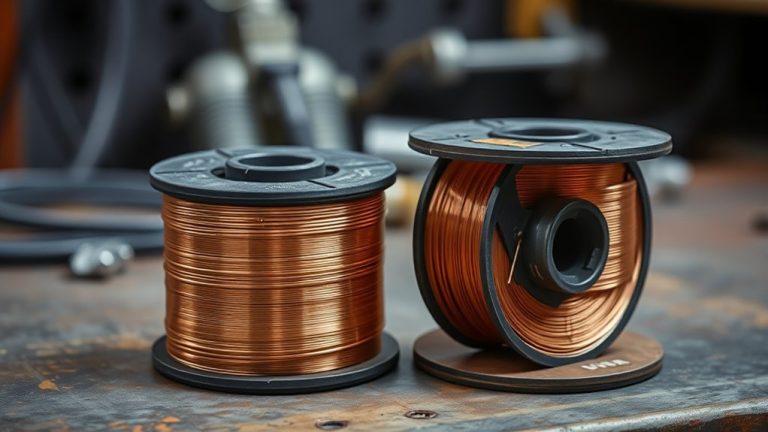
Dissimilar metals, high-carbon steels, and aluminum alloys can be more demanding because their thermal behavior and weldability differ. Use the correct filler, procedure, preheat, and cooling approach for the specific material.
Uneven Heat Distribution
Uneven heat distribution happens when one part of the assembly absorbs or releases heat differently from another. Thick sections heat and cool differently than thin sections. Wide gaps need more filler metal. Large bevels require more weld deposit. Drafts can cool one side faster than the other.
Asymmetrical joint designs also steer heat unevenly. A weld placed on only one side of a joint pulls more strongly toward that side. A balanced joint, or a sequence that alternates sides, gives the shrinkage forces a better chance to cancel each other.
If preheating or post-weld heat treatment is required for the material or code, follow the correct procedure. Do not guess. Incorrect heating can reduce properties, create cracks, or make distortion worse.
Residual Stress Build-Up
Residual stress is stress that remains in the welded part after the weld cools. It can exist even when the part looks straight. In some cases, later machining, cutting, grinding, or service loading releases that stress and the part moves.
- Local heating changes dimensions.
- Cooling contraction pulls on the weld and heat-affected zone.
- Weld metal and base metal may respond differently.
- Rigid restraint can lock stress into the assembly.
- Later cutting or machining can release that stress.
Managing residual stress means controlling the weld procedure, heat input, fit-up, restraint, and cooling path. For critical work, stress relief may require an approved heat-treatment procedure rather than shop-floor guesswork.
How Heat Input Changes Distortion Risk
Heat input directly affects distortion risk because it controls how much metal expands, how wide the heated zone becomes, and how much shrinkage force develops as the joint cools. In arc welding, heat input is influenced by voltage, amperage, travel speed, process efficiency, wire or electrode size, bead size, and technique.
Higher amperage, slower travel speed, wide weave beads, and oversized filler deposits usually add more heat to the part. That can increase shrinkage and warping if the joint is not designed or restrained well. Smaller stringer beads, correct travel speed, and proper weld sizing help keep the heated zone tighter.
This does not mean you should under-weld the joint. A weld still needs enough fusion, penetration, and size for the job. The goal is to use the minimum heat that produces a sound weld that meets the requirement.
Long continuous welds can build heat and pull a part hard in one direction. Shorter controlled welds, skip welding, backstep welding, and alternating sides often work better for distortion control. Using techniques from FCAW and GMAW can help when you need steady deposition, but the settings and sequence still matter.
| Heat-input factor | Distortion effect | Better control method |
|---|---|---|
| Slow travel speed | Adds more heat per inch | Use a steady travel speed that still gives proper fusion |
| Oversized bead | Adds extra shrinkage force | Match weld size to the design requirement |
| Long continuous pass | Pulls the joint in one direction | Use skip, backstep, or alternating welds when suitable |
| Poor cooling control | Creates uneven contraction | Shield from drafts and follow the required cooling procedure |
Why Joint Design Matters
Joint design plays a major role in distortion control because the joint shape controls where weld metal goes, where heat flows, and how shrinkage forces act. A poor design can make distortion almost unavoidable, even if your welding technique is good.
Balanced geometry helps shrinkage act more evenly. Proper fit-up and alignment reduce gaps that require extra filler metal. A smaller groove angle, where allowed by the procedure, can reduce weld volume and shrinkage. Correct root opening and land dimensions help the joint weld properly without adding unnecessary heat.
- Joint symmetry reduces uneven shrinkage.
- Accurate fit-up limits stress concentrations.
- Aligned parts contract more predictably.
- Correct weld size reduces unnecessary filler metal.
- Balanced joints improve heat control.
You cannot eliminate distortion by simply welding “hotter” or adding more metal. You reduce it by designing and fitting joints so the weld has less reason to pull. Understanding the importance of amperage for penetration can help you avoid both under-fusion and excessive heat input.
Why Some Metals Distort More
Some metals distort more than others because their expansion rate, thermal conductivity, strength, thickness, and prior stress history are different. When you choose a metal, you are also choosing how it reacts to weld heat.
Thin stock moves easily because it has less stiffness. Aluminum conducts heat quickly and expands more than steel, so it can move fast if the setup is not controlled. High-carbon and hardenable steels may need preheat or controlled cooling to reduce cracking risk and stress problems. Stainless steel can distort noticeably because it conducts heat more slowly than carbon steel and can hold heat near the weld zone.
| Material or condition | Why it can distort | Control tip |
|---|---|---|
| Thin sheet metal | Low stiffness and fast heat response | Use short welds, cooling pauses, and strong backing support |
| Aluminum | High thermal conductivity and expansion | Use clean fit-up, correct filler, and controlled heat |
| Stainless steel | Heat stays concentrated near the weld | Use low heat input and avoid overwelding |
| High-carbon steel | Stress and cooling rate can raise cracking risk | Follow proper preheat and cooling guidance |
| Parts with residual stress | Machining, forming, or prior welding may release movement | Plan sequence and inspect after cutting or welding |
Asymmetrical joints and wide gaps intensify mismatch between parts. Understanding the maximum fillet weld size is useful because overwelding a fillet can add heat and shrinkage without adding useful strength.
How to Minimize Weld Distortion
To minimize weld distortion, control how heat enters the workpiece, how shrinkage forces are balanced, and how the part is held while cooling. The best results come from planning, not from trying to force the part straight after it has moved.
Start with accurate joint preparation. Clean the metal, remove heavy rust or coatings, check the gap, and confirm the parts are square before tacking. Removing heavy rust before welding also helps reduce contamination and weld-quality problems.
- Plan the sequence. Decide where each tack and weld will go before you start.
- Improve fit-up. Tight, even fit-up needs less filler metal and less heat.
- Tack correctly. Use enough tack welds to hold alignment without creating hard restraint points that crack.
- Clamp and fixture the part. Support the work so it cannot sag, twist, or pull freely.
- Use the right weld size. Do not make a larger weld than the design requires.
- Balance the welds. Alternate sides, weld from the center outward, or stagger passes when suitable.
- Control heat input. Use proper settings, steady travel speed, and shorter weld segments where needed.
- Check as you go. Measure alignment after tacking and between weld passes.
Warning: Welding creates fire, burn, fume, UV, and electrical hazards. Use proper PPE, ventilation, and fire protection. For structural, pressure, lifting, vehicle-frame, or code-governed welds, follow the approved welding procedure and get qualified inspection when required.
Preheating can reduce sharp temperature differences on some materials, but it is not always needed and can be harmful if done incorrectly. Post-weld heat treatment can relieve residual stress on certain jobs, but it must match the material and procedure.
Weld Sequence Techniques That Help Control Distortion
Weld sequence is one of the most useful distortion-control tools because it controls where shrinkage happens first and how each weld pulls against the next one.
- Backstep welding: Weld short segments in the opposite direction of overall progress. Each segment shrinks against the previous one and helps limit continuous pull.
- Skip welding: Weld separated sections first, then return to fill the gaps after cooling. This spreads heat across the part.
- Alternating sides: Move from one side of the joint to the other so shrinkage forces stay more balanced.
- Center-out welding: Start near the center and work outward so movement is divided instead of pushed to one end.
- Balanced multi-pass welding: Place passes evenly around the joint instead of stacking all heat on one side.
The best sequence depends on part shape, thickness, access, and weld requirement. For simple shop projects, the most important rule is to avoid putting all the heat in one area before the rest of the assembly is stabilized.
How to Measure Weld Distortion
You cannot control what you do not measure. Check distortion before, during, and after welding so you know whether the part is still within tolerance.
| Tool | What it checks |
|---|---|
| Straightedge | Bowing, waviness, and panel flatness |
| Square or angle gauge | Angular distortion and out-of-square joints |
| Tape measure or calipers | Length, width, and diagonal measurements |
| Feeler gauges | Gaps under a straightedge or fixture contact points |
| Dial indicator | Small movement on precision parts |
Record key dimensions before welding. On frames, check diagonals after tacking. On panels, check flatness after each short weld group. If movement starts early, adjust the sequence before the full weld locks the distortion in place.
Which Welding Processes Reduce Distortion?
The welding process can affect distortion, but no process removes distortion by itself. Distortion depends on heat input, weld size, travel speed, restraint, material, and sequence.
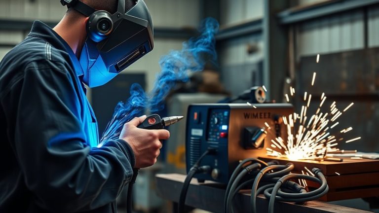
Processes that give consistent control can help. Pulsed MIG, controlled short-circuit MIG, TIG with careful heat control, laser welding, resistance spot welding, and friction stir welding can all reduce distortion in the right application. Automated and semi-automatic systems can also help because they keep travel speed and deposition more consistent than uneven manual technique.
For common shop work, MIG and TIG can both produce low-distortion results when the joint is clean, fitted well, and welded in short controlled segments. Flux-core can be useful on thicker or outdoor work, but it can add heat quickly if settings and travel speed are not controlled.
The process should match the job. Do not choose a low-heat method if it cannot produce proper fusion. Also make sure coatings are handled safely. If you are welding galvanized steel, ensuring that zinc residues are removed before welding helps reduce fumes and contamination risk.
How to Fix Weld Distortion Safely
You can sometimes correct weld distortion, but repair should be controlled and measured. Do not keep heating or bending the part blindly. You can overcorrect, crack the weld, weaken the material, or hide a deeper quality problem.
- Mechanical straightening: Uses clamps, presses, jacks, or fixtures to bring the part back into position. Use slow, measured force.
- Controlled heat straightening: Uses small heated zones to create planned shrinkage. This requires skill and should be avoided on critical parts unless the procedure allows it.
- Stress relief: Uses approved thermal treatment to reduce residual stress on suitable materials and applications.
- Cut and rework: Sometimes the safest fix is to remove the weld, improve fit-up, and weld again with a better sequence.
- Professional inspection: Needed for structural, pressure, lifting, vehicle-frame, or safety-critical parts.
If the part is cracked, severely buckled, or part of a load-bearing assembly, treat distortion as a quality issue, not just a cosmetic flaw. Inspect the weld before deciding how to straighten it.
Frequently Asked Questions
How do you fix welding distortion?
You can fix welding distortion with mechanical straightening, controlled heat straightening, stress relief, or rework. Start by measuring the part and identifying the distortion type. Use slow, controlled correction and inspect the weld afterward. For structural or code-governed work, use a qualified procedure or inspector.
What are the main causes of weld distortion?
The main causes are uneven heating, uneven cooling, weld shrinkage, excessive heat input, oversized welds, poor fit-up, weak restraint, asymmetrical joint design, and a poor weld sequence. Thin metal and metals with high thermal expansion are more likely to move.
What are the three most common types of weld distortion?
The three most common types are longitudinal shrinkage, transverse shrinkage, and angular distortion. You may also see bowing, buckling, twisting, and general warping, especially on thin sheet or long welded assemblies.
Does clamping prevent weld distortion?
Clamping helps control movement, but it does not remove shrinkage. Strong clamps can hold parts in position during welding, but the joint can still move after release if heat input, weld size, and sequence are poor. Use clamps with good fit-up, tack welds, and balanced welding.
Can too much heat cause weld warping?
Yes. Too much heat can widen the heated zone, increase shrinkage forces, and make thin or poorly supported metal warp. Use the correct settings, avoid oversized beads, keep travel speed steady, and break long welds into controlled sections when the job allows it.
Conclusion
Weld distortion happens when uneven heating and cooling pull metal out of its intended shape. You control it by planning the joint, improving fit-up, using the correct weld size, balancing the sequence, managing heat input, and checking dimensions as you weld. Prevention is almost always easier than correction. When the work is structural, safety-critical, or code-governed, follow the approved welding procedure and get the weld inspected before putting the part into service.
Sources
- TWI Global: What causes distortion and residual stress in welded structures? — supports the heating, cooling, shrinkage, and residual-stress explanation.
- TWI Global: Distortion, Types and Causes — supports the main distortion types and causes.
- TWI Global: Distortion Prevention by Fabrication Techniques — supports sequence, restraint, and fabrication-based prevention methods.
- Lincoln Electric: Distortion — supports practical weld distortion control concepts for welders and fabricators.
- OSHA 29 CFR 1910.252: Welding, Cutting, and Brazing — supports hot-work safety, fire prevention, and ventilation cautions.