
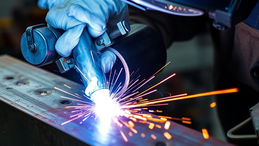
A plug weld joins overlapping metal parts through a round hole in the upper piece. The welder melts the exposed lower piece first, then fills the hole and ties the weld into its edge. The method is common in sheet-metal fabrication and some vehicle repairs, but hole size, spacing, and weld count must come from the drawing, welding procedure, or vehicle maker.
Good results depend on clean metal, tight contact between the layers, correct heat, and a test weld made from the same material and thickness. A full-looking weld face is not enough by itself; the weld must fuse to the lower piece and around the hole.
Quick Answer
A plug weld is a round weld made through a hole in one overlapping metal part to fuse it to the part below. Drill or punch the specified hole, clean and clamp the joint, establish the weld puddle on the lower sheet, fill the hole, and verify fusion on a matching test coupon.
Key Takeaways
- A plug weld is made through a round hole in an overlapping member; a slot weld uses an elongated opening.
- There is no universal hole diameter or spacing for every job. Follow the drawing, welding procedure specification, engineer, or vehicle-maker repair procedure.
- Clean both sides of the joint and clamp the layers in firm contact so the arc can fuse the lower piece.
- Set the welder on matching scrap and perform a destructive test before welding a vehicle or other critical part.
- Control fumes, fire, heat, and nearby wiring or fuel-system hazards before striking an arc.
At a Glance
| Time Required | About 20–45 minutes for setup, practice, and several welds; more for complex repairs |
| Difficulty | Intermediate; critical repairs require an approved procedure and proven welding skill |
| Tools Needed | MIG/GMAW or TIG/GTAW welder, drill or hole punch, deburring tool, clamps, cleaning tools, PPE, and fume control |
| Cost | Low consumable cost if you already own the welder; equipment and repair-information costs vary |
What’s in This Article
- What Is a Plug Weld?
- Plug Weld vs. Slot Weld and Rosette Weld
- When Should You Use Plug Welding?
- Before You Start: Design and Safety
- Tools and Materials You Need
- How to Choose Hole Size and Spacing
- How to Drill Plug-Weld Holes
- How to Clamp the Metal
- How to Set the Welder and Test
- How to Weld Through the Hole
- How to Control Heat and Distortion
- How to Check Fusion
- MIG Spot Welding vs. Plug Welding
- Plug-Weld Symbols on Drawings
- Common Mistakes and Troubleshooting
- Frequently Asked Questions
- Conclusion
- Sources
What Is a Plug Weld?
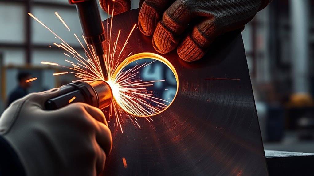
A plug weld joins overlapping members through a round hole in one member. Weld metal fills the opening and fuses with the exposed surface below and the wall of the hole. This definition matches the standardized use of plug welds described in Miller’s welding-symbol guide.
Plug welds are most common in lap-style joints, panel flanges, brackets, and other assemblies where a long seam is not needed or cannot be reached. They can carry useful load, but the joint is only structural when its size, number, spacing, material, filler metal, and acceptance criteria come from an approved design or procedure.
A plug weld is not sized by the same rules as a fillet weld. Use the drawing or welding procedure for the plug-weld requirements; use fillet weld sizing only when the joint actually calls for a fillet weld.
A smooth, full weld face does not prove that the lower sheet fused. Confirm the process on a matching test coupon before welding a critical part.
Plug Weld vs. Slot Weld and Rosette Weld
A plug weld uses a round hole. A slot weld uses an elongated hole. Both join overlapping members, but the drawing may specify different dimensions, pitch, fill depth, and orientation.
Rosette weld is a shop term often used for a round plug weld. On drawings, use the standardized term and symbol required by the applicable code or company practice so the fabricator and inspector read the same requirement.
| Weld type | Opening | Typical reason to use it |
|---|---|---|
| Plug weld | Round hole | Localized attachment through an overlapping member |
| Slot weld | Elongated slot | Longer load-transfer area or a drawing-specific joint |
| Rosette weld | Usually round | Informal name commonly used for a plug weld |
When Should You Use Plug Welding?
Use plug welding when two parts overlap and the design calls for a weld through one member into the other. Common examples include sheet-metal flanges, brackets, furniture frames, panel replacement, and assemblies where the back side cannot accept a normal fillet bead.
Plug welding can provide a compact joint and a surface that can be dressed flush when the procedure allows it. It also places welds at defined points, which helps control appearance and heat better than an unnecessary continuous seam.
Do not choose plug welding simply because access is tight. First confirm that the base metal is weldable, the hole can maintain the required edge distance, the lower piece is thick enough to accept the heat, and the joint design permits a plug weld.
Note: On vehicle repairs, plug welds may replace factory spot welds only where the repair procedure allows that attachment method. Verify the exact year, make, model, VIN, part, hole size, weld count, and location before cutting or welding.
Before You Start: Joint Design and Safety
For structural fabrication, use the engineer’s drawing and the applicable welding procedure specification. For vehicle repair, follow the body repair manual and current vehicle-maker procedures. I-CAR states that vehicle-maker procedures are service specifications and should be checked for the exact year, make, model, and part.
Inspect both sides of the work area before drilling. Look for fuel and brake lines, wiring, airbag components, batteries, seam sealer, foam, undercoating, glass, and other materials that heat or sparks could damage.
Warning: Welding produces hot metal, ultraviolet radiation, sparks, fumes, and electrical hazards. Remove combustible coatings as required, use local exhaust or adequate ventilation, keep a suitable fire extinguisher nearby, and protect hidden cavities. For galvanized steel, follow safe coating-removal and fume-control practices; see this guide to MIG welding galvanized steel and OSHA’s welding ventilation requirements.
On vehicles, disconnect and isolate electrical systems exactly as the repair information requires. High-voltage vehicles need model-specific disable, verification, and waiting procedures. Place the work lead on clean metal close to the weld so current does not travel through bearings, modules, or other sensitive paths.
Do not weld pressure vessels, lifting devices, safety cages, frames, suspension parts, or other life-safety components without a qualified design, approved procedure, and the required welder qualification.
Tools and Materials You Need for Plug Welding
Gather the equipment before you strike an arc. The exact setup depends on the metal, thickness, code, and repair procedure.
- GMAW/MIG or GTAW/TIG welder matched to the material and procedure
- Correct electrode wire or filler rod, shielding gas, polarity, and torch consumables
- Drill, drill press, hole punch, or approved hole-making tool
- Center punch, ruler, square, template, or hole-duplicating tool
- Deburring tool, file, wire brush, abrasive disc, or spot-cleaning tool
- Plug-weld clamps, locking pliers, C-clamps, or a fixture that holds the layers flat
- Work lead with a clean contact point close to the joint
- Welding helmet, safety glasses, gloves, hearing protection, flame-resistant clothing, and closed footwear
- Local fume extraction, welding screens, and a suitable fire extinguisher
- Matching scrap metal for setup and destructive testing
Clean metal and correct fit-up matter more than extra filler. The basic joint-preparation steps are to remove contamination, verify fit, secure the work, and test settings before the final weld.
Products Worth Considering

HEAVY DUTY ELECTRODE HOLDER — Built for high-amperage stick welding with a copper alloy jaw that grips electrodes tight. This heavy duty stinger handles thick plate down to thin sheet metal with consistent grip. The insulated handle forms a heat barrier for longer welding sessions
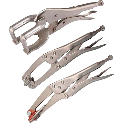
Includes 10in. plug weld plier, 10in. locking plier and 10in. claw welding clamp.

16-Pack Welding Clamps Set: Includes 16 butt welding clamps designed for precise edge-to-edge welding, ideal for body repair, floor patching, door skins, and sheet metal alignment.
Essential Plug-Welding Tools
A drill press produces repeatable holes on removable parts. A hand drill or punch can work on installed panels when access is limited. Use a center punch so the bit does not walk, then deburr both faces without thinning the sheet.
Use clamps that leave the hole open and hold the faying surfaces together. A magnet may help with temporary positioning, but it should not replace firm mechanical clamping, and strong magnetic fields can disturb some DC arcs.
Materials and Safety Gear
Match the filler metal and shielding gas to the base metal and the approved procedure. For light-gauge steel, a small solid wire often gives better heat control than a large wire. Miller recommends .023- or .024-inch wire for much light sheet work, while the machine chart and test coupon should determine the final settings.
Use dedicated stainless-steel or aluminum cleaning tools when cross-contamination is a concern. If you weld aluminum, remove oxide and contamination from the joint area; this guide to cleaning aluminum before welding explains why surface preparation matters, although conventional gas-shielded processes are normally preferred for sound aluminum welds.
How to Choose Plug-Weld Hole Size and Spacing
Do not use one hole diameter or one spacing rule for every job. Hole size affects access to the lower piece, heat input, fused area, edge distance, and the amount of filler needed. Spacing and weld count affect load transfer and distortion.
| Application | What controls the hole and spacing | Practical rule |
|---|---|---|
| Structural or engineered fabrication | Drawing, code, engineer, and WPS | Do not substitute a shop rule for the specified dimensions |
| Automotive steel collision repair | VIN/model-year body repair procedure and OEM general welding information | I-CAR gives 8 mm (5/16 inch) only as a general fallback when no OEM size is available and the flange supports it |
| Noncritical shop project | Material thickness, flange width, edge distance, test results, and load | Prove the setup on matching scrap and avoid crowding the edge |
For automotive repairs, review I-CAR’s steel spot- and plug-weld nugget guidance, then follow the vehicle maker whenever its procedure gives a different requirement. Match the factory weld count and locations when the procedure says to do so.
Note: The often-repeated 25–40 mm spacing and 7.5 mm hole rules are not universal. They may fit a specific repair or project, but they should not replace the drawing, WPS, or OEM procedure.
How to Drill Plug-Weld Holes
Mark each location with a template, measuring tool, or the original panel as required. Center-punch the mark, support the work, and drill or punch only the upper member unless the procedure calls for another preparation.
- Confirm the layout. Check hole diameter, count, spacing, edge distance, and which member receives the holes.
- Secure the part. Clamp loose work so it cannot spin or catch the bit.
- Make the hole. Use a sharp tool and steady pressure. Do not force a dull bit through thin sheet.
- Deburr both faces. Remove sharp edges and raised metal without enlarging the hole beyond the allowed size.
- Clean the weld zone. Expose bright, weldable metal on the hole wall and on the lower member beneath the opening.
| Step | Action | Result |
|---|---|---|
| 1 | Punch the marks | The bit starts on location |
| 2 | Drill or punch the upper member | The lower member remains intact |
| 3 | Deburr and clean | The layers can clamp flat and the arc reaches clean metal |
If a coating must remain between flanges for corrosion protection, use only the product and preparation method allowed by the applicable procedure. Do not assume every “weld-through” coating is approved for every joint.
How to Clamp Metal for Plug Welding
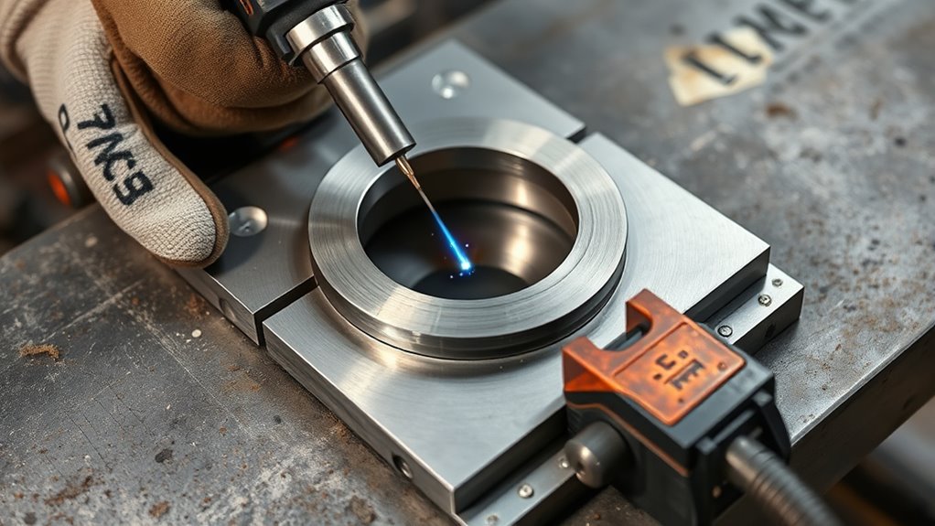
Align the parts, then clamp the upper member tightly against the lower member. The hole must remain open, and the torch should approach it close to square. A gap can let the top sheet melt back before the lower piece forms a stable puddle.
Clamp Alignment
Use reference marks, cleco-style temporary fasteners where permitted, magnets for initial positioning, or a fixture to hold the parts in location. Finish with mechanical clamps that keep the layers flat.
| Step | Tool | Check |
|---|---|---|
| 1 | Reference marks or fixture | Part location and overlap |
| 2 | Plug-weld clamp or locking pliers | Sheets are in full contact |
| 3 | Gauge or template | Hole size, pitch, and edge distance |
Torch Access Space
Place the clamp close enough to hold the interface tight but far enough away to leave the nozzle or TIG cup clear. Keep the gun cable and work lead arranged so they do not pull the torch off center.
Secure Flange Contact
Tighten the clamp until the metal cannot move, but stop before the flange buckles. Recheck the gap beside every hole. When cleaning or finishing the area, use a controlled grinding angle so you do not thin the panel.
How to Set the Welder and Test the Joint
Use the welding-machine chart, wire or filler manufacturer guidance, and the approved procedure as the starting point. Plug-weld settings are not universal because total thickness, coating, hole size, position, shielding gas, wire diameter, joint gap, and machine output all change the result.
For light steel sheet, short-circuit GMAW with small solid wire is common because it offers good puddle control. TIG can also make plug welds, but it is slower and requires careful control of arc length, filler addition, and heat.
- Prepare two coupons from the same metal type, coating condition, thickness, and layer count as the final joint.
- Make the same hole and clamp the coupons with the same overlap and gap.
- Set polarity, shielding gas, voltage or amperage, wire speed, and torch consumables correctly.
- Make a practice weld and inspect the face for complete fill, tie-in, undercut, porosity, and burn-through.
- Tear, twist, peel, or otherwise destructively test the coupon using the accepted method for the application.
- Adjust the machine or technique until the fused area and failure mode meet the procedure’s acceptance criteria.
Pro Tip: Record the machine, wire, gas, settings, hole size, material stack, and test result. If any of those variables change, make another test coupon before continuing.
If the machine feeds poorly, loses gas coverage, or produces an unstable arc, stop and correct the problem before welding the part. This MIG welder troubleshooting guide covers common feed, power, and shielding-gas checks.
How to Weld Through the Hole
Hold the GMAW gun or TIG torch close to square with the opening. Aim at the lower member through the hole. The first goal is to establish fusion on the lower piece; the second is to connect that puddle to the edge of the upper member and fill the opening.
- Position the torch. Keep the electrode centered or use the start point required by your procedure.
- Establish the puddle on the lower piece. Pause only long enough to see the lower metal melt.
- Tie into the hole wall. Move outward in a small circle, or start at the edge and circle as your tested technique requires.
- Fill the opening. Avoid skips, voids, excessive crown, and undercut around the edge.
- Release and hold position briefly. Keep shielding gas over the cooling puddle as the equipment requires.
Do not weave widely or dwell longer than needed. Excess heat can burn through the lower sheet, enlarge the hole, damage coatings, or warp the assembly. For thin material, review these heat-control principles for thin metal; gas-shielded solid wire is often easier to control than self-shielded flux-core on light sheet.
Flux-core methods can work in suitable fabrication, but they add slag and often more heat. If you use them, follow the wire manufacturer’s directions and these flux-core setup checks, then prove the joint on scrap.
How to Control Heat and Distortion
Weld shrinkage can pull panels out of shape. Spread the heat instead of completing a long row from one end to the other. Make one weld, move to a distant location, and return after the area cools enough for the procedure.
- Use the fewest welds allowed by the design; extra welds add heat and may not add strength.
- Keep the joint clamped until the welds have cooled enough to hold alignment.
- Use a skip sequence on long flanges.
- Do not quench a critical weld unless the procedure allows it.
- Use a copper chill bar only where access and the procedure permit; keep it clean and firmly supported.
Miller’s sheet-metal welding guidance recommends tight fit-up and distributing heat to reduce burn-through and warping.
How to Check Plug-Weld Penetration and Fusion
Start with visual inspection. The hole should be completely filled to the required depth, with consistent tie-in at the edge, no visible cracks, no undercut beyond the acceptance limit, no open porosity, no missed areas, and no excessive crown.
Backside discoloration or a heat mark may show that heat reached the lower member, but it does not prove the fused area or strength. I-CAR advises making a weld on matching scrap, visually inspecting it, and then destructively testing it before welding the vehicle.
| Inspection | What it can show | What it cannot prove alone |
|---|---|---|
| Weld-face appearance | Fill, profile, tie-in, cracks, porosity, spatter | Actual fused diameter at the interface |
| Backside heat mark | Heat reached the lower member | Adequate fusion or joint strength |
| Destructive coupon test | Fused area and failure behavior for that setup | Future quality if settings, material, fit-up, or technique change |
Use the destructive-test method and acceptance criteria required by the code, employer, engineer, or vehicle maker. I-CAR’s destructive weld-testing overview explains why matching coupons are needed before a critical repair.
Grinding and Corrosion Protection
Dress the weld only when the drawing or repair procedure allows a flush surface. Use light pressure and stop before the surrounding base metal thins. I-CAR testing found little tensile-strength difference between properly made dressed and undressed steel plug-weld coupons, but that result does not excuse grinding into the fused joint or surrounding sheet.
After inspection, restore corrosion protection, seam sealer, cavity wax, primer, paint, and other coatings exactly as the project or vehicle procedure requires. Do not trap slag, porosity, sharp edges, or hot metal under a coating.
MIG Spot Welding vs. Plug Welding
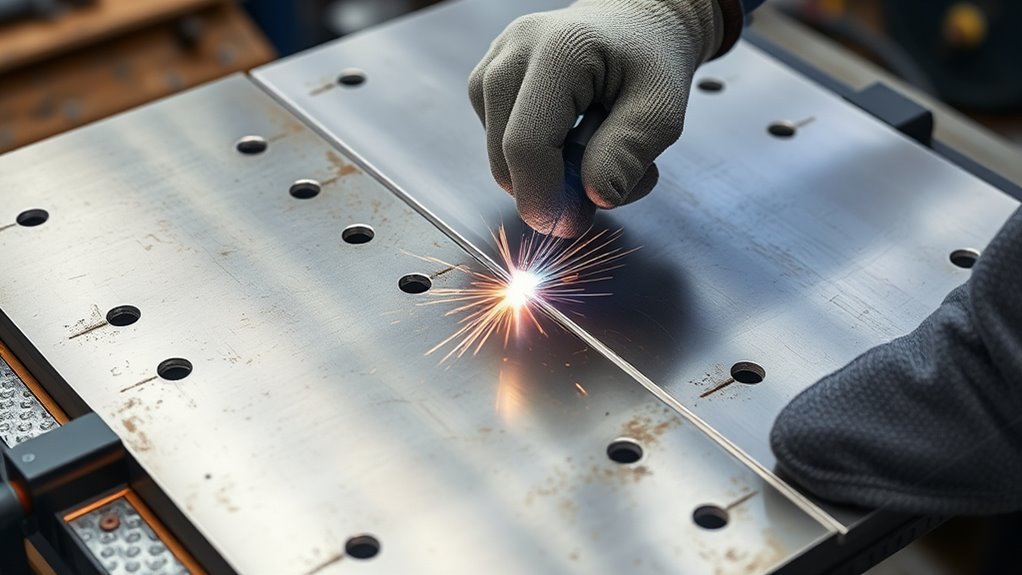
The phrase MIG spot welding is often used loosely. It may mean a timed GMAW plug weld through a prepared hole, a GMAW arc spot weld made through an unpierced upper sheet, or it may be confused with resistance spot welding. These are different attachment methods.
| Method | Hole in upper sheet? | Access | Main limitation |
|---|---|---|---|
| GMAW plug weld | Yes | One-side torch access | Requires hole preparation, cleaning, and testing |
| GMAW arc spot weld | Not always | One-side torch access | Highly dependent on approved procedure, thickness, and heat control |
| Squeeze-type resistance spot weld | No | Electrodes normally need both sides | Needs specialized equipment and suitable access |
For vehicle repair, do not choose the method only by speed or convenience. Use the attachment method, equipment, settings, weld count, and locations allowed by the OEM procedure. Clean metal is required; do not weld over dirty or painted surfaces.
Plug-Weld Symbols on Drawings
The current U.S. reference is AWS A2.4:2020. Read the complete welding symbol, notes, detail views, and referenced specifications before making holes.
Under AWS practice, the basic plug-weld symbol is rectangular. The plug diameter is placed to the left, pitch is placed to the right, and the number of plugs may appear in parentheses. The arrow-side or other-side placement identifies which member contains the holes. If the hole is not filled completely, the required fill depth is shown inside the symbol.
| Symbol cue | Meaning | Action |
|---|---|---|
| Plug-weld rectangle | A plug weld is required | Check which member receives the hole |
| Ø dimension to the left | Plug diameter | Prepare the specified diameter |
| Number in parentheses | Quantity of plug welds | Make the count shown |
| Pitch to the right | Center-to-center spacing | Lay out the spacing shown |
| Depth inside the symbol | Partial-fill requirement | Do not overfill or underfill the specified depth |
| Countersink angle and depth | Hole preparation detail | Machine the taper exactly as shown |
AWS A2.4:2020 changed the graphic convention: the diameter mark is no longer built into the basic plug-weld symbol, although the Ø mark is still used with the plug-size dimension. Understanding welding process selection does not replace reading the symbol and referenced procedure.
Common Plug-Welding Mistakes and Troubleshooting
Most failures begin with a wrong hole, contamination, a gap, an untested setting, or poor torch placement. Correct the setup before adding more heat.
- Using a universal hole size: Follow the drawing, WPS, or OEM procedure instead of copying a number from another job.
- Off-center arc: Aim through the hole at the lower member and keep the torch stable.
- Dirty faying surfaces: Remove paint, rust, oil, scale, moisture, and unapproved coatings from the fusion area.
- Poor clamping: Eliminate gaps so the upper sheet does not melt away before the lower sheet fuses.
- No destructive test: A good-looking face can hide a small fused area.
- Too many welds: Extra plugs add heat, distortion, and cleanup without automatically improving the joint.
- Overgrinding: Dress the crown, not the surrounding sheet or fused interface.
- Skipping corrosion protection: Restore approved coatings after the weld passes inspection.
| Symptom | Likely causes | Correction |
|---|---|---|
| Weld peels from lower sheet | Low heat, arc stayed on upper edge, contamination, or a gap | Clean and reclamp; aim at the lower piece; retest settings |
| Burn-through | Excess heat or dwell, poor fit-up, wrong hole, or thin lower metal | Shorten dwell, correct the gap, lower heat as testing permits, and verify hole size |
| Porosity | Oil, paint, rust, moisture, gas leak, low flow, or drafts | Clean the joint and check gas flow, hoses, nozzle, and wind protection |
| Hole not fully filled | Poor motion, short weld time, wire-feed problem, or oversized hole | Correct feed and technique; use the specified hole; retest |
| Panel warps | Crowded welds, long dwell, poor sequence, or weak clamping | Use the required count, skip around, allow cooling, and improve fixturing |
Products Worth Considering
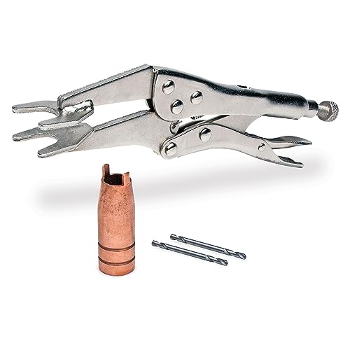
Duplicate full-penetration OE spot welds from one side with your existing MIG welder

Complete Kit: Ideal for HVAC & Light Duty Brazing - Designed specifically for light-duty brazing and welding jobs, this kit is your go-to tool for HVAC repairs, metal crafts, and other precision tasks. Its portable design is perfect for on-the-go professionals

High-quality solid brass Dinse Style TIG Welding Cable Plug Connector with INLINE Gas. Compatible with 1-Piece TIG Welding Cables.
Frequently Asked Questions
Can plug welds be ground flush afterward?
Yes, when the drawing or repair procedure permits it. Remove only the crown needed for the required contour, keep the grinder off the surrounding base metal, and inspect the finished joint. Do not grind into the hole edge or fused interface.
Are plug welds as strong as seam welds?
Not as a universal rule. A seam weld provides continuous attachment, while plug welds transfer load at separate points. Either can be correct when the joint is designed, sized, welded, and inspected for its load path. Do not substitute one for the other without approval.
What metals are best for plug welding?
Mild steel is common and forgiving. Stainless steel and aluminum can also be plug welded with the correct process, filler, cleaning, shielding, heat control, and approved procedure. Coated, hardened, or dissimilar metals need material-specific guidance.
How many plug welds are usually needed?
Use the number and spacing on the drawing, WPS, engineering detail, or vehicle repair procedure. There is no safe universal count. Too few may not carry the load, while unnecessary welds can add heat and distortion.
Can plug welding be used on painted metal?
Do not weld through ordinary paint, rust, oil, or undercoating. Clean the fusion area on both layers. Use weld-through primer or another coating between flanges only when the applicable procedure and coating manufacturer allow it.
What does a good plug weld look like?
The hole is filled to the required depth, the edge is tied in evenly, and the face has no visible crack, open porosity, missed area, severe undercut, or excessive crown. Final acceptance also requires a proven test coupon or inspection method, not appearance alone.
What size hole should I drill for a plug weld?
Use the specified diameter on the drawing or repair procedure. For automotive steel repair only, I-CAR lists 8 mm (5/16 inch) as a general fallback when no OEM size is available and the flange is wide enough. That is not a universal fabrication rule.
What is the difference between a plug weld and a slot weld?
A plug weld fills a round hole in an overlapping member. A slot weld fills an elongated opening. Their symbols and dimensions differ, so follow the drawing for diameter or width, length, pitch, quantity, and fill depth.
Safety Disclaimer: This article is for general information and does not replace hands-on training, a qualified welding procedure, engineering approval, shop rules, or vehicle-maker repair information. Use the required PPE, ventilation, fire controls, electrical isolation, and inspection method before welding.
Conclusion
A plug weld is a compact way to join overlapping metal through a round opening, but the hole itself does not make the joint strong. Strength comes from the correct design, clean metal, tight fit-up, proven settings, full fusion, and proper inspection.
Start with the drawing, WPS, or VIN-specific repair procedure. Prepare and clamp the joint, test the exact setup on matching scrap, weld into the lower member and around the hole edge, then inspect and restore corrosion protection.
When a critical procedure is missing or unclear, stop and obtain qualified guidance instead of guessing at hole size, spacing, heat, or weld count.
Sources
- OSHA 29 CFR 1910.252 — Welding, Cutting, and Brazing — ventilation, fumes, zinc-coated metal, and general welding-safety requirements
- I-CAR — Steel Spot and Plug Weld Nugget Size — OEM-first hole-size guidance, general automotive fallback dimensions, and test requirements
- I-CAR — Destructive Weld Testing — matching test coupons, visual inspection, and destructive verification
- Miller Electric — Successfully Welding Sheet Metal With MIG and TIG — wire size, fit-up, heat control, backing bars, and distortion reduction
- Miller Electric — How to Read and Understand Weld Symbols — plug- and slot-weld definitions and symbol dimensions
- American Welding Society — AWS A2.4:2020 — current U.S. standard for welding-symbol construction and interpretation




