
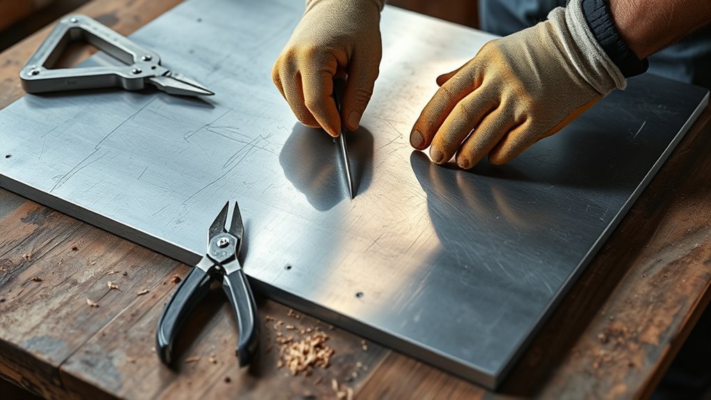
One wrong line can turn a good sheet of metal into scrap. Accurate cuts start before the saw, snips, wheel, or plasma torch touches the work. You need a clean sheet, one reliable reference edge, the right measuring tools, and thin marks that show exactly which side becomes the finished part.
Quick Answer
Clean and support the sheet, choose one straight datum edge, and measure every feature from that same reference. Use a steel rule or tape for size, a square for 90-degree lines, and calipers or a micrometer for thickness. Mark a thin line, identify the waste side, and allow for the cutting tool’s kerf.
Key Takeaways
- Clean, deburr, and support the sheet before taking measurements.
- Measure from one datum edge instead of chaining dimensions from mark to mark.
- Use a scribe for durable precision marks or a fine marker when you must protect the surface finish.
- Check width, length, parallel lines, corners, and diagonals before cutting a large rectangular panel.
- Mark the waste side and confirm the real kerf with the tool manual, cut chart, or a scrap test.
At a Glance
| Time Required | 10 to 20 minutes for a simple cut; longer for large panels, curves, or tight-tolerance parts |
| Difficulty | Beginner to intermediate |
| Tools Needed | Steel rule or tape, square, straightedge, calipers or micrometer, scribe or fine marker, clamps, and cleaning supplies |
| Cost | No extra cost if you already own basic layout tools; otherwise, cost varies by tool quality |
Before You Begin: Safety and Setup
Set aside about 10 to 20 minutes for measuring and marking a simple cut. Large panels, repeated parts, curves, or close-fitting pieces take longer because they need more reference checks.
Keep these tools and supplies close before you start:
- Retractable steel tape measure for larger sheets
- Steel rule or rigid straightedge for short, precise measurements
- Engineer’s square, combination square, carpenter’s square, or framing square
- Digital or dial calipers; use a micrometer when thickness tolerance is especially tight
- Carbide scribe, fine permanent marker, or layout dye and scribe
- Dividers, trammel points, or a template for circles and curves
- Clamps or another secure support method
- Clean cloth, nonwoven abrasive pad, deburring tool, or metal brush
Warning: Sheet edges and fresh cuts can cause severe lacerations. Wear suitable hand protection while carrying and positioning sheet metal, but keep gloves away from exposed rotating or moving machinery where they could snag. Use eye protection for cutting hazards, secure the work, keep guards installed, and follow the cutting-tool manufacturer’s instructions.
Before laying out the part, read the drawing or project plan and identify the required finished dimensions and tolerance. Decide whether the dimensions refer to the finished edge, a bend line, a hole center, or a cutout. Mixing those references is a common source of errors.
Choose the Right Measuring Tools for Sheet Metal
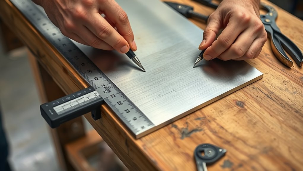
Match the tool to the measurement. A retractable steel tape is useful for the overall length and width of a large sheet. Lock the tape only after the hook is seated correctly, and keep the blade straight instead of letting it bow across the surface.
Use a steel rule for shorter measurements because its rigid edge gives you a more stable reference. Use a square to create or check a 90-degree line. For long cuts, place marks near both ends and connect them with a straightedge instead of trusting one distant mark.
Use digital or dial calipers to check sheet thickness, outside dimensions, small offsets, and feature sizes. Calipers work on steel, stainless steel, aluminium, brass, copper, and other sheet materials. Clean the jaws, close them gently to confirm zero, keep them square to the sheet, and use light pressure. Mitutoyo’s caliper guidance stresses correct alignment and light measuring force.
A micrometer is often the better choice when you need a more precise thickness reading. Measure away from burrs, heavy coatings, damaged corners, and rolled edges, then compare readings at several locations if thickness variation could affect fit.
For marking, a sharp scribe makes a thin, durable line. A fine permanent marker is easier to see and does not scratch a finished face. Layout dye improves contrast when a bare metal surface makes a scribe line hard to see. A marking knife is not the first choice for metal because it can dull quickly and may create a wider or less controlled scratch than a proper scribe.
Keep power tools out of the measuring area until the layout is complete. Vibration, cords, sparks, and debris can shift the sheet or hide your marks. Also prepare the metal before later welding or joining work.
Products Worth Considering
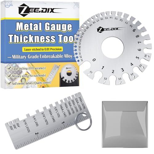
Packing:1 round double-sided metal wire gauge + 1 metal plate thickness gauge.This product can help you check the wire diameter of sheet metal before welding or working.You can get accurate data before welding to avoid unnecessary errors

【1x Round Double-sided Stainless Steel Gauge】The 0-36 Standard stainless steel metal sheet size tool, eliminates the need for two types of metal gauges.

HIGH-QUALITY MATERIAL: Made of stainless steel, it has anti-rust and anti-corrosion properties. It is durable, it will not rust in dry environment, and it is easy to store. You can use it for a long time without changing it frequently,compact and light in weight, easy to carry. Leather packaging provides better protection and portability.
Clean and Flatten the Sheet Metal Surface
Clean the sheet before measuring so grease, loose scale, chips, and oxidation do not hide marks or hold a tool away from the surface. Remove burrs from the reference edge with a deburring tool or fine abrasive, then wipe the area dry.
Support the sheet on a flat, stable surface that will not flex. Use a straightedge to check for bows, high spots, dents, and damaged edges. A spirit level tells you whether a surface is level, but it does not prove that the sheet itself is flat.
If the sheet has protective film and the finished face must remain unmarked, leave the film in place when the cutting method allows it and use a fine marker on the film. Do not drag a scribe across a cosmetic face unless the scratch will be removed by the cut or later finishing.
Remember that proper preparation supports accurate fabrication and better fit-up.
| Check | What to Look For | Corrective Action |
|---|---|---|
| Surface | Oil, dirt, loose scale, chips, or oxidation | Clean and dry the layout area |
| Reference edge | Burrs, dents, waves, or an out-of-square corner | Deburr it or create a new straight datum edge |
| Shape | Bows, dents, or unsupported areas | Support and flatten the sheet before layout |
| Finish | A cosmetic or coated face that must not be scratched | Use film, removable tape, or a fine marker |
Set a Datum Edge and Plan the Layout
A datum is the reference edge or point from which you take measurements. Choose the straightest usable factory edge, a verified trimmed edge, or a clearly established centerline. Mark it lightly so you do not switch references halfway through the job.
Measure every related feature from that same datum whenever the drawing allows it. Avoid chain measuring, where each new mark starts from the previous mark. Small errors can add together and move the final feature out of position.
- Confirm the finished size. Separate overall dimensions from hole locations, notches, bend lines, and seam allowances.
- Choose the finished face. Decide which side must stay clean and which side may carry scribe marks.
- Choose the datum edge. Check it with a straightedge and square before trusting it.
- Plan the cut order. Leave enough material for clamps and support, especially around narrow strips or small parts.
- Mark the waste area. Add a clear X or the word “waste” so you do not cut on the wrong side.
Note: If the part will be bent later, the flat size may need bend allowance or bend deduction. Do not measure a formed part’s outside dimensions directly onto flat stock unless the drawing already includes the correct flat pattern.
Measure Sheet Metal for a Precise Cut
-
Verify the stock. Measure the sheet’s overall length and width, then confirm its thickness and material. Do not rely only on a handwritten gauge label.
-
Check the datum. Make sure the chosen edge is straight and the starting corner is square enough for the layout. Trim or re-establish the reference if needed.
-
Make paired tick marks. For a long straight cut, mark the required distance near both ends of the sheet. This makes a parallel line easier to verify.
-
Connect the marks. Hold a rigid straightedge through both ticks, then draw or scribe one thin line. Do not use the edge of a flexible tape as the line guide.
-
Check the full part. Measure length and width again. For a rectangular layout, compare the two diagonals after confirming opposite sides are equal. Equal diagonals are a useful check that the rectangle is square.
-
Record critical dimensions. Write them on the plan or a clean margin of the sheet so repeated parts use the same values.
Measure from the same side of the tape or rule each time, and keep your eye directly above the graduation to reduce parallax error. These habits reduce scrap and improve fit when panels are later joined with flux core welding techniques.
The cut can only be as accurate as the datum, the measuring method, and the line you give the tool to follow.
Mark Straight Lines, Curves, and Hole Centers
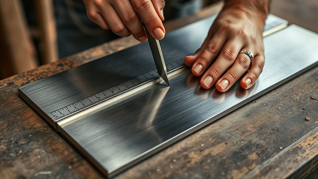
Use a scribe when you need the thinnest, most durable line and a small surface scratch is acceptable. Hold the scribe at a consistent angle and make one light, controlled pass along a clamped or firmly held guide. Repeated heavy passes can widen the line and create a stress raiser in thin or highly stressed material.
Use a fine permanent marker when the sheet is coated, polished, painted, or covered by protective film. If the marker line is wider than your tolerance, place the cut consistently at one edge of the line rather than trying to split it by eye.
For circles and arcs, set dividers or trammel points from a marked center. For irregular curves, use a rigid template and trace it without changing the template’s position. When several holes share the same centerline, establish the centerline first, then measure each center from the datum.
Use a center punch only where a drill or punch operation needs a starting point. Support thin sheet from below and use a light strike so you do not stretch or dish the panel. A center-punched dot is not a substitute for a clearly marked cut profile.
Warning: A scribe is sharp. Cap or store it when not in use, keep your free hand out of its path, and never hold the sheet where the cutting tool will pass.
After marking, inspect the full line under good lighting. Check that it is continuous, easy to follow, and on the correct face. Use only grinder-rated accessories if an angle grinder will make the cut.
Use a Square to Keep Cuts Straight
Set an engineer’s square, combination square, carpenter’s square, or framing square against the verified datum edge to mark a 90-degree line. Hold the stock firmly against the edge so the tool cannot rock while you draw the line.
Check the square before using it for critical work. Draw a line from a straight reference edge, flip the square over against the same edge, and draw a second line from the same starting point. A gap between the two lines shows that the square or the reference edge needs attention.
For wide panels, mark the required distance at both ends and use a long straightedge to connect the points. Then use the square to confirm the line’s relationship to the datum. This avoids the drift that can occur when a short square is extended in several steps.
Before cutting, clamp a guide when the tool and manufacturer allow it. Apply gentle, steady pressure instead of forcing the cutting tool away from the layout line.
Products Worth Considering

Black precision-etched scales

Multi-function: The combination square is widely used in woodworking, furniture making, and construction. It allows for precise length measurements, 45° and 90° angle marking, quick line drawing, depth and height measurements, and horizontal/vertical alignment. The built-in level bubble helps craftsmen accurately align components, preventing misalignment

COMBO SQUARE: This Johnson combination square was designed with maximum accuracy in mind - its square head is CNC machined for greater accuracy.
Allow for Kerf Width Before You Cut
Kerf is the width of material removed by a saw, cutoff wheel, plasma arc, laser, or other cutting process. It is not one fixed number. It changes with the blade or wheel width, nozzle and consumable condition, amperage, speed, material, thickness, and cutting method.
Hypertherm explains that plasma systems use kerf compensation to keep the kerf on the waste side and hold the finished part to size. Its cut-quality guidance also notes that nozzle size and other variables affect kerf width.
| Cutting Method | Layout Approach |
|---|---|
| Tin snips or hand shears | Keep the curling or distorted waste on the offcut side and follow the tool’s blade path consistently. |
| Saw or cutoff wheel | Keep the full blade or wheel width on the waste side when the finished dimension matters. |
| Plasma, laser, or waterjet | Use the equipment’s cut chart or programmed kerf compensation, then verify with a test coupon when tolerance is tight. |
| Bench shear or guillotine | Align the finished dimension to the machine’s actual cut reference and account for blade clearance and any distortion. |
Pro Tip: Make a test cut in scrap from the same material and thickness. Measure the result, then adjust the guide or tool path before cutting the finished part.
Double-Check Dimensions Before Cutting
Complete a final inspection before switching on any cutting tool. Compare the layout with the project specifications, and use the same measuring method that created the marks.
- Datum: Are all related measurements taken from the correct reference edge or centerline?
- Stock: Did you confirm the material, thickness, and finished face?
- Overall size: Do the marked length and width match the plan?
- Squareness: Are the corners checked, and do the diagonals agree on a rectangular layout?
- Features: Are holes, slots, notches, and curves located from the correct datum?
- Waste side: Is the offcut clearly marked?
- Kerf: Will the blade, wheel, or programmed path stay on the waste side?
- Support: Is the sheet clamped or supported without covering the cut line?
- Safety: Are guards, eye protection, and the work area ready for the selected process?
If a dimension is critical, check it at more than one location. Warping, edge damage, coatings, and burrs can change a reading. Keep your measuring faces clean and do not squeeze thin sheet with excessive caliper force.
Clear marks and a stable setup help the cutting tool follow the intended path. Maintaining airflow in tools also supports performance and tool life when you use an angle grinder.
Avoid Common Sheet Metal Marking Mistakes
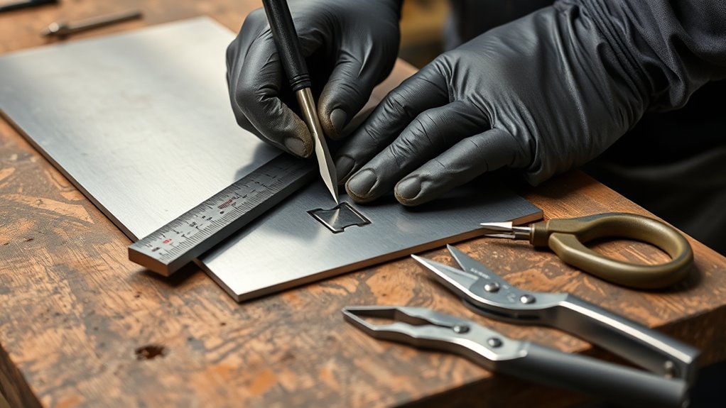
Most layout failures come from an unreliable reference, a mark that is too wide, or a cut made on the wrong side. Catch those problems before they turn into scrap.
| Mistake | What It Causes | Fix |
|---|---|---|
| Measuring from a burred or damaged edge | Every feature shifts by the edge error | Deburr the edge or establish a new datum |
| Chain measuring | Small errors build across the part | Measure related features from one datum |
| Using a thick marker line | The cutting reference becomes uncertain | Use a fine tip and follow one edge of the line |
| Scribing a cosmetic face | Permanent visible scratches | Mark protective film, tape, or the waste face |
| Ignoring kerf | The finished part becomes undersize | Keep the cut on the waste side or apply kerf compensation |
| Failing to label the waste side | The operator may cut the good side of the line | Add a large X before clamping the sheet |
| Extending a short square repeatedly | The line drifts across a wide panel | Mark two points and connect them with a long straightedge |
Always mark with a guide. A simple straight-edge guide jig can improve consistency when the cutting tool is designed to run against a guide.
Frequently Asked Questions
How do you mark sheet metal for cutting?
Clean and support the sheet, choose a straight datum edge, and measure from that edge. Use a square or straightedge with a scribe for a thin permanent line, or use a fine marker when the surface must not be scratched. Mark the waste side before cutting.
What is the 4T rule in sheet metal?
The 4T rule is a common design-for-manufacturing guideline that keeps holes, slots, and similar features about four material thicknesses away from a bend line or inside corner to reduce distortion. It is not a universal rule for every edge, material, bend radius, or process. Protolabs describes it as a quick bend-feature clearance guideline, so confirm the final requirement with the drawing, tooling, or fabricator.
How do you measure and mark sheet metal correctly?
Use one verified datum edge, keep the rule or tape straight, and make paired tick marks for long lines. Connect the ticks with a rigid guide, check the finished dimensions twice, label the waste side, and include the cutting process’s kerf or tool-path offset.
Which is thicker, 14 gauge or 16 gauge sheet metal?
For the same gauge system and material, 14 gauge is thicker than 16 gauge. Exact thickness differs between standard steel, galvanized steel, stainless steel, aluminium, and other materials, so use the material-specific chart or measure the sheet rather than relying on the gauge number alone.
Should you cut on the line or next to the line?
When the finished size matters, keep the cutting width on the waste side and leave the reference edge of the line on the finished part. The exact alignment depends on the tool, guide, blade width, and kerf compensation.
Is a scribe better than a permanent marker?
A scribe gives a thinner, more durable line, but it scratches the surface. A fine permanent marker is better for painted, coated, polished, or cosmetic sheet. Choose the method that matches the required tolerance and surface finish.
Should you use calipers or a micrometer for sheet thickness?
Calipers are fast and usually suitable for identifying stock and checking general thickness. A micrometer gives better control for tighter thickness tolerances. With either tool, clean the measuring faces, check zero, measure away from burrs, and use light, consistent pressure.
Conclusion
Accurate sheet metal cuts begin with a reliable datum, clean measuring faces, a stable sheet, and a thin line that clearly separates the finished part from the waste. Check the stock, measure every related feature from the same reference, verify squareness, and account for the real kerf of your cutting process. A few extra minutes at the layout stage can prevent an undersize part, poor fit-up, and wasted material.
Sources
- OSHA 29 CFR 1910.138, Hand Protection — supports protection against cuts, lacerations, abrasions, and punctures.
- OSHA 29 CFR 1910.133, Eye and Face Protection — supports eye protection where flying particles, molten metal, or harmful radiation are hazards.
- OSHA 29 CFR 1910.212, Machine Guarding — supports guarding against points of operation, rotating parts, flying chips, and sparks.
- Mitutoyo Caliper Measurement Guidance — supports correct alignment and light measuring force.
- Hypertherm Cut Quality and Kerf Guidance — supports kerf compensation and the effect of cutting variables on kerf width.
- Protolabs Sheet Metal 4T Guidance — supports the bend-feature clearance explanation and its design-for-manufacturing context.




