
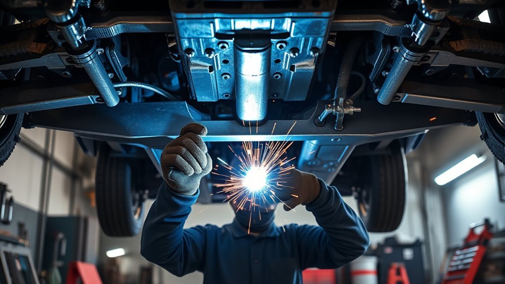
Welding a transmission crossmember is a structural drivetrain job, so the goal is not just to stick metal together. You need the vehicle level, the transmission supported, the mount centered, the driveline angles checked, and the weld area made safe before you strike an arc. Clean metal, careful measuring, short weld passes, and a final clearance check help prevent vibration, warping, cracked tabs, and mount failure.
Quick Answer
To weld a transmission crossmember, support the vehicle and transmission, clean the mounting area to bare metal, mock up the crossmember, mark the bolt holes, check clearance, and measure driveline angles. Tack both ends first, recheck fit, then weld in short controlled sections. Finish by inspecting the welds, painting bare metal, torquing the hardware, and checking for vibration.
Key Takeaways
- Do not weld until the vehicle is stable on jack stands, the transmission is supported, and all fuel, brake, wiring, and exhaust clearances are checked.
- Set the crossmember at ride height and measure the transmission output, driveshaft, and pinion angles with a digital angle finder.
- Use tack welds first, then recheck bolt-hole alignment, mount position, and clearance before final welding.
- Use short weld sections and cooling pauses so the crossmember and mounting tabs do not pull out of position.
- After welding, inspect for cracks, porosity, undercut, and interference, then torque the hardware to the vehicle or mount manufacturer’s specs.
At a Glance
| Time Required | 3 to 6 hours for mock-up, measuring, welding, cooling, inspection, and paint touch-up |
| Difficulty | Advanced DIY or professional welding job because it affects drivetrain support and alignment |
| Tools Needed | MIG welder sized for the metal thickness, welding PPE, jack stands, transmission jack or support stand, clamps, grinder, wire brush, drill, center punch, digital angle finder, straight edge, fire blanket, extinguisher, and torque wrench |
| Cost | About $50 to $300 for consumables and hardware if you already own the tools; more if fabrication or professional welding is needed |
Warning: A transmission crossmember is a load-bearing drivetrain support. If the frame is badly rusted, the crossmember is cracked through, the metal thickness is unknown, fuel vapor is present, or you are not confident welding structural steel, stop and use a qualified welder or fabrication shop. Follow OSHA hot-work precautions, keep an extinguisher nearby, and do not weld near unprotected fuel, brake, wiring, carpet, insulation, or undercoating.
Safety Checks Before You Weld
Before you prepare the crossmember, make the vehicle safe to work under. Park on a level surface, chock the wheels, and support the frame with rated jack stands. Do not rely on a hydraulic jack alone. Support the transmission with a transmission jack, screw stand, or padded jack so the mount does not drop or twist while you work.
Disconnect the negative battery cable and protect nearby electronics, wiring, rubber mounts, fuel lines, brake lines, and interior materials from heat and sparks. Remove loose combustibles from the work area, scrape away undercoating near the weld zone, and use a fire-resistant welding blanket where sparks could reach hoses or wiring.
Welding fumes can contain metal fumes and gases, so work in a well-ventilated area and use local exhaust or respiratory protection when needed. OSHA notes that welding hazards include metal fumes, UV radiation, burns, eye damage, electrical shock, and crush injuries, so wear a welding helmet, gloves, flame-resistant clothing, safety glasses, and hearing protection when grinding or drilling.
Gather Tools and Prep the Crossmember
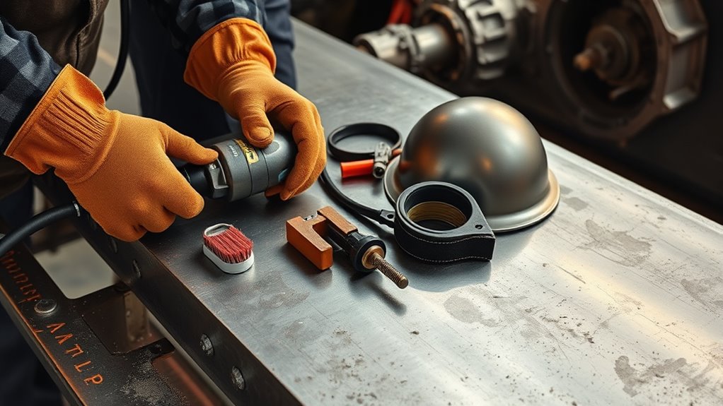
Before you start welding the transmission crossmember, gather a MIG welder that can handle the actual metal thickness, plus the correct wire, shielding gas, welding helmet, gloves, clamps, grinder, drill, angle finder, and measuring tools. A 220V machine gives more capacity on thicker brackets, but the real requirement is proper penetration for the material you are welding.
Clean the crossmember and mounting tabs until bare metal shows. Strip rust, paint, undercoating, oil, and grease from the weld area. Wipe the surfaces with a suitable solvent, let them dry fully, and keep chlorinated brake cleaner away from welding heat because heated solvent residue can create dangerous fumes.
Clean to bare metal, remove grease and rust, and let the joint dry before welding. Contamination can cause porosity, weak fusion, and uneven beads.
Check the crossmember against the transmission mount before drilling or welding. The mount should sit flat, the holes should line up without force, and the crossmember should clear the oil pan, converter bolts, exhaust, driveshaft, and floor. Clamp everything firmly so the parts cannot walk out of position when you tack weld.
Pro Tip: Mark the centerline of the frame, transmission output, mount pad, and crossmember before you tack anything. Matching centerlines make it easier to catch a small offset before it becomes a vibration problem.
Products Worth Considering

7 inch long with 1-3/4 inch jaw opening.

Amp & Jaw Capacity: Rated 400A with 2.01 inch jaw opening, providing a strong grip on thick plates and reliable grounding stability.

Measure the Transmission Crossmember Mounts
Start by leveling and securing the vehicle, then measure the crossmember location and mark the bolt-hole centers on the frame and mount. The transmission should be sitting at its intended installed height, with the engine and transmission supported in the same position they will hold after the job is finished.
Check the clearance between the transmission mount and frame, and verify the driveline angle so the transmission output shaft, driveshaft, and pinion are working together. Dana Spicer’s driveline operating angle guidance recommends measuring the driving member, driveshaft, and driven member to calculate U-joint operating angles.
Confirm the mount width spacing before you weld, and recheck every measurement. Small layout errors can create bolt-hole bind, rubber mount preload, exhaust contact, or driveline vibration.
Products Worth Considering

Durable high-impact molded body for maximum strength and lasting performance

VERSATILE DIGITAL ANGLE GAUGE AND LEVEL: Measure angles, check relative angles with zero calibration feature, or use as a digital level with ease

VERSATILE 3-IN-1 DIGITAL ANGLE FINDER: Measure inside and outside angles, lengths, and calculate miter saw cut angles with precision
Mark Bolt Hole Centers
Measure the distance between the transmission crossmember mounts first so you can position the bolt holes accurately on the frame side of the assembly. Use a caliper or measuring tape to find the center of each mount, then mark each bolt-hole center clearly with a scribe, paint marker, or center punch.
Keep each mark equidistant from the edges so the layout stays symmetrical and the load path remains balanced. Double-check your measurements against the crossmember, transmission mount, and vehicle service information before you drill. If anything is off, correct it now while the part is still loose.
Once the layout checks out, drill the marked locations with the proper bit size for the mounting bolts. Deburr the holes so the brackets sit flat and the bolts clamp evenly.
Check Clearance and Angle
With the crossmember mocked in place, check that it clears the transmission case, oil pan, converter bolts, exhaust, driveshaft, and floor. A 1/4-inch gap is a useful starting target where packaging allows, but the real test is whether the parts stay clear when the engine rocks, the exhaust heats and moves, and the suspension travels.
Use a digital angle finder to measure the transmission output angle, driveshaft angle, and pinion angle at ride height. For a standard two-U-joint driveshaft, the opposite U-joint operating angles usually need to be equal or nearly equal. Spicer notes that operating angles at each end of a driveshaft should be equal within 1 degree, and angles above 3 degrees can shorten U-joint life and cause vibration.
- Measure both sides of the mount area.
- Shim or adjust if the crossmember sits twisted.
- Recheck the angle after every change.
- Confirm the mount is not preloaded or forced into place.
Hold the setup steady, then lock it in only when the fit is centered, square, and ready for welding.
Confirm Mount Width Spacing
Before you weld the new crossmember in place, verify the mount width spacing between the transmission mounts so the part fits the chassis and transmission combination. Measure the mount-to-mount distance with a caliper or tape, then compare it with the crossmember’s design width.
Check the transmission mount and crossmember manufacturer’s specs when available, because some swaps need different mounting pads, slotted brackets, or spacers. If the crossmember has preset adjustment points, confirm they still leave enough clearance and keep the drivetrain centered.
Take measurements from more than one angle to catch small offset errors before they lock in as bigger problems. Precision here protects the transmission mount, driveshaft, exhaust fit, and bolt alignment.
Set the Transmission and Pinion Angle
Set the transmission mount so the driveline works at the intended ride height. Do not rely on a universal “2 to 3 degrees” rule. The correct setup depends on the vehicle, suspension type, driveshaft length, U-joint style, engine/transmission angle, and rear axle movement under load.
- Use a digital angle finder or protractor to read the transmission output, driveshaft, and pinion angles accurately.
- For many two-U-joint rear-drive setups, aim for opposite operating angles that are equal or nearly equal within the drivetrain manufacturer’s limits.
- On leaf-spring cars, the pinion may need to sit slightly down at rest so torque rise brings it closer to the correct angle under load.
- Recheck your measurements after each shim or mount change, because small angle errors can create vibration.
Keep the crossmember centered while you fine-tune the geometry. If the readings drift while you tighten the mount, loosen the hardware and correct the position before welding. Guesswork here can lead to U-joint wear, launch shudder, or vibration at highway speed.
Note: Always give the vehicle or transmission swap instructions priority over general angle targets. Custom ride height, suspension travel, and driveshaft RPM can change the safe operating angle.
Tack Weld the Crossmember in Place
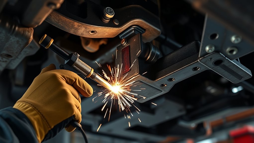
Tack the crossmember at both ends once you have confirmed alignment, clearance, bolt-hole position, and driveline angle. Tack welding is only meant to hold the part while you recheck the setup, so use short, controlled tacks that do not overheat the metal.
After each tack, check the assembly for movement. Make sure the transmission is still supported, the mount is not twisted, and the crossmember remains square to the frame. If the crossmember moved, cut the tack and correct the fit before you add more weld.
Let the tacks cool, then inspect them for sound fusion and a clean bond. Weak tack welds can break during final welding and let the crossmember pull out of position.
Weld the Crossmember Without Warping It
With the crossmember tacked and the driveline still aligned, start the final welds only after one more fit check. Clean every joint to bare metal before welding because oil, paint, rust, and undercoating can trap gas in the weld and weaken the bead.
Use short weld sections with cooling pauses instead of one long overheated pass. Move from side to side and alternate weld locations so heat does not pull the crossmember in one direction. If the metal warms too fast, stop and let it cool naturally. Do not quench the weld with water because rapid cooling can add stress.
- Verify fit and clearance before each weld section.
- Use the correct wire, shielding gas, voltage, and wire speed for the metal thickness.
- Weld only the joint areas required by the crossmember design or kit instructions.
- Let each section cool before welding the opposite side.
- Check alignment and driveline angle again after cooling.
When the welds are complete, let the crossmember cool fully before removing supports or tightening final hardware. Thermal movement can shift the part slightly as it cools, so measure again before you call the job finished.
Reinforce the Mounting Tabs for Torque
Reinforce the mounting tabs only when the design, swap kit, or fabrication plan calls for it. Thicker-gauge tabs, clean fit-up, and gussets can help the mount handle torque, but extra metal in the wrong place can also block clearance, create stress risers, or make future service harder.
Use clean, square cuts and tight fit-up. Add fillet welds along the edges to spread load, and use gussets where torque could twist the tabs. For hard launches, sticky tires, towing, or boosted setups, reinforcement may be worth adding before the final paint and assembly.
| Upgrade | Purpose | Result |
|---|---|---|
| Thicker steel tabs | Increase load capacity | Less flex at the mount |
| Fillet welds | Spread torque loads | Stronger joint edges |
| Gussets | Resist twisting | Better rigidity under load |
After you weld, inspect each joint for cracking, undercut, overlap, or separation. If a tab shifted or pulled during welding, fix it before you install the transmission mount permanently.
Test Fit the Transmission Before Final Welds
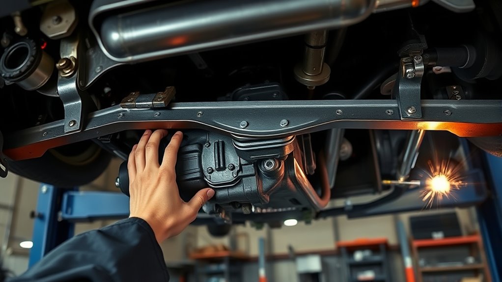
With the transmission installed or fully mocked up, verify clearance around the crossmember before you weld anything solid. The crossmember should support the transmission mount cleanly without forcing the mount, twisting the transmission case, or pulling the drivetrain sideways.
Bolt the mount in place, make any needed adjustments, and confirm the crossmember’s final position, level, and angle. Only then should you tack it for final welding.
Verify Transmission Clearance
Before you finalize any welds, test fit the transmission and verify that the crossmember clears the oil pan, converter bolts, exhaust, driveshaft, shift linkage, cooler lines, and nearby wiring. Keep the crossmember loose enough during mock-up so you can measure and adjust without fighting the frame.
- Check exhaust paths and other interference points.
- Use spacers or shims only where the mount or kit design allows them.
- Confirm the crossmember still allows engine and pinion angle adjustment.
- Check that the rubber or polyurethane transmission mount is not crushed or side-loaded.
If anything binds, correct it now. Small adjustments during test fit protect your welds, your drivetrain, and your time.
Confirm Final Crossmember Position
Once the transmission is securely mounted, test fit the crossmember and confirm its final position before any final welds are made. The drivetrain should be fully supported so you can measure accurately.
Check clearance at the transmission case, mount, exhaust path, driveshaft, and floor. Leave room for normal drivetrain movement under load. If needed, use the correct mount or shim package to dial in the engine and pinion angle alignment.
Install all hardware by hand, then verify the bolt holes line up without forcing anything. Make sure the crossmember sits square, level, and free of obstructions.
If you make any adjustment, mark it now so you can repeat the setup during final welding.
Inspect Welds and Check Clearance
Inspect the welds closely with bright light after they cool. Look for cracks, porosity, undercut, uneven tie-in, missed edges, or areas where the weld sits on top of the metal without fusion. If a weld looks cold, porous, or cracked, grind it out and repair it before the vehicle is driven.
Then verify clearance between the crossmember and transmission. Nothing should touch during engine movement or load transfer. Use a straight edge, tape measure, and angle finder to confirm the crossmember is not skewed.
- Check every weld seam for continuity and solid tie-in.
- Measure clearance around the exhaust, oil pan, driveshaft, and lines.
- Prime and paint bare metal after inspection to reduce corrosion.
- Torque all crossmember and transmission mount fasteners to the vehicle or mount manufacturer’s specs.
- After a short test drive, recheck bolt tightness, clearance, and vibration.
If you spot interference, correct it before regular driving. A careful final inspection protects the weld, preserves fitment, and keeps the drivetrain from fighting the chassis.
Troubleshooting After Welding
If the vehicle vibrates, binds, or makes new noises after the crossmember is welded, do not assume the welds are the only issue. Most problems come from fit, alignment, or clearance changes during welding and cooling.
- Vibration at speed: Recheck transmission output angle, driveshaft angle, and pinion angle at ride height.
- Clunk on acceleration: Inspect the transmission mount, crossmember bolts, exhaust contact, and driveshaft slip yoke clearance.
- Porous welds: Grind out the bad weld, clean the metal better, check shielding gas flow, and reweld with correct settings.
- Crossmember pulled out of square: Support the drivetrain, cut the problem weld if needed, realign, tack, and weld in shorter alternating sections.
- Mount holes no longer line up: Do not force the bolts. Loosen the setup, correct the crossmember position, and verify the mount is not preloaded.
Note: If the crossmember welds support a race car, towing vehicle, off-road build, or high-power swap, have the final work inspected by a qualified welder or fabricator before hard use.
Frequently Asked Questions
Does the crossmember hold up the transmission?
Yes. The transmission crossmember supports and locates the transmission mount. It helps control drivetrain movement, keeps the transmission at the correct height, and helps maintain proper driveshaft and pinion angles.
Can a bell housing be welded?
Sometimes, but it is usually a specialist repair. Bell housings may be cast aluminum, cast iron, or another material, and heat can distort the mounting face or alignment bore. For most DIY repairs, replacement or professional welding and machining is safer than welding it in place.
Is there a way to join metal without a welder?
Yes, metal can be joined with bolts, rivets, structural adhesive, or metal-bonding epoxy, but those options are not a safe substitute for welding a structural transmission crossmember unless the design specifically calls for them. Use mechanical fasteners or adhesives only where they are rated for the load.
What is a transmission crossmember for?
A transmission crossmember supports the transmission mount, ties the drivetrain support into the frame or chassis, and helps keep the transmission output shaft aligned with the driveshaft and rear axle. A poor crossmember setup can cause vibration, mount failure, cracked tabs, or exhaust and driveshaft clearance problems.
Should I weld the crossmember to the frame or bolt it in?
Use the design intended for your vehicle or swap kit. Many crossmembers are bolted in so the transmission can be serviced later. If the design requires welded tabs or brackets, weld the brackets carefully while keeping the removable crossmember serviceable when possible.
Conclusion
When you weld a transmission crossmember, you are locking in drivetrain support and geometry. Clean the metal, support the vehicle safely, mock up the transmission at ride height, measure the driveline angles, and tack the crossmember before final welding. Use short controlled welds, let the metal cool, and inspect every bead before paint and final assembly. A careful install helps prevent vibration, cracked tabs, mount preload, and costly rework later.
Sources
- OSHA 1910.252 General Requirements — fire prevention, PPE, ventilation, and hot-work precautions for welding and cutting.
- OSHA Welding, Cutting, and Brazing Hazards and Solutions — welding hazards including fumes, UV radiation, burns, electrical shock, and PPE.
- CDC/NIOSH Welding Fumes and Manganese — health risks from welding fumes and manganese exposure.
- Spicer Driveline Operating Angle Calculator — measuring U-joint operating angles and driveline angle guidance.




