
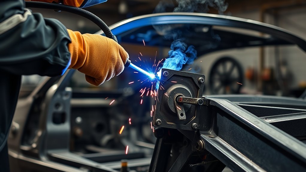
Welding a motor mount to a car frame is an advanced fabrication job because the bracket must hold engine weight, resist torque, control vibration, and keep the drivetrain aligned. Before you strike an arc, identify the frame material, confirm that welding is allowed at the chosen location, support the engine and vehicle securely, and follow the vehicle maker’s repair or body-builder procedure. If the chassis is rusted, unibody, aluminum, hybrid, electric, or built with high-strength steel, the safest approach is to use a qualified automotive fabricator.
Quick Answer
You can weld a fabricated steel motor-mount bracket to an approved steel frame location when the material, bracket design, alignment, weld size, and procedure are correct. Clean the joint, mock up the complete drivetrain, tack the bracket, recheck every clearance, then finish-weld and inspect it according to the vehicle-specific plan.
Key Takeaways
- Check the OEM repair information and identify the frame material before grinding, drilling, or welding.
- Weld the approved steel bracket or reinforcement, not the rubber or polyurethane isolator.
- Mock up the engine, transmission, crossmember, exhaust, steering, cooling system, and driveline before final welding.
- Place balanced tack welds first so you can correct alignment without cutting out a completed joint.
- Choose wire, gas, settings, weld size, and pass sequence for the measured material and joint instead of using universal settings.
- Inspect the welds, restore corrosion protection, scan the vehicle when required, and do not drive until the installation is verified.
At a Glance
| Time Required | Several hours for a straightforward mock-up and fabrication job; longer when rust repair, custom brackets, poor access, or drivetrain changes are involved |
| Difficulty | Advanced automotive fabrication and safety-critical welding |
| Tools Needed | Suitable welder, shielding gas and filler when required, grinder, clamps, measuring tools, angle finder, engine hoist or support bar, jack stands, welding PPE, ventilation, welding blankets, and fire extinguisher |
| Cost | Varies widely by vehicle, bracket design, access, materials, disassembly, rust, inspection requirements, and local labor; obtain a vehicle-specific written quote |
Warning: A motor-mount bracket is a safety-critical load point. Welding in the wrong place can weaken a frame or unibody, damage electronics, ignite hidden sealer or insulation, harm fuel or brake lines, and alter crash performance. Follow the vehicle maker’s procedure, use proper hot-work controls, and hire a qualified automotive fabricator when the material or joint design is uncertain.
What Should You Check Before Welding a Motor Mount?
Start by identifying what the bracket will attach to. The word “frame” may refer to a full body-on-frame rail, a removable subframe, a crossmember, or a structural unibody section. These parts do not share one welding procedure.
Look up the vehicle maker’s repair information or body-builder guide before you remove a coating or drill a hole. Some locations may permit welding, while others require a replacement section, bolt-on bracket, plug welds, specific reinforcement, or a different joining process. High-strength steel and aluminum can lose important properties when heated outside an approved procedure.
Inspect the proposed attachment area for rust, cracks, collision damage, previous repairs, thin metal, overlapping panels, hidden reinforcements, wiring, fuel lines, brake lines, seam sealer, foam, carpet, sound deadener, and nearby electronic modules. Do not weld a motor mount onto weakened or unknown metal.
Note: In most custom installations, you weld a fabricated steel frame-side bracket or reinforcement plate. The rubber or polyurethane isolator remains removable and should not be exposed to welding heat. Cast engine-side brackets require separate material identification and a qualified procedure.
Support the vehicle on rated jack stands or a lift placed at approved points. Support the engine and transmission with a hoist, support bar, or stable fixture. Never rely on a hydraulic floor jack as the only support while measuring or welding.
What Tools Do You Need to Weld a Motor Mount?
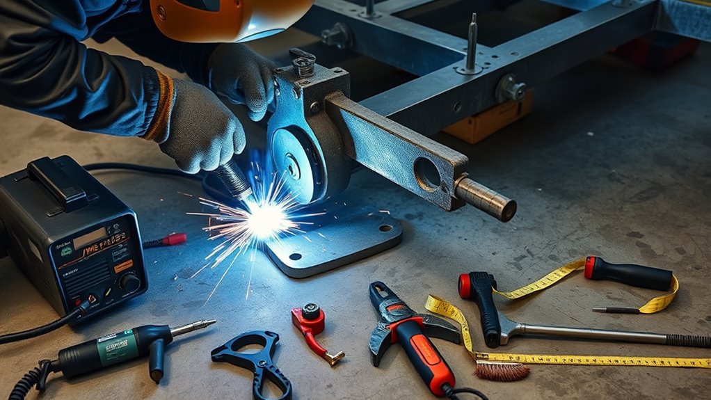
Use a welder that is rated for the measured base-metal thickness, joint position, filler diameter, and required duty cycle. Do not choose a machine only because it belongs to a certain amperage class. Review the machine’s setup chart and confirm its output range before you begin.
For many clean mild-steel brackets, ER70S-6 solid wire with an argon and carbon-dioxide shielding-gas mixture is a practical GMAW option. However, .030-inch wire, .035-inch wire, straight carbon dioxide, C25 gas, and other combinations serve different thicknesses and transfer modes. Select the consumable and gas from the procedure, filler-metal data, and welder chart. Test the setup on scrap that matches the real joint before welding the vehicle.
Your basic setup may include:
- A suitable MIG/GMAW or TIG/GTAW machine and correct power supply
- Compatible filler wire or rod, contact tips, drive rolls, regulator, and shielding gas
- Angle grinder, flap discs, burrs, wire brushes, and metal-cutting tools
- Heavy clamps, magnetic squares, temporary braces, and a stable fabrication fixture
- Tape measure, straightedge, calipers, angle finder, level, plumb line, and marking tools
- Engine hoist, support bar, transmission jack, rated stands, and wheel chocks
- Auto-darkening welding helmet, safety glasses, hearing protection, leather gloves, and flame-resistant clothing
- Local fume extraction or suitable ventilation
- Welding blankets, spark shields, and an immediately available fire extinguisher
- Drill press or hand drill when the approved bracket design includes accurately located bolt holes
A stable fixture and repeatable measurements matter as much as the welder. If the bracket moves during tacking, the engine position moves with it.
Follow proper safety precautions for coated or galvanized metal. Remove hazardous coatings from the heat-affected area and use effective ventilation. Outdoor work alone does not guarantee that fumes stay out of your breathing zone.
Products Worth Considering

A brand new 150Amp 10ft Replacement Mig gun for YESWELDER MIG-205DS Welder.
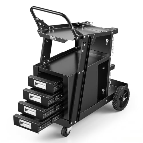
Strong Weight Capacity: VEVOR 2-tier welding cart can effortless handle various heavy loads, with 265LBS maximum static weight capacity and 220LBS maximum dynamic weight capacity. Heavy duty welder cart is suitable for a variety of welding tasks such as manual welding, gas shielded welding, and argon arc welding.

6-IN-1 Multifunctional Welder Machine: This 6-in-1 multi welder supports FLUX MIG, GAS MIG, PLASMA CUTTING, HF TIG, and STICK,SPOT welding, provide a comprehensive solution for a wide range of welding and cutting tasks, suitable for both home DIY and industrial projects.
How Do You Prep the Frame and Mount?
Preparation begins with material identification, not grinding. Confirm that the frame section and bracket are weldable with the chosen process. Do not apply mild-steel settings to cast iron, cast aluminum, high-strength steel, or an unknown alloy.
Remove paint, rust, scale, undercoating, seam sealer, oil, grease, adhesive, and plating from both parts. Clean a wide enough area to keep coatings outside the weld and heat-affected zone. Check the opposite side of the panel or rail because sparks and transferred heat can ignite hidden foam, carpet, sound deadener, or sealer.
Use a dedicated wire brush, flap disc, or grinder until you reach sound metal. Cleaning does not repair deep pitting or thin steel. If corrosion remains after the surface is cleaned, measure and inspect the section before deciding whether it needs replacement or reinforcement.
Measure the actual frame and bracket thickness. Fit the bracket tightly against the intended reinforcement or mounting surface. Wide gaps make heat control and weld size harder to manage. Bevel an edge only when the approved joint design calls for a groove or added access to the root. Do not bevel thin structural metal by habit.
Warning: Do not use chlorinated brake cleaner or another chlorinated solvent near arc welding. Ultraviolet radiation and heat can react with chlorinated vapors and create highly toxic gases. Use a residue-free cleaner approved for weld preparation, follow its safety data sheet, and let the area dry completely.
Pro Tip: Prepare a scrap coupon with the same material thickness, joint orientation, gap, wire, gas, and welding position. A flat bead on unrelated scrap does not prove that the real vertical or overhead joint is set correctly.
Good metal cleaning and fit-up reduce porosity, cold lap, and rework. Keep the cleaned surfaces dry and handle them with clean gloves so oil does not return to the joint.
How Do You Position a Motor Mount Properly?
Mock up the engine and transmission as a system. Install the transmission mount or crossmember, bellhousing, oil pan, starter, exhaust manifolds or headers, and any parts that affect position. Supporting the engine alone at a guessed angle can move the transmission output, shifter, driveshaft, exhaust, and cooling package out of place.
Set the engine centerline and fore-aft position from the vehicle or swap design. Check side-to-side level where the engine design calls for it, then set the transmission and driveline geometry from the complete installation. Do not assume that both brackets must look identical or sit at the same height. Some chassis and engine packages use intentionally different left and right brackets.
Before welding, confirm clearance around:
- Steering shaft, steering box or rack, and full steering travel
- Front axle, differential, suspension, and full bump and droop travel
- Oil pan, drain plug, oil filter, starter, and service points
- Exhaust manifolds, headers, catalytic converters, and heat shields
- Firewall, transmission tunnel, hood, cowl, radiator, fan, and accessory drive
- Fuel lines, brake lines, wiring harnesses, sensors, hoses, and electronic modules
- Transmission crossmember, shifter linkage, transfer case, driveshaft, and pinion geometry
Leave enough room for normal engine movement under torque. The rubber or polyurethane isolator should sit in its intended neutral position without being twisted, compressed sideways, or forced into alignment by the bracket bolts.
Confirm the engine centerline, transmission position, mount preload, driveline geometry, and service clearance before you mark the final bracket location.
If an engine-side bracket or adapter appears to be cast, identify the alloy before modifying it. Do not rely on general advice about preheating cast iron as a substitute for a qualified cast-metal procedure. A purpose-built bolt-on or fabricated steel adapter is often the safer serviceable choice.
How to Weld a Motor Mount to a Car Frame Step by Step
- Confirm that welding is allowed. Identify the chassis section and material, then review the OEM repair information, body-builder guide, or engineered swap instructions. Stop if the location, alloy, or approved joining method is uncertain.
- Make the vehicle safe. Follow the vehicle maker’s battery-disconnection and system-shutdown sequence. Protect or remove nearby modules, wiring, batteries, sensors, fuel lines, brake lines, hoses, foam, sealer, trim, glass, carpet, and insulation. A hybrid or EV may require high-voltage de-energization by a trained technician.
- Control the hot-work area. Remove combustibles, cover surfaces that cannot be removed, place an extinguisher within reach, inspect the opposite side of the welding area, and assign a fire watch when hidden materials or poor access create added risk.
- Support the chassis and drivetrain. Chock the wheels, support the vehicle at approved points, and hold the engine and transmission with stable equipment. Do not work beneath a drivetrain supported only by a floor jack.
- Prepare and fit the parts. Remove coatings and contamination, inspect for sound metal, measure thickness, shape the bracket, and create tight contact with the approved reinforcement or attachment surface.
- Place the welding return correctly. Attach the return clamp to clean metal as close to the welding point as practical. Arrange the circuit so welding current does not pass through bearings, hinges, wiring, modules, or other sensitive paths.
- Tack the bracket. Place small, balanced tacks at separated points. Recheck the engine centerline, mount preload, transmission, driveline, steering, exhaust, cooling, suspension, hood, firewall, and service access.
- Prove the welding setup. Use matching scrap coupons to confirm polarity, wire, gas, voltage, wire-feed speed, travel speed, position, fusion, and heat control. Correct the setup before welding the chassis.
- Complete the approved weld sequence. Remove or shield heat-sensitive isolators. Weld in the specified position, size, and sequence. Alternate locations when appropriate to manage movement and allow natural cooling. Do not add passes merely to make the bead look larger.
- Inspect and finish the installation. Verify dimensions, inspect every weld, correct defects properly, restore coatings and cavity protection, torque removable mount hardware to specification, reconnect systems in the OEM sequence, and perform any required diagnostic scan or calibration.
Note: Disconnecting the battery does not replace correct return-clamp placement, OEM electrical precautions, removal of nearby components, or high-voltage isolation on an electrified vehicle.
Should You Tack-Weld Before Final Welding?
Yes. Tack welding holds the bracket in place while leaving a realistic chance to correct the installation. A completed weld is much harder to remove without thinning or damaging the frame.
Place the first tacks at balanced, separated points. Avoid completing one side while the opposite side remains loose because shrinkage can rotate or pull the bracket. Make each tack large enough to hold the mock-up safely, but remember that tacks are temporary unless the final procedure specifically incorporates them into the finished weld.
After tacking both sides, carefully transfer the engine’s weight to the isolators and recheck every reference measurement. Confirm that the isolators are not twisted or side-loaded. Install or mock up the transmission crossmember, steering shaft, exhaust, oil filter, starter, radiator, fan, accessory drive, shifter, and driveshaft before you commit.
If a clearance or alignment problem appears, stop and correct the bracket while the tacks can still be removed with limited damage. Do not force bolts through misaligned holes or use the mount fasteners to pull the drivetrain into position.
Note: Tack welds are not proof of final strength. Keep the engine supported until the complete joint has cooled, passed inspection, and received all required hardware.
What Welding Method Works Best for Motor Mounts?
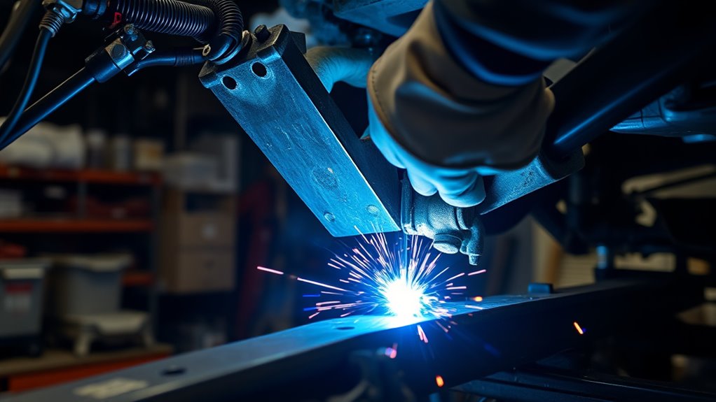
For a fabricated mild-steel frame-side bracket, MIG or GMAW is often practical because it provides controlled wire feeding and works well in automotive fabrication when the machine and procedure match the joint. TIG or GTAW can provide precise control and clean access on suitable material, but it requires excellent fit-up, cleanliness, and operator skill.
The best process is the one approved for the actual material, thickness, joint, position, and vehicle structure. Do not choose MIG, TIG, or flux-cored welding only because one process is familiar. Some OEM repair procedures require a particular process, plug-weld size, weld spacing, reinforcement, or heat limit.
ER70S-6 wire and C25 shielding gas are common options for clean mild steel, but they are not automatic requirements for every mount. Use the filler manufacturer’s data, the welding-machine chart, and an approved procedure. Proper shielding-gas coverage helps prevent porosity, while correct wire, polarity, and machine setup help the arc fuse both sides of the joint.
Welding position also matters. A vertical joint may require a different technique, travel direction, voltage, and wire-feed speed than a flat coupon. Use the direction and progression required by the procedure and proven on matching practice material.
Do not assume that one pass is enough or that adding another pass automatically makes a bracket stronger. The correct pass count follows the required weld size, groove preparation, fit-up, base-metal thickness, heat input, and observed fusion. If the first pass contains porosity, slag, cracks, or lack of fusion, remove the defect instead of covering it.
Pro Tip: Do not grind a structural weld flush just to improve its appearance unless the bracket design or repair procedure requires it. Heavy cosmetic grinding can reduce the effective weld size and hide defects.
Products Worth Considering

Welding Easy and Quick: AWS E71T-GS 030” Flux Core welding wire (The actual Net Weight of Wire is 2LB), no need for shielding gas, install it then you can welding all positions, single and multi pass welding. Great for T-joints, butt welds & lap welds.

SMOOTH, EASY TO RUN: This ER70S-6 MIG wire runs clean and steady, helping you keep a smooth arc without constantly adjusting your machine. It handles mild steel with light rust or mill scale without giving you trouble

ER70S-6 MIG WIRE: It's the most common wire of the copper-coated mild steel GMAW (MIG) wires for single or multiple pass welding.
How Do You Control Heat When Welding a Motor Mount?
Heat control begins with the correct process, fit-up, filler, settings, and travel speed. A cold bead may sit on the surface without fusing. Excess heat can cause burn-through, distortion, damaged coatings, weakened heat-sensitive material, or a fire inside a boxed section.
Use the approved weld sequence and move between separated areas when the design allows it. Short sections can help control movement, but they still need proper fusion at every start and stop. Watch the puddle wet into both sides of the joint rather than judging the weld only by bead height.
Allow the joint to cool naturally between stages when needed. Do not quench a hot structural weld with water. Sudden cooling can introduce stress, conceal the true cooling behavior, and damage nearby parts.
Keep heat-sensitive isolators, hoses, seals, modules, and coatings away from the welding zone. Remove the rubber or polyurethane mount when possible. If it cannot be removed during a specific stage of mock-up, use an effective heat shield and monitor it closely, then remove it before final welding whenever the design permits.
Warning: Sparks, molten metal, and transferred heat can reach the opposite side of a frame rail, floor, firewall, or boxed section. Inspect both sides during the job and continue checking for smoke, heat, or smoldering material after welding stops.
How Do You Check Alignment and Weld Quality?
Check alignment with repeatable measurements, not only a bubble level. Record the engine centerline, crankshaft or transmission reference, mount locations, crossmember position, driveline relationship, and key body or frame reference points before final welding. Compare the measurements again after the joint cools.
Inspect the fit-up before welding. The bracket should contact the intended surface as designed, without being pulled into place by mount bolts. Confirm that the isolator remains neutral and that the engine can move within its normal range without contacting the body, steering, suspension, exhaust, cooling package, or accessories.
Good weld inspection begins before the arc starts. Correct material, joint design, fit-up, access, and settings prevent defects that appearance alone cannot rule out.
After welding, clean the joint enough to see the bead without thinning it. Inspect for:
- Cracks in the weld, crater, toe, tack area, or heat-affected metal
- Visible porosity or clustered pinholes
- Undercut along either edge
- Cold lap, lack of tie-in, or a bead sitting on top of the base metal
- Burn-through, missing sections, or an undersized weld
- Excessive reinforcement, irregular stops and starts, or unfilled craters
- Arc strikes outside the intended weld area
- Bracket movement, frame distortion, or changed drivetrain measurements
A casual push, pry, or engine-rocking test does not prove that a weld is sound. If the joint is safety-critical, difficult to see, or questionable, have it inspected by a qualified welder, automotive fabricator, engineer, or inspector. Appropriate nondestructive testing may be used when the project requirements justify it.
Post-Weld Checklist
- Confirm all dimensional references after the joint has cooled.
- Verify the engine and transmission mounts are not twisted or side-loaded.
- Inspect the weld and surrounding metal under good lighting.
- Remove spatter that could cut wiring or interfere with parts without reducing the weld.
- Restore primer, seam sealer, paint, undercoating, and internal cavity protection as appropriate.
- Reinstall heat shields, hoses, lines, wiring clips, trim, insulation, and electronic parts.
- Torque all removable mount and crossmember hardware to the correct specification.
- Reconnect batteries and modules in the OEM sequence.
- Perform pre- or post-repair scanning, clearing, calibration, or relearn procedures when required.
- Check for fluid, fuel, exhaust, brake, steering, electrical, and cooling problems before driving.
What Problems Can Happen When Welding Motor Mounts?
A poor motor-mount installation may cause vibration, repeated mount failure, cracked brackets, drivetrain bind, exhaust contact, steering interference, cooling problems, driveshaft vibration, frame distortion, or fire and electrical damage.
Motor-Mount Welding Troubleshooting
| Problem | Likely Cause | Corrective Action |
|---|---|---|
| Bracket moves after tacking | Weak or unbalanced tacks, poor clamping, or engine support movement | Stop, support the drivetrain, remove the affected tacks, reset the measurements, improve the fixture, and tack at balanced points. |
| Porosity | Contamination, wind, poor gas flow, a leak, long stickout, or blocked nozzle | Remove the defective metal, clean the joint, repair the gas problem, protect the arc from drafts, and prove the setup on matching scrap. |
| Bead sits high with poor edge tie-in | Low heat, fast travel, wrong gun angle, poor access, contamination, or incorrect settings | Do not cover it. Remove the defective weld, correct the cause, and repeat the coupon test before rewelding. |
| Burn-through or melted frame edge | Thin or corroded steel, excessive heat, a wide gap, or poor joint design | Stop and assess the remaining base metal. Repair or replace the section under an approved procedure instead of filling a weakened hole blindly. |
| Excess vibration after installation | Mount preload, wrong engine position, rigid contact, mismatched isolators, or driveline misalignment | Do not keep driving. Recheck mount neutrality, engine centerline, transmission position, clearances, driveshaft geometry, and bracket dimensions. |
| Bracket or weld cracks | Poor fusion, undersized weld, stress concentration, weak material, incorrect bracket design, or excessive drivetrain movement | Remove the vehicle from service and have the material, joint, bracket design, and related mounts inspected before repair. |
Do not treat a cracked mount as an isolated cosmetic defect. The crack may be a symptom of drivetrain movement, a failed transmission mount, chassis flex, poor bracket geometry, collision damage, or an engine position that overloads the joint.
When Should You Hire a Professional Welder?
Hire a qualified automotive fabricator when you cannot identify the material, establish the correct joint, perform representative coupon tests, or inspect the final weld with confidence. Motor mounts are not a suitable first structural welding project.
Professional help is especially important when:
- The vehicle has a unibody, advanced high-strength steel, aluminum structure, or bonded construction
- The vehicle is hybrid or electric
- The attachment area is rusted, cracked, collision-damaged, thin, or previously repaired
- The bracket or engine-side component is cast iron, cast steel, or cast aluminum
- The mount is part of a custom engine swap with no proven bracket design
- The vehicle will be raced, towed, inspected, used off-road under high load, or driven on public roads
- The engine produces substantially more torque than the original drivetrain
- Welding access is vertical, overhead, enclosed, or close to fuel, brake, electrical, or interior systems
- Local inspection, insurance, registration, sanctioning-body, or roadworthiness rules apply
A qualified shop can also determine whether a bolt-in bracket, reinforcement plate, replacement crossmember, or engineered cradle is safer and easier to service than welding directly to the existing structure.
Frequently Asked Questions
Can you weld engine mounts?
Yes, a fabricated steel frame-side motor-mount bracket can be welded when the vehicle structure, material, bracket design, weld size, process, and alignment have been verified. Do not weld the rubber or polyurethane isolator, and do not weld unknown cast or structural material without an approved procedure.
What type of welding is used on car frames?
MIG or GMAW is common for many approved mild-steel chassis and bracket jobs, while TIG or GTAW may be used for suitable custom fabrication. The correct process depends on the vehicle maker’s procedure, frame material, joint design, thickness, position, and required weld size.
Is it safe to weld on a vehicle frame?
It can be safe only when welding is allowed at that location and the person doing the work follows the material, structural, electrical, hot-work, and vehicle-specific procedures. Welding the wrong frame or unibody area can weaken the structure, damage electronics, start a hidden fire, or affect crash performance.
How much does it cost to get a chassis or motor mount welded?
There is no reliable nationwide price. The cost depends on the vehicle, bracket design, access, rust, disassembly, materials, mock-up time, electrical protection, inspection, coating, and local labor. Ask for a written quote that states what fabrication, welding, inspection, and finishing work is included.
Should motor mounts be bolted or welded?
The removable rubber or polyurethane mount is normally bolted so it can be serviced. A custom frame-side bracket may be bolted, welded, or use both methods depending on the chassis and engineered design. Do not replace a proven bolt-in system with a welded bracket without checking load paths and service access.
Can you weld a motor mount to a rusty frame?
No. Grinding off surface rust is not enough when the steel is pitted, thin, cracked, soft, or perforated. The attachment point must be sound and thick enough for the approved joint. Repair or replace weakened structure before adding the motor-mount bracket.
Do you need to disconnect the battery before welding on a car?
Follow the vehicle maker’s exact disconnection procedure. Many repair procedures require the 12-volt battery to be disconnected and vehicle systems to be shut down. Battery disconnection is only one step. You may also need to remove or protect nearby modules, place the welding return close to the weld, and de-energize a hybrid or EV high-voltage system through a trained technician.
Can you weld a motor mount with the rubber isolator installed?
Remove the rubber or polyurethane isolator before final welding whenever the design allows it. Welding heat can damage the isolator, change its stiffness, release fumes, or start a fire. Use the isolator during mock-up only as needed, then remove or fully protect it before completing the weld.
Can you weld a motor mount directly to a unibody?
Only when the vehicle maker or an engineered fabrication plan permits that attachment and specifies the material, reinforcement, joining method, and location. A unibody may contain thin layered panels, high-strength steel, adhesives, foam, and crash-management structures. This work should normally be handled by a qualified automotive fabricator or certified collision-repair technician.
Conclusion
Welding a motor mount to a car frame is not just a matter of placing a bracket and running a bead around it. The installation depends on sound material, an approved attachment point, a stable drivetrain mock-up, neutral mount position, correct weld design, controlled heat, and careful inspection.
Check the vehicle maker’s information before you begin, protect the electrical and fuel systems, tack before final welding, and verify every clearance after the joint cools. If the structure, alloy, weld quality, or bracket design is uncertain, stop and use a qualified automotive fabricator. The cost of professional work is small compared with the damage a failed or misaligned engine mount can cause.
Sources
- I-CAR: Vehicle Protection When Welding — supports battery disconnection, system shutdown, removal of nearby electronics, and protection from fire and welding damage.
- Volvo Car USA: Electric Vehicle Welding Position Statement — supports 12-volt disconnection, trained high-voltage de-energization, nearby work-return placement, and removal of electronic or battery components when required.
- OSHA 1926.352: Fire Prevention — supports removal or protection of combustibles, immediate fire-extinguishing equipment, opposite-side precautions, and fire-watch controls.
- OSHA: Controlling Hazardous Fume and Gases During Welding — supports coating removal, fume control, local exhaust, ventilation, and respiratory-protection guidance.
- OSHA 1910.252: Welding, Cutting, and Brazing Requirements — supports ventilation requirements and keeping chlorinated cleaning vapors away from welding operations.
- Lincoln Electric SuperArc L-56 ER70S-6 Data — supports ER70S-6 classification, available wire sizes, shielding-gas options, and parameter-specific consumable selection.




