
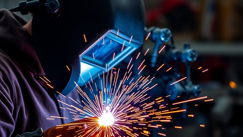
MIG welding transfer modes describe how molten filler metal moves from the continuously fed wire across the arc and into the weld pool. The transfer you produce changes heat input, puddle control, spatter, penetration, deposition rate, welding position, and bead appearance. Your shielding gas, wire, voltage, amperage, wire feed speed, stickout, base metal, and power-source waveform all affect the result.
Quick Answer
The four commonly taught MIG operating modes are short circuit, globular, spray, and pulsed spray. Choose short circuit for thin metal and positional work, conventional spray for thicker flat or horizontal welds, and pulsed spray when you need spray-like transfer with better heat and puddle control. Globular transfer is usually a transition region to avoid.
Key Takeaways
- Short circuit transfer uses lower heat, freezes quickly, and works well on thin material and out-of-position joints.
- Globular transfer produces large, irregular droplets and heavy spatter. It is generally a transition region rather than a preferred production mode.
- Spray transfer gives high deposition, smooth axial transfer, and little spatter, but it needs suitable argon-rich gas, sufficient current, and a heat-tolerant joint.
- Pulsed-spray transfer uses peak and background current to control one or more droplets per pulse while reducing average heat.
- No universal voltage, amperage, or wire-feed setting creates a mode on every machine. Start with the manufacturer’s chart or qualified procedure and confirm the actual arc behavior.
At a Glance
| Best Thin-Metal Mode | Short circuit transfer |
| Best High-Deposition Mode | Conventional spray transfer |
| Best Heat-Control Mode | Pulsed-spray transfer |
| Most Spatter-Prone Mode | Globular transfer |
| Main Setup Factors | Wire type and diameter, shielding gas, voltage, current, wire feed speed, stickout, material thickness, joint design, position, and machine waveform |
What Are MIG Welding Transfer Modes?

Gas metal arc welding, or GMAW, joins metal with an electric arc between the workpiece and a continuously fed consumable wire. Shielding gas protects the arc and molten pool from the surrounding air. You can review the formal process description in the American Welding Society overview of GMAW.
Most shop guides discuss four operating modes: short circuit, globular, spray, and pulsed spray. This four-part model is useful for learning how the arc behaves. Formal terminology is slightly different, however. AWS identifies short-circuiting, globular, and spray as the three main transfer families, with pulsed spray treated as a spray-transfer subset. The AWS transfer-mode clarification also explains that the actual droplet behavior at the arc determines the transfer mode, not only the label selected on the power source.
A pulse button or synergic program does not prove that pulsed-spray transfer is occurring. The observed metal transfer at the arc determines the mode.
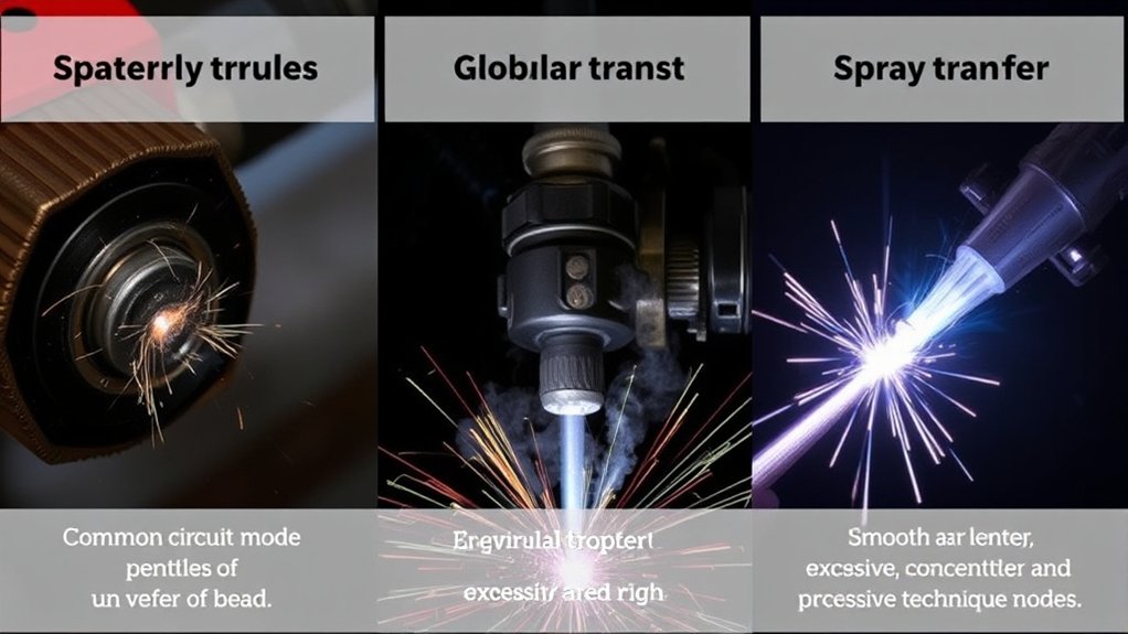
Short circuit transfer repeatedly touches the wire to the weld pool. Each contact creates a short circuit, the wire necks down, a small amount of metal transfers, and the arc reignites. It uses lower average heat than conventional spray transfer and gives you a quickly freezing puddle.
Globular transfer forms large, irregular droplets at the wire tip. Gravity, electromagnetic forces, and arc conditions move those droplets toward the pool, but transfer is less stable and more spatter-prone than spray. It commonly appears between stable short-circuit and spray settings.
Spray transfer moves fine droplets axially across the arc without the wire repeatedly contacting the pool. It requires enough current to exceed the spray transition point and a shielding gas that supports axial spray for the selected material and wire.
Pulsed-spray transfer alternates a high peak current with a lower background current. The peak helps detach a controlled droplet, while the background current maintains the arc with lower average heat than conventional spray. A capable pulse power source and a suitable program are required.
The transfer mode is only one part of a complete setup. Surface coating, joint preparation, shielding gas, and material type also matter. For example, MIG welding galvanized steel requires added fume precautions and careful removal or control of the zinc coating near the joint.
Note: Exact transition points vary with wire classification, wire diameter, shielding gas, stickout, base metal, polarity, machine design, and waveform. Treat every chart as starting guidance and confirm the result with test welds or a qualified welding procedure.
MIG Transfer Mode Comparison Table
| Transfer Mode | Best Use | Main Benefit | Main Limitation |
|---|---|---|---|
| Short Circuit | Thin metal, sheet metal, tack welds, root work where approved, and positional welding | Low heat and quick puddle freezing | Lower deposition and risk of incomplete fusion on heavier joints |
| Globular | Recognizing an unstable transition region or following a procedure that specifically permits it | Can deposit metal above the short-circuit range | Heavy spatter, irregular transfer, poor positional control, and added cleanup |
| Spray | Thicker material, flat or horizontal production welds, and smooth high-deposition beads | High deposition, good fusion, and little spatter | High heat, fluid puddle, gas restrictions, and limited positional use |
| Pulsed Spray | Heat-sensitive work, aluminum and stainless applications, lower-spatter production, and positional welding with an approved program | Controlled spray transfer at lower average current | Requires pulse-capable equipment, correct gas, and program-specific technique |
Products Worth Considering

Smooth Welding Experience: With ARCCAPTAIN ER4043 Aluminum Welding Wire, expect smooth and stable arc characteristics, ensuring easy control and excellent weld bead appearance.

ER4043 WELDING WIRE: A premium 5% silicon aluminum (AlSi5) filler metal designed for the MIG welding process. This composition delivers excellent fluidity and wetting characteristics, making it ideal for welding a wide range of aluminum alloys. It features a melting range of 1065°F to 1170°F, a density of 0.097 lbs/in³, and produces a consistent gray finish after anodizing.

ER4043 WELDING WIRE: A premium 5% silicon aluminum (AlSi5) filler metal designed for the MIG welding process. This composition delivers excellent fluidity and wetting characteristics, making it ideal for welding a wide range of aluminum alloys. It features a melting range of 1065°F to 1170°F, a density of 0.097 lbs/in³, and produces a consistent gray finish after anodizing.
Understanding Short Circuit Transfer: Benefits and Limitations
Short circuit transfer is the most common choice for thin steel, sheet metal, small gaps, and joints that cannot be placed flat. The wire contacts the weld pool many times each second. Each contact briefly extinguishes the arc, transfers metal, and starts the arc again. A stable setup often produces an even crackling sound.
Because the average heat and puddle size are lower than in spray transfer, short circuit helps reduce burn-through and distortion. The puddle also freezes quickly, which helps you weld vertically, overhead, and around awkward joints. These advantages make the mode useful for automotive panels, light fabrication, maintenance, and many root-pass applications when the procedure permits it.
The main concern is incomplete fusion. On thick material, a low-current short-circuit bead can look acceptable while failing to fuse into the joint faces or root. Poor work angle, long stickout, dirty metal, excessive travel speed, or an incorrect voltage and wire-feed balance can make the problem worse.
A stable electrical connection is essential. A loose or contaminated work clamp can cause arc interruptions and erratic transfer. Review the steps for checking a MIG welder that feeds wire but produces no stable arc if the wire feeds correctly but the arc repeatedly drops out.
| Benefit | Limitation |
|---|---|
| Useful on thin material | Lower deposition than spray transfer |
| Quick puddle freezing | Risk of incomplete fusion on thick joints |
| Works in flat, horizontal, vertical, and overhead positions | Can create more spatter than a stable spray arc |
| Lower burn-through risk | Needs a close voltage, wire-feed, inductance, and stickout balance |
Common solid-wire diameters for light and general GMAW include 0.023, 0.030, 0.035, and 0.045 inch, but no single range defines short-circuit transfer. ER70S-3 and ER70S-6 are common carbon-steel wire classifications. Your machine output, wire data sheet, shielding gas, and joint determine the usable range.
Many power sources provide an inductance, arc-control, or dynamics setting for short-circuit transfer. More inductance generally softens the current rise and can produce a wetter puddle, while less inductance can create a crisper arc. The control direction and scale vary by machine, so follow the owner’s manual rather than assuming that every dial works the same way.
Pro Tip: If a short-circuit bead looks tall, narrow, and cold, do not correct it only by slowing your travel. Check voltage, wire feed speed, inductance, stickout, work angle, joint preparation, and the work-clamp connection before welding the final part.
Globular Transfer: Characteristics and Applications
In globular transfer, large molten droplets form at the end of the wire and cross the arc irregularly. The droplets may be larger than the wire diameter, and they do not move in the fine axial stream seen in spray transfer. The result is usually a harsher arc, an uneven bead, and more spatter.
Globular transfer commonly appears when the voltage, current, or wire feed speed has moved above a stable short-circuit range but the setup has not reached stable spray transfer. It is strongly associated with carbon-steel welding under 100% CO2, because pure CO2 does not support the same conventional axial-spray behavior as a suitable argon-rich blend.
Although globular transfer can produce substantial heat and metal deposition, it should not automatically be treated as the preferred choice for thick steel. Modern manufacturer guidance often describes it as an unstable region to avoid when a cleaner short-circuit, spray, or pulsed process is available. If spatter is a recurring problem, review these MIG welding problems and spatter solutions.
Welding Process Overview
Globular transfer normally uses more voltage and current than low-end short-circuit transfer. Large droplets build at the wire tip before detaching. Gravity has a stronger effect on the droplet and molten pool than it does during fine axial spray, so the process is difficult to control vertically or overhead.
The mode can appear with different gases, but it is especially common when welding carbon steel with 100% CO2. CO2 is economical and can provide useful penetration, but it also creates a more forceful, reactive arc and more spatter than many argon-rich mixtures.
Material Thickness Suitability
General manufacturer training material often places handheld globular operation on steel around 1/8 inch or thicker. Treat that figure as a broad teaching guideline, not a universal minimum. Wire diameter, joint design, gas, machine output, travel speed, and procedure requirements can change the usable range.
Globular transfer is a poor choice for thin sheet because the larger droplets and added heat can cause burn-through, distortion, and an uneven bead. It is also a weak choice when low spatter, cosmetic appearance, positional control, or low cleanup time matters.
For stainless steel and aluminum, use the wire, gas, and transfer program recommended for the alloy. Do not assume that a carbon-steel CO2 setup will produce acceptable results on another material.
Typical Applications and Limitations
You may encounter globular transfer during repair work, training, older constant-voltage setups, or carbon-steel welding with pure CO2. A qualified procedure may also permit it for a defined application. Even then, keep the joint flat or in a horizontal fillet position whenever possible, and expect more cleanup.
The largest limitation is unstable droplet transfer. Excessive stickout, the wrong voltage-to-wire-feed balance, poor gas coverage, contaminated metal, or worn consumables can make the arc even less predictable. Instead of trying to make every job work in globular transfer, decide whether the correct solution is to return to stable short circuit, increase the setup into true spray transfer, or select an approved pulse program.
Best Practices for Managing or Avoiding Globular Transfer
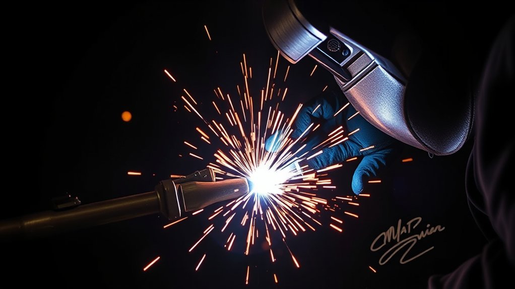
When a weld unexpectedly enters globular transfer, stop and identify why before continuing on the finished joint. The goal is usually to restore stable short-circuit transfer or move into a qualified spray or pulsed-spray program.
Begin with the basic setup. Clean the workpiece, attach the work clamp to clean bare metal near the joint, inspect the contact tip and liner, confirm the gas cylinder and flow, trim the wire, and maintain a consistent contact-tip-to-work distance. Then compare your voltage and wire feed speed with the manufacturer’s chart.
- Confirm that the shielding gas supports the transfer mode you want.
- Check whether the wire feed speed is too high for the selected voltage.
- Check whether the voltage is too high for stable short-circuit transfer but still below the spray range.
- Shorten excessive stickout and keep your torch movement steady.
- Keep globular welds flat or in a horizontal fillet position if a procedure specifically allows the mode.
- Test on scrap that matches the final material, thickness, joint, and gas.
- Inspect both toes of the weld and the root area for proper fusion.
- Use a qualified procedure for structural, pressure, vehicle-safety, or load-bearing work.
ER70S-3 and ER70S-6 are common solid wires for carbon steel, but wire classification alone does not determine the transfer mode. Use the wire manufacturer’s data, the machine chart, and a verified MIG welding wire-speed and voltage chart as starting information rather than as a substitute for testing.
Warning: Do not force globular transfer onto thin material to obtain more penetration. The added heat and large droplets can cause burn-through, distortion, heavy spatter, and an unreliable weld profile.
Understanding Spray Transfer: Efficiency and Best Practices
Conventional spray transfer sends a fine stream of molten droplets axially from the wire to the weld pool. The wire does not repeatedly short against the pool. When the current, voltage, gas, wire, and stickout are correct, the arc sounds smooth and produces a broad, fluid puddle with very little spatter.
Spray transfer offers high deposition, strong fusion, and a smooth bead. It is valuable in production welding, thicker fabrication, and long flat or horizontal joints where speed and appearance matter. The tradeoff is higher heat input and a fluid puddle that is difficult to hold vertically or overhead.
For carbon steel, conventional spray generally requires an argon-rich shielding gas. Manufacturer guidance commonly uses at least 80% argon as a starting rule, with mixtures such as 90% argon and 10% CO2 used in many spray and pulse applications. The exact approved gas depends on the wire, material, procedure, and power source.
Spray transfer also requires the current to rise above the transition current. Below that point, droplets may remain globular instead of becoming a fine axial spray. Transition current is not one fixed number. It changes with wire diameter, wire chemistry, gas composition, stickout, and machine characteristics.
Do not use standard spray transfer on thin sheet simply because it produces a smooth sound. The high heat and fluid puddle can cause burn-through or severe distortion. Pulsed spray may extend spray-like transfer to thinner sections, but only when the machine, program, gas, and procedure support it.
Flux-cored arc welding uses different wires and operating characteristics. Do not apply solid-wire spray settings to a flux-cored wire unless its data sheet and power-source program allow it. For that separate process, review these flux-core welding tips for beginners.
| Spray-Transfer Factor | Why It Matters |
|---|---|
| Argon-Rich Shielding Gas | Supports stable axial transfer for the selected material |
| Current Above Transition | Changes large irregular droplets into a fine spray stream |
| Wire Feed Speed | Controls current and deposition on a constant-voltage setup |
| Voltage and Arc Length | Affect bead width, stability, and spatter |
| Position and Fit-Up | Flat or horizontal placement helps contain the fluid puddle |
Pulsed-Spray Transfer Advantages for Precision Welding
Pulsed-spray transfer gives you many of the advantages of conventional spray while lowering average current. The power source rapidly alternates between a high peak current and a low background current. The peak detaches and propels a droplet, while the background maintains the arc without transferring the same amount of metal.
This controlled cycle can reduce spatter, distortion, and burn-through compared with conventional spray. It can also improve puddle control during positional welding. The result still depends on a correct pulse program, wire, gas, stickout, travel angle, and joint design. Read the Miller guide to pulsed GMAW for a manufacturer explanation of peak current, background current, gas choice, and technique.
Pulsed spray is especially useful for aluminum, stainless steel, carbon steel, and other applications where high deposition and a clean bead matter but conventional spray adds too much heat. It may also let you use a larger wire on material that would otherwise require a smaller wire, although this depends on the machine program and procedure.
Enhanced Heat Control
The lower average current in a pulse cycle can reduce puddle size and distortion. Faster travel may reduce total heat input further when the joint and procedure permit it. This can help on assemblies where fit-up, appearance, and dimensional control matter.
- Lower average current can reduce distortion compared with conventional spray.
- Controlled droplet detachment reduces spatter and cleanup.
- A consistent contact-tip-to-work distance helps the waveform perform correctly.
- Suitable travel speed can improve productivity without overheating the joint.
- Correct peak, background, arc-length, and trim settings stabilize the puddle.
Pulsed spray is useful when conventional spray is too hot but ordinary short-circuit transfer does not provide the deposition, fusion profile, or appearance required by the job.
Versatile Positioning Capabilities
Because the average heat and puddle fluidity can be lower than in conventional spray, pulsed spray can support vertical, overhead, and complex joints when the wire, machine program, and procedure are approved for those positions.
Do not assume every pulse program works in every position. Some programs target flat production welding, while others are designed for positional work. Follow the machine manual, wire data sheet, and WPS. Adjusting random pulse parameters without understanding their purpose can produce unstable transfer even though the display still says “pulse.”
Where Advanced MIG Waveforms Fit
Modern inverter welders may include controlled short-circuit, modified short-arc, pulse, double-pulse, or manufacturer-named waveform programs. These controls can improve root-pass behavior, spatter, heat input, or arc stability. They do not automatically create a new fundamental transfer family.
A controlled short-circuit waveform still belongs to the short-circuiting family when the wire repeatedly contacts the pool. Pulsed spray remains part of the spray family when droplets cross the arc without shorting. The actual transfer observed at the arc is more important than the marketing name on the control panel.
Flux-cored wires follow their own data sheets and process classifications. A machine may provide waveform control for some metal-cored or flux-cored products, but you should not substitute a flux-core settings chart for a solid-wire GMAW pulse procedure.
Choosing the Right MIG Welding Transfer Mode for Your Project
Choose the transfer mode from the job requirements rather than from the highest setting your machine can produce. Consider material thickness, alloy, joint type, welding position, fit-up, shielding gas, wire diameter, machine capability, appearance, deposition target, and procedure requirements.
- Use short circuit transfer for thin materials, automotive panels, tack welds, gap control, and positional joints where lower heat and fast puddle freezing help.
- Treat globular transfer as a warning region unless an approved procedure specifically calls for it. Large irregular droplets and heavy spatter usually mean you should adjust the setup.
- Use conventional spray transfer for thicker material in flat or horizontal positions when you need high deposition, strong fusion, and low spatter.
- Use pulsed-spray transfer when you need spray-like droplet transfer with lower average heat, less distortion, or improved positional control.
- Confirm the shielding gas before changing every electrical setting. A gas that works for short circuit may not support conventional spray.
- Match the wire to the material. Carbon steel, stainless steel, and aluminum require different wire classifications and gas choices.
- Follow the WPS for structural, pressure, safety-critical, or inspected work.
Your full setup also affects consistency. A clear helmet lens, comfortable torch position, stable work clamp, clean nozzle, smooth wire path, and secure workpiece help you maintain a steady arc. Properly fitted welding hood accessories may improve comfort and visibility, but they do not replace correct machine settings or safety-rated protective equipment.
Products Worth Considering
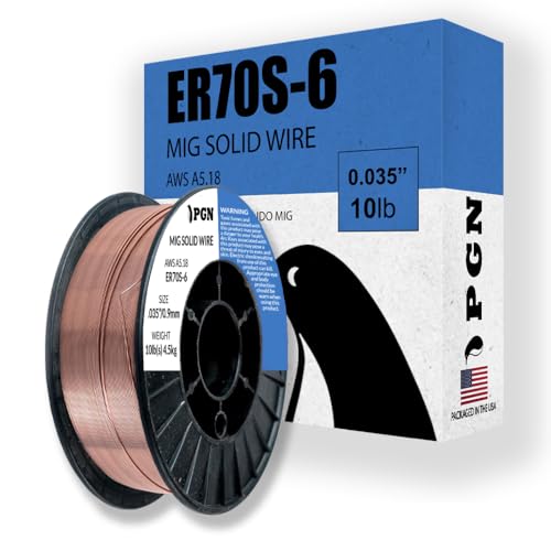
ER70S-6 PERFORMANCE: This .035 MIG welding wire supports precise arc control and low spatter for single-pass and multi-pass welding.
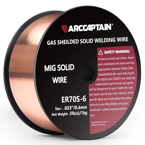
High-quality: ARCCAPTAIN's ER70S-6 mig welding wire .023" meets industry standards(Net Weight: 2lbs), ensuring consistent performance, superior strength. With its smooth feeding and stable welding parameters, you can achieve optimal penetration, high deposition rates, and exceptional overall welding performance.

Commonly used for general shop applications with poor fit-up.
How Shielding Gas Affects MIG Transfer Mode
Shielding gas has a direct effect on arc force, droplet size, penetration profile, oxidation, spatter, and the ability to reach spray transfer. The correct mixture depends on the base metal, wire, transfer mode, and qualified procedure.
| Material | Common Gas Direction | Transfer Notes |
|---|---|---|
| Carbon Steel | 100% CO2 or argon/CO2 blends for short circuit; argon-rich mixtures for conventional spray and pulse | Pure CO2 commonly produces short-circuit or globular behavior rather than conventional axial spray |
| Stainless Steel | Material-specific argon-rich blends with controlled CO2, oxygen, helium, or other components | Use the wire manufacturer’s recommendation to protect corrosion performance and arc stability |
| Aluminum | Usually 100% argon or an approved argon/helium blend | Spray and pulsed-spray transfer are common; do not use CO2 blends intended for carbon steel |
A 75% argon and 25% CO2 mixture is common for short-circuit carbon-steel welding, but it normally contains too much CO2 for conventional axial spray. Carbon-steel spray and pulsed-spray programs commonly require at least 80% argon, although the exact approved mixture comes from the machine, wire, and procedure documentation.
Gas flow rate also matters. Too little flow may allow air into the shielding zone. Excessive flow can create turbulence and draw surrounding air into the gas stream. Drafts, leaks, a clogged diffuser, a damaged nozzle, or excessive stickout can cause porosity even when the flowmeter appears correct.
Wire Size, Voltage, Wire Feed Speed, and Transition Current
On a typical constant-voltage GMAW setup, wire feed speed has a strong effect on welding current and deposition rate. Voltage mainly affects arc length and bead shape. The settings must remain balanced.
If wire feed speed is too high for the available voltage, the wire can stub into the pool. If voltage is too high for the feed rate, the arc can become long, harsh, and spattery. Increasing both settings can move the process from short circuit through globular transfer and, with suitable gas and current, into spray transfer.
Wire diameter affects current capacity and the spray transition point. A small wire generally reaches a useful current range at lower amperage than a larger wire. A larger wire can deposit more metal, but it needs adequate machine output, suitable gas, and enough material thickness to handle the heat.
Contact-tip-to-work distance also changes current and wire heating. Excessive stickout can reduce current, destabilize transfer, and increase spatter. Too little distance may overheat the contact tip or place the nozzle too close to the puddle. Use the machine and wire manufacturer’s recommendation for the selected mode.
Note: Do not copy a voltage and wire-feed setting from a different wire diameter, gas mixture, machine, or material and expect the same transfer. Start with the chart for your exact setup and make small test adjustments.
How to Identify the Transfer Mode
You can often identify the mode by combining sound, visible wire behavior, puddle fluidity, and spatter. Do not rely on sound alone, especially with modern waveform-controlled machines.
| Mode | What You May Observe |
|---|---|
| Short Circuit | Repeated wire contact, rhythmic crackling, small quickly freezing puddle, and moderate fine spatter |
| Globular | Large irregular droplets, harsh popping, unstable arc length, heavy spatter, and a difficult-to-control puddle |
| Spray | Fine axial droplets, steady humming or buzzing, fluid puddle, high deposition, and little spatter |
| Pulsed Spray | Rhythmic pulsing, controlled non-contact droplets, a more manageable puddle than conventional spray, and low spatter |
A high-speed camera provides the clearest transfer identification, but most welders use the combined clues above. When inspection or code classification matters, confirm the process and transfer mode through the approved procedure rather than making a casual visual guess.
WPS and Code Considerations
A welding procedure specification, or WPS, defines the allowed process variables for a qualified weld. It may control the process, transfer mode, wire classification, wire diameter, shielding gas, current, voltage, travel speed, position, joint design, and preheat.
Do not change from spray to short circuit, substitute a gas, or select a proprietary waveform on inspected work without confirming that the procedure allows it. Some codes and applications place special limits on short-circuit GMAW because incomplete fusion can be difficult to detect from surface appearance.
This article is educational guidance, not a replacement for an approved WPS, welder qualification, engineering review, owner’s manual, safety data sheet, or local code. Use qualified personnel for structural, pressure-containing, lifting, vehicle-safety, or life-safety welds.
Signs You Are Using the Wrong Transfer Mode
A weld can look attached while still having poor fusion or an unsuitable bead profile. Watch the arc, puddle, toes, root, sound, and spatter as you weld.
- Burn-through: Heat input is too high for the thickness, gap, or travel speed.
- Cold lap or overlap: The bead rolls onto the surface without fusing into the joint face.
- Heavy spatter: The voltage, feed rate, gas, stickout, polarity, consumables, or transfer region may be wrong.
- Ropey bead: The voltage, travel speed, work angle, or heat input may not match the joint.
- Undercut: Excessive voltage, poor angle, high current, or fast travel may wash metal away from the weld toe.
- Porosity: Gas loss, turbulence, leaks, drafts, moisture, rust, paint, oil, or mill scale may be contaminating the pool.
- Wire stubbing: Wire feed speed may be too high for the voltage, or the contact tip and feeding system may be restricting current transfer.
- Unstable arc: Check the work clamp, drive rolls, liner, contact tip, wire condition, gas coverage, and electrical connections.
Note: A smooth, attractive bead is not proof of a sound weld. When strength matters, verify joint preparation, penetration, fusion, weld size, procedure compliance, and inspection requirements.
Common Mistakes in MIG Welding Transfer Modes
One common mistake is choosing a mode only from material thickness. Thickness matters, but joint design, position, gas, wire, fit-up, and procedure requirements can change the correct choice. A short-circuit fillet on heavy steel may lack fusion, while conventional spray on thin sheet may burn through immediately.
Another mistake is trying to create spray transfer with a gas that cannot support it. Increasing voltage and wire feed speed while using an unsuitable carbon-steel gas blend may produce a hotter globular arc rather than a clean axial spray.
Improper wire-feed and voltage balance also causes problems. Too much feed for the voltage can make the wire stab into the pool. Too much voltage can create a long, harsh arc. In globular transfer, the wrong balance may create large droplets and severe spatter.
Inconsistent stickout is especially harmful during pulse welding because the waveform is developed for a defined electrical load and arc length. Large changes in torch distance can alter current, wire heating, and droplet detachment.
Finally, no transfer mode can overcome dirty metal, poor fit-up, a weak work-clamp connection, worn consumables, or failing gas delivery. Review these checks when a MIG welder is not working correctly before changing every machine setting.
Troubleshooting MIG Transfer Mode Problems
Troubleshoot in a consistent order. Confirm the wire, gas, polarity, work clamp, contact tip, liner, drive rolls, and clean base metal before making large parameter changes. Change one setting at a time and test on matching scrap.
| Problem | Likely Cause | What to Check |
|---|---|---|
| Excessive spatter | Globular region, wrong voltage, unsuitable gas, excessive stickout, or dirty metal | Confirm gas and mode, balance voltage with feed rate, shorten stickout, and clean the joint |
| Wire stubbing into the pool | Wire feed too high, voltage too low, or poor electrical contact | Balance wire feed and voltage, inspect the contact tip, drive rolls, liner, and work clamp |
| Porosity | Poor shielding, turbulence, leaks, drafts, moisture, or contaminated metal | Check gas flow, cylinder contents, hose, nozzle, diffuser, drafts, coatings, rust, oil, and moisture |
| Cold lap or incomplete fusion | Low heat, fast travel, long stickout, poor angle, or inadequate joint preparation | Use an approved hotter procedure, correct stickout and angle, prepare the joint, and inspect the root and toes |
| Burn-through | Too much heat, excessive gap, slow travel, or unsuitable transfer mode | Reduce heat within the approved range, improve fit-up, use short circuit or an approved pulse program, and increase travel as appropriate |
| Pulse arc still shorts or stubs | Wrong program, gas, trim, stickout, wire, or material selection | Confirm every program input and return trim or arc length to the manufacturer’s recommended starting point |
Safety Notes for MIG Transfer Mode Settings
Changing transfer modes can increase current, heat, arc radiation, molten-metal spray, noise, and fume generation. Conventional spray and pulsed spray may run hotter and brighter than low-end short circuit. Globular transfer can throw large amounts of spatter. Wear a welding helmet with the correct shade, safety glasses with side shields, flame-resistant clothing, dry insulated gloves, suitable footwear, and hearing protection where needed.
Place the work clamp on clean metal as close to the weld as practical. Inspect the machine, gun, cables, gas hose, regulator, and cylinder before use. Keep combustible materials away, protect nearby workers with screens, and keep appropriate fire-control equipment available.
Warning: Welding fumes and gases can cause serious harm. Use source-capture or local exhaust ventilation where possible, keep your head out of the plume, and do not weld in a confined space without the required ventilation, atmospheric controls, supervision, and rescue plan. When ventilation cannot control exposure, use respiratory protection selected under an appropriate safety program.
Remove paint, oil, plating, and other coatings from the weld area using a safe method. Galvanized, cadmium-plated, lead-coated, stainless, and unknown metals can produce hazardous fumes. Read the material safety data, consumable safety data sheet, and equipment instructions before welding. OSHA’s welding, cutting, and brazing requirements provide additional ventilation and protective guidance.
Never weld a closed tank, drum, pipe, wheel, or container that has held flammable or hazardous material unless it has been prepared under an approved procedure by qualified personnel. Transfer-mode knowledge does not make an unsafe workpiece safe.
Frequently Asked Questions
What is the difference between globular transfer and spray transfer?
Globular transfer uses large, irregular droplets and normally creates more spatter and a less stable arc. Spray transfer sends fine droplets axially across the arc, giving a smoother bead, higher deposition, and little spatter. Conventional spray also needs suitable argon-rich gas and enough current to exceed the transition point.
What are the four common modes of transfer in MIG welding?
The four commonly taught operating modes are short circuit, globular, spray, and pulsed spray. In formal AWS terminology, short-circuiting, globular, and spray are the main families, while pulsed spray is a subset of spray transfer.
Is globular transfer recommended for thick steel?
Globular transfer can occur on thicker carbon steel, especially with 100% CO2, but it is usually an unstable and spatter-heavy transition region rather than the preferred mode. Use stable spray, pulsed spray, or an approved short-circuit procedure when the equipment and job allow it.
What settings create globular transfer?
Globular transfer often appears when voltage and wire feed speed rise above stable short-circuit settings but the current, shielding gas, or other conditions do not support axial spray. No universal setting applies to every wire and machine. Start with the manufacturer’s chart and observe the actual droplet behavior.
What causes globular transfer?
Globular transfer occurs when large droplets form at the wire tip instead of repeated short circuits or a fine axial spray. Wire diameter, current, voltage, wire feed speed, shielding gas, stickout, and machine characteristics all influence it. Pure CO2 commonly promotes globular behavior above the short-circuit range on carbon steel.
Which MIG transfer mode has the least spatter?
Stable spray and pulsed-spray transfer usually create the least spatter when the wire, gas, stickout, machine program, and settings are correct. Pulsed spray is especially useful when you want low spatter with lower average heat and improved puddle control.
Can you use spray transfer on thin metal?
Conventional spray is usually too hot for thin sheet and can cause burn-through or distortion. Short circuit is normally the safer starting mode. Pulsed spray may work on thinner material than conventional spray, but it still needs an approved machine program, gas, wire, joint, and procedure.
Can 75/25 argon and CO2 produce spray transfer?
A 75% argon and 25% CO2 blend is widely used for short-circuit carbon-steel welding, but it normally contains too much CO2 for conventional axial spray. Carbon-steel spray and pulsed-spray programs commonly call for at least 80% argon, subject to the wire and machine documentation.
Does selecting pulse on the welder guarantee pulsed-spray transfer?
No. The selected waveform and the actual transfer at the arc are not always identical. An incorrect program, gas, wire, stickout, trim, or parameter range may still cause shorting or unstable transfer. Confirm the program inputs and observe the arc behavior.
Sources
- Miller Guidelines for Gas Metal Arc Welding — transfer-mode behavior, gas selection, setup variables, troubleshooting, and safety.
- American Welding Society Transfer Mode Clarification — formal transfer families and the distinction between selected waveform and observed transfer.
- Miller Guide to Pulsed MIG Welding — peak and background current, gas requirements, heat control, and pulse technique.
- ESAB MIG Welding Guide — short-circuit, globular, spray, and pulsed-transfer characteristics.
- OSHA 29 CFR 1910.252 — welding ventilation, fume, fire, and protective requirements.
- AWS Free Welding Safety Resources — access to ANSI Z49.1 and welding safety fact sheets.
Conclusion
The right MIG transfer mode depends on more than material thickness. Short circuit gives you lower heat and fast puddle freezing for thin or positional work. Conventional spray provides smooth, high-deposition welding on suitable thicker joints. Pulsed spray adds controlled droplet transfer and lower average heat. Globular transfer is important to recognize, but it is usually a transition region to correct rather than a preferred setting.
Before welding the final part, match the wire, shielding gas, machine program, joint, position, and procedure. Test on matching scrap, keep a stable stickout, watch the puddle edges, listen to the arc, and inspect for fusion instead of judging strength by bead appearance alone. For critical work, follow a qualified WPS and the applicable safety and inspection requirements.




