
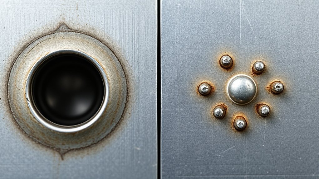
Plug welds and resistance spot welds can both join overlapping sheet metal, but they do it in different ways and are not automatically interchangeable. The right choice depends on the joint design, material, access, equipment, required finish, and—on a vehicle—the exact body repair procedure. Use this guide to compare the methods, avoid common defects, and verify weld quality before working on a finished part.
Quick Answer
A plug weld uses an arc-welding process and filler wire through a hole in the top sheet. A spot weld uses electrode force and electrical resistance to fuse overlapping sheets without filler metal. Neither is always stronger; use the method, weld size, count, spacing, and settings required by the drawing, welding procedure, or vehicle manufacturer.
Key Takeaways
- Plug welding is useful when only one side of a lap joint is accessible and the approved procedure permits an arc-welded replacement for a spot weld.
- Resistance spot welding is fast, repeatable, filler-free, and often best for duplicating factory sheet-metal joints when both sides are accessible.
- Hole diameter, weld spacing, current, time, force, wire, primer, adhesive, and corrosion protection are procedure-specific—not universal rules.
- Test welds on matching coupons and perform the required destructive test before welding a structural or automotive part.
At a Glance
| Time Required | Varies by joint and repair; include setup, test coupons, destructive testing, welding, dressing, and corrosion protection. |
| Difficulty | Intermediate for noncritical mild-steel practice; advanced or professional for structural and late-model vehicle repairs. |
| Tools Needed | GMAW/MAG welder and punch or drill for plug welds, or a squeeze-type resistance spot welder; plus matching test coupons, clamps, cleaning tools, PPE, and ventilation. |
| Cost | Varies widely. Plug welding can use suitable GMAW equipment; spot welding requires dedicated resistance equipment. Cost must never override the specified repair method. |
Warning: Structural vehicle welding is not a trial-and-error repair. Identify the steel or aluminum grade, obtain the current model-specific procedure, disable vehicle systems as directed, make test welds, and use only the approved attachment method. Incorrect heat input or weld placement can reduce crash protection.
What Are Plug Welds and How Do They Work?
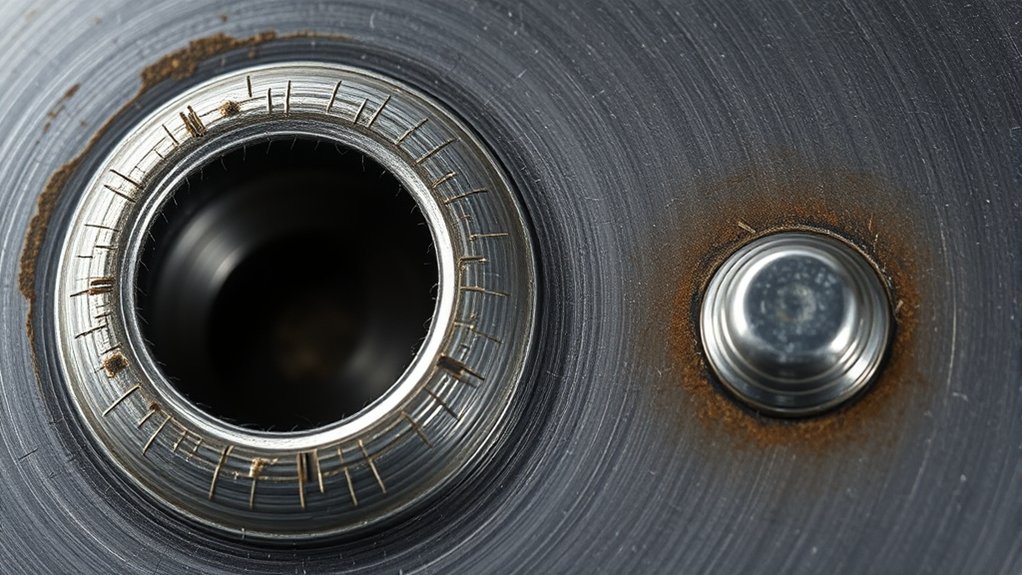
A plug weld joins overlapping members through a round hole in the outer or top member. In sheet-metal repair, a GMAW or MAG gun directs the arc through that hole so the lower sheet melts and the filler wire fuses the two pieces together. The completed weld fills the opening and may be dressed flush only when the procedure allows it.
Do not treat one hole size or spacing rule as universal. The correct diameter, weld count, spacing, edge distance, wire, shielding gas, and settings come from the engineering drawing, welding procedure specification, equipment manufacturer, or vehicle body repair manual. For example, General Motors repair guidance cited by I-CAR permits 8 mm GMAW/MAG plug welds in certain locations when squeeze-type resistance spot welding cannot be used; that example is not a rule for every vehicle or fabrication job.
Plug welding is especially useful when the joint is designed as a lap joint, the lower sheet is accessible to the arc through the hole, and resistance-welder arms cannot reach both sides. Good fit-up is critical: a gap between the sheets can increase heat, reduce fusion at the interface, and make burn-through more likely.
How Does the Spot Welding Process Work?
Resistance spot welding clamps overlapping conductive sheets between electrodes. Mechanical force holds the sheets together while a high electrical current passes through the joint. Resistance at the sheet interface generates heat and forms a fused weld nugget without filler wire. The electrodes remain clamped during the hold portion of the cycle so the nugget can solidify under pressure.
The American Welding Society identifies current, weld time, electrode force, material properties, setup, monitoring, and maintenance as key resistance-welding variables. Modern squeeze-type resistance spot welders may select settings automatically, but some materials and vehicle procedures require manual parameters, specific tip shapes, or destructive testing.
Spot welding usually requires access to both sides of the flange. The arms and electrodes must reach the joint, sit square to the surface, and apply the required force. Worn tips, poor alignment, coatings, excessive panel gaps, current shunting, or incorrect settings can produce a weak weld even when the surface dimple looks acceptable.
Comparing Plug Welds and Spot Welds: Key Differences
| Factor | Plug Weld | Resistance Spot Weld |
|---|---|---|
| Heat source | Electric arc melts base metal and filler wire. | Electrical resistance heats the sheet interface while electrodes apply force. |
| Filler metal | Yes, for GMAW/MAG plug welding. | No. |
| Access | Usually performed from one side after making a hole in the top sheet. | Normally needs electrode access to both sides. |
| Preparation | Hole preparation, tight clamping, clean weld zone, and procedure-specific coating treatment. | Clean, aligned flanges plus correct tips, arms, force, current, time, and any specified adhesive or primer. |
| Speed | Slower because holes, arc welding, cooling, and dressing may be required. | Fast once equipment and weld schedules are set. |
| Heat-affected area | Often larger because an arc and filler metal are used. | Usually localized because the weld cycle is short and concentrated. |
| Finish | May leave a raised fill that needs careful dressing. | Leaves electrode impressions and often needs little finishing. |
| Typical advantage | Works where two-sided resistance-welder access is unavailable and the procedure permits it. | Repeatable, filler-free joining that can closely duplicate many factory seams. |
| Primary rule | Use the specified method and validate it with the required test—not a blanket assumption about which weld is stronger. | |
Note: Weld strength depends on the material stack, thickness, joint geometry, nugget or fusion size, weld count, spacing, heat input, fit-up, and workmanship. A larger-looking weld is not automatically a better weld.
Products Worth Considering

Two types of Trigger Flexibility & Safety: The maximum current is 1,380 A, and the power is 11.5 KW. Seamlessly switch between hands-free foot pedal operation and precise hand control (Trigger) for versatile workflows and enhanced safety when handling sensitive batteries.

5 Minute Quick Start Spot Welder: We use a wide voltage input of 100-240V and an adapter of 15amp high current for fast charging Connect the spot welding machine to the power supply using our adapter, and quickly reach the spot welding mark within 5 minutes (the display screen shows OK for spot welding), which can be used anywhere in the world

Powerful 1650A Output & 10.2kW Max Power – Delivers consistent, strong welds for cylindrical power batteries, phone batteries, and Button batteries, supporting nickel, pure nickel, and steel up to 0.3mm thickness.
Why Plug Welding Is Great for Structure

Plug welding can create a sound load-carrying connection when the joint is engineered for it and the weld fully fuses to the lower sheet around the hole. It is useful for selected structural repairs, backing-strip joints, flanges, and panel replacements where the approved procedure calls for a plug weld or allows one because spot-welder access is blocked.
Enhanced Strength and Integrity
A quality plug weld needs complete fusion at the interface—not merely a filled hole. The arc should establish a molten pool on the lower sheet and then fuse into the edge of the opening without excessive heat. Strength must be confirmed with the specified coupon test, weld size, count, and spacing.
Do not use a formula such as “set power to 1.5 times the sheet thickness.” Welder controls do not share one universal scale, and material grade, coating, wire, gas, joint stack, position, and machine characteristics all affect the correct setting. Start with the approved procedure or equipment data, then qualify the setup on matching coupons.
Versatile Application in Repairs
Plug welds are practical for attaching patch panels and replacement flanges when the back side cannot accept a spot-welder electrode. They can also reproduce a specified series of discrete attachment points without running a continuous seam that would add unnecessary heat and distortion.
In automotive work, plug welding is not automatically the preferred structural method. I-CAR reports that General Motors requires squeeze-type resistance spot welding where it is accessible and directed by the repair procedure. Other manufacturers may specify plug welds, spot welds, weld bonding, rivets, brazing, or a combination. Follow the current model-specific instructions.
Plug Weld Limitations
- More preparation: The top sheet must be punched or drilled without damaging the lower sheet, and the panels must fit tightly.
- More heat: Arc welding may create a larger heat-affected zone and more distortion than a properly set resistance spot weld.
- More finishing: Raised weld metal may need dressing, but grinding below the base-metal surface weakens the panel.
- Greater risk of porosity or burn-through: Coatings, contamination, excess gap, and poor settings can cause defects.
- Procedure limits: Some high-strength or ultra-high-strength materials prohibit this process except at named locations.
Spot Welding Benefits for Aesthetics
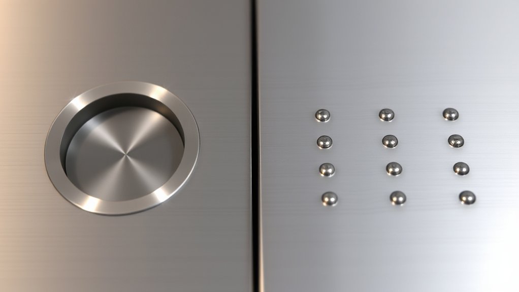
Spot welding can produce a clean, factory-like appearance, but its value goes beyond aesthetics. The process is fast, uses no filler wire, concentrates heat at the interface, and can make repeatable welds when the equipment is calibrated and maintained.
- Factory-style attachment: Correct electrode impressions can closely match many original sheet-metal seams.
- Minimal added weld metal: There is usually less grinding and a lower risk of thinning the panel during cleanup.
- Short weld cycle: Concentrated heat can reduce distortion compared with a slower arc-welding process.
- Process control: Suitable equipment can monitor or adjust current, time, and force for the material stack.
A recessed dimple is only a surface clue. It does not prove that the hidden nugget is large enough or fully fused. Visual inspection must be backed by the required test welds and destructive testing.
Spot Weld Limitations
- The electrodes normally need access to both sides of the joint.
- Arms, tips, cooling, electrical supply, and calibration must match the job.
- Tip wear, poor alignment, panel gaps, coatings, or current shunting can reduce nugget size.
- Some joints are too thick, too complex, or made from material combinations that need another approved process.
When to Use Plug Welding Instead of Spot Welding
Use plug welding instead of spot welding only when the design or repair procedure calls for it, or when an approved procedure allows it because resistance-welder access is not possible. The deciding factors are access, material, stack thickness, required attachment method, equipment capability, and verified weld quality.
Strength and Durability
Choose the weld that delivers the required joint performance—not the process with the larger visible footprint. A properly designed plug weld can carry substantial shear load, while a properly made spot-weld pattern can be structural, repeatable, and fatigue-resistant. Both can fail if the weld size, count, spacing, settings, fit-up, or material restrictions are wrong.
Equipment Accessibility Considerations
Plug welding has a clear access advantage because the gun works from the hole side of the joint. It is often practical inside wheel openings, boxed flanges, rocker areas, and other locations where spot-welder arms cannot reach or sit square to both surfaces. Before substituting it, confirm that the procedure permits the change and states the required hole size and weld pattern.
Automotive OEM and Material Restrictions
Late-model vehicles may combine mild steel, high-strength steel, ultra-high-strength steel, aluminum, adhesives, sealers, and layered reinforcements in one repair area. Heat that is acceptable on one panel may be prohibited on the next. American Honda’s September 2025 welding guidance, for example, limits some welding methods by steel tensile strength and allows MAG plug welding on 1,500 MPa hot-stamped steel only at locations named in the model-specific manual. It also states that welding instructions must be followed exactly to obtain adequate strength.
Before welding a vehicle, verify the VIN, model year, body construction, material strength, attachment method, weld count, weld locations, wire strength, shielding gas, adhesive, primer, and corrosion-protection steps in the current OEM information. Do not infer the procedure from a similar model.
Top Automotive Repair Applications for Plug Welds
Common automotive uses include the following, but each one still requires vehicle-specific approval:
- Patch and outer-panel flanges: Plug welds can secure a replacement panel where the top flange can be punched and the lower panel remains intact.
- Factory seam replacement with limited access: Some procedures allow plug welds to replace selected original spot welds when STRSW arms cannot reach.
- Backing-strip or insert joints: A plug weld may attach a specified insert before completing the rest of a sectioning joint.
- Multi-layer joints: Only when the procedure provides the approved weld diameter, number, location, and material limits.
After welding, restore every disturbed corrosion-protection layer. The weld itself does not seal the full lap joint or prevent moisture from entering the flange.
Products Worth Considering

Designed to aide and speed up the welding of holes in steel body panels
Our automotive electrical disconnect pliers are made from high-carbon steel that is sturdy durable and not easy to rust or damage. The robust build ensures that couplers can be disconnected without causing wear to the tool itself. And the handle is made by plastic coated that is anti slip, comfortable and labor-saving.

CTA Tools 3238 Spark Plug Gap Gauge - 9-Wire is designed to accurately measure spark plug gaps. The sizes range from 0.025, 0.030, 0.035, 0.040, 0.044, 0.045, .0.050, 0.055 and 0.060-inches. Heavy-duty construction allows for strength and durability. California Prop 65 - Warning, This product contains chemicals known to the State of California to cause cancer, birth defects or other reproductive harm.
Situations Where Spot Welding Shines
Resistance spot welding is often the better choice when:
- Both sides of the flange are accessible to the correct electrodes.
- The original joint was spot welded and the repair procedure requires or prefers STRSW.
- Many consistent welds must be made quickly along a flange.
- Low added weld metal and minimal dressing are important.
- The equipment can supply the required current and force for the material stack.
- Weld bonding or another procedure-specific combination is required.
Production speed is an advantage only after the machine, electrodes, surfaces, and test welds are correct. A rapid series of weak welds is not an acceptable repair.
Best Practices for Achieving Quality Welds
The finished part is not the place to discover that the settings were wrong. Qualify the weld on matching coupons first.
How to Make a GMAW Plug Weld
- Verify the procedure. Confirm that plug welding is allowed and identify the material, stack thickness, hole diameter, weld count, spacing, wire, gas, and corrosion-protection requirements.
- Prepare matching coupons. Use the same material type, coating, thickness, number of layers, orientation, and weld position as the real joint.
- Make the holes correctly. Punch or drill only the top sheet to the specified diameter. Deburr it without enlarging or thinning the edge.
- Prepare and clamp the joint. Clean only the areas required by the procedure, keep the mating surfaces tight, and position the work clamp where it provides a stable circuit.
- Set and test the welder. Use the approved starting parameters, make a test weld, inspect it, and perform the specified destructive test. Adjust only within the procedure and equipment guidance.
- Fuse to the lower sheet. Direct the arc at the exposed lower sheet, establish fusion, and fill outward into the edge of the hole. Avoid excessive buildup, porosity, undercut, and burn-through.
- Control heat and sequence. Allow cooling between nearby welds and follow the stated sequence to limit distortion and heat accumulation.
- Inspect, dress, and protect. Confirm fusion and weld size using the required method. Dress flush only where permitted, then restore primer, seam sealer, cavity wax, and other coatings.
Pro Tip: Keep the failed and passed coupon pieces beside the welder during the job. They provide a direct reference for fusion, tear-out behavior, heat level, and grinding limits.
How to Make a Resistance Spot Weld
- Confirm the approved weld schedule. Identify the material stack, coating, weld count, location, tip shape, and any required manual settings.
- Prepare matching test coupons. Duplicate the number of layers, material types, thicknesses, coatings, adhesive or primer, and access conditions.
- Inspect the equipment. Check tip condition and alignment, arm contact points, cooling system, cables, and machine calibration.
- Prepare the flange. Remove or retain coatings only as directed. Clamp the panels tightly and keep the electrode faces square to the joint.
- Make and test sample welds. Use automatic or manual settings as required, then visually inspect and destructively test the coupons before welding the part.
- Follow the weld pattern. Place the welds at the specified locations and spacing. Avoid welding directly over an old nugget unless the procedure says to do so.
- Watch for process changes. Stop if the machine cannot calibrate, tips overheat, indentation changes, expulsion occurs, or weld quality becomes inconsistent.
- Complete corrosion protection. Apply the specified primer, seam sealer, adhesive, and cavity protection after the welds pass inspection.
Common Defects and Troubleshooting
| Problem | Likely Causes | Correction |
|---|---|---|
| Plug weld lacks fusion | Arc stayed on the hole edge, settings too cold, poor grounding, contamination, or panel gap. | Reprepare coupons, improve fit and circuit, direct the arc to the lower sheet, and retest approved settings. |
| Porosity | Paint, primer, oil, rust, moisture, poor gas coverage, or excessive stickout. | Follow the coating-preparation rule, correct gas flow and gun setup, and repeat the coupon test. |
| Burn-through or excessive tear-out | Too much heat, oversized hole, panel gap, slow technique, or wrong material setting. | Correct the fit and hole, reduce heat within approved limits, and requalify on coupons. |
| Small or weak spot-weld nugget | Insufficient current, time, or force; oversized or worn tips; poor contact; coating; or shunting. | Service and align the tips, confirm the material stack and settings, eliminate gaps or current bypass, and destructively retest. |
| Excessive indentation or expulsion | Excessive current or time, incorrect force, poor fit, contaminated surfaces, or damaged tips. | Stop welding, inspect equipment and fit-up, restore the approved schedule, and make new test welds. |
| Panel distortion | Too much total heat, poor sequence, inadequate clamping, or overgrinding. | Use the specified sequence, allow cooling, improve clamping, and limit dressing to the weld buildup. |
Welding Safety and Corrosion Protection
Welding hazards include fumes, ultraviolet radiation, burns, eye injury, electric shock, fire, and mechanical pinch or crush hazards. OSHA recommends controlling these risks with proper work practices, ventilation, and personal protective equipment. Keep combustibles away, provide fire protection as required, and never weld on a container, fuel system, or unknown coated surface until it has been made safe under an approved procedure.
Warning: Welding galvanized or coated steel can release hazardous fumes. Use source capture or suitable ventilation, approved respiratory protection when required, and the correct coating-removal procedure. On vehicles, follow OEM steps for the battery, supplemental restraint system, fuel system, electronics, and high-voltage disablement before hot work.
Galvanized and Coated Steel
Remove coatings only where the approved procedure requires bare metal. Do not assume weld-through primer belongs under every plug weld. American Honda’s September 2025 guidance says zinc-rich weld-through primer is used on specified bare mating surfaces for STRSW, but it should not be used for MAG plug welding, MAG butt welding, or MIG brazing because it can harm joint quality. Other manufacturers may give different instructions.
Post-Weld Corrosion Protection
After the weld passes inspection, restore the full corrosion-protection system named in the procedure. That may include epoxy primer on exposed steel, seam sealer at the flange, adhesive, undercoating, and cavity wax on the back side. A sound weld can still develop corrosion if bare metal, burned coating, or an open lap seam is left untreated.
Frequently Asked Questions
What is the difference between a plug weld and a spot weld?
A plug weld uses an arc and filler wire through a hole in the top sheet to fuse it to the lower sheet. A resistance spot weld clamps the sheets between electrodes and uses current, resistance heat, and force to form a nugget without filler metal.
Which is stronger: a plug weld or a spot weld?
Neither process is always stronger. Joint strength depends on material, thickness, joint design, weld size, count, spacing, heat input, fit-up, and quality. For structural or automotive work, use the specified process and confirm it with the required test.
What are the disadvantages of plug welds?
Plug welds require holes, close panel fit, more arc heat, filler wire, and often more finishing. They are also vulnerable to lack of fusion, porosity, burn-through, and excessive grinding. Some high-strength materials or repair locations prohibit them.
When should you use a plug weld?
Use a plug weld when the joint is designed for it or an approved repair procedure permits it, especially when only one side is accessible and spot-welder arms cannot reach. Do not substitute it for a factory spot weld without authorization.
What size hole should be used for a plug weld?
Use the diameter specified by the drawing, welding procedure, training standard, or vehicle manufacturer. There is no universal hole size. Material thickness, number of layers, steel grade, joint design, and required weld nugget all affect the requirement.
What are the common problems with spot welders?
Common problems include worn or oversized tips, poor tip alignment, inadequate cooling, incorrect current, time or force, panel gaps, coating interference, shunting, excessive indentation, expulsion, and failed calibration. Stop and retest whenever weld quality changes.
How can you tell whether a plug weld or spot weld is good?
Start with visual inspection, but do not rely on appearance alone. Make test welds on matching coupons and use the destructive test, nugget measurement, tear-out requirement, or other acceptance method specified for the job. I-CAR explains that destructive testing lets the technician correct settings before welding the vehicle.
Conclusion
Plug welding and resistance spot welding are different tools for different joint conditions. Plug welding offers one-sided access and can replace selected attachment points when the procedure permits it. Spot welding is fast, filler-free, and often the required or preferred way to reproduce factory sheet-metal joints. The safest decision is to follow the governing procedure, qualify the setup on matching coupons, inspect the completed welds, and restore every corrosion-protection layer.
Sources
- American Welding Society — Certified Resistance Welding Technician — resistance-welding fundamentals, process variables, setup, quality control, and maintenance.
- OSHA — Welding, Cutting, and Brazing Hazards and Solutions — welding fumes, radiation, burns, electrical hazards, and PPE.
- I-CAR — General Motors: Spot Weld Replacement — OEM repair procedures, weld count, location, and STRSW requirements.
- I-CAR — Steel Spot and Plug Weld Nugget Size: GM — an OEM-specific example of 8 mm plug welds where STRSW access is unavailable.
- American Honda — Body Repair Manual Welding and Sectioning Guideline Revisions — approved welding methods, material limits, wire selection, and weld-through primer guidance.
- I-CAR — Back-to-Basics: Destructive Weld Testing — matching coupons, visual checks, and destructive testing before vehicle welding.




