
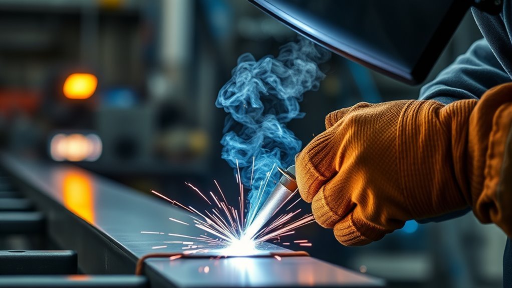
Synergic MIG welding helps you set up a MIG weld faster by linking related welding variables through a built-in program. Depending on the machine, you may select the wire, shielding gas, material, thickness, wire feed speed, or amperage, then fine-tune the arc. The result is a faster starting point that is easier to repeat across supported jobs.
Quick Answer
Synergic MIG welding uses a programmed relationship to coordinate wire feed speed, voltage, and sometimes pulse or arc-response settings. You choose the correct program and one main power setting, then adjust trim if needed. It speeds up setup, but it does not replace clean metal, sound technique, test welds, or inspection.
Key Takeaways
- Synergic MIG links related welding variables through a program developed for a specific wire, gas, material, and process range.
- The main control may be thickness, amperage, or wire feed speed, depending on the welder.
- Standard synergic MIG, synergic pulsed MIG, and double-pulse MIG are different operating options.
- Trim, arc length, inductance, or dynamics may still need small adjustments after a test bead.
- A preset never replaces correct polarity, clean metal, gas coverage, PPE, ventilation, fit-up, or an approved welding procedure.
At a Glance
| Time Required | About 5 to 15 minutes once the wire, gas, gun, and workpiece are ready |
| Difficulty | Beginner to intermediate for basic work; advanced for coded, structural, pressure, or safety-critical welds |
| Tools Needed | Synergic MIG welder, compatible gun and wire-feed parts, approved wire, shielding gas, work clamp, PPE, cleaning tools, and matching scrap test coupons |
| Cost | No extra consumable is required only because the mode is synergic; machine price, software options, guns, and accessories vary |
Warning: Synergic settings do not make welding risk-free. Wear suitable eye, face, hand, hearing, foot, and skin protection. Control fumes at the source, keep combustibles away, secure gas cylinders, and follow the welder and consumable manuals. Confined-space welding requires specific atmospheric, ventilation, entry, and rescue controls.
What Is Synergic MIG Welding?
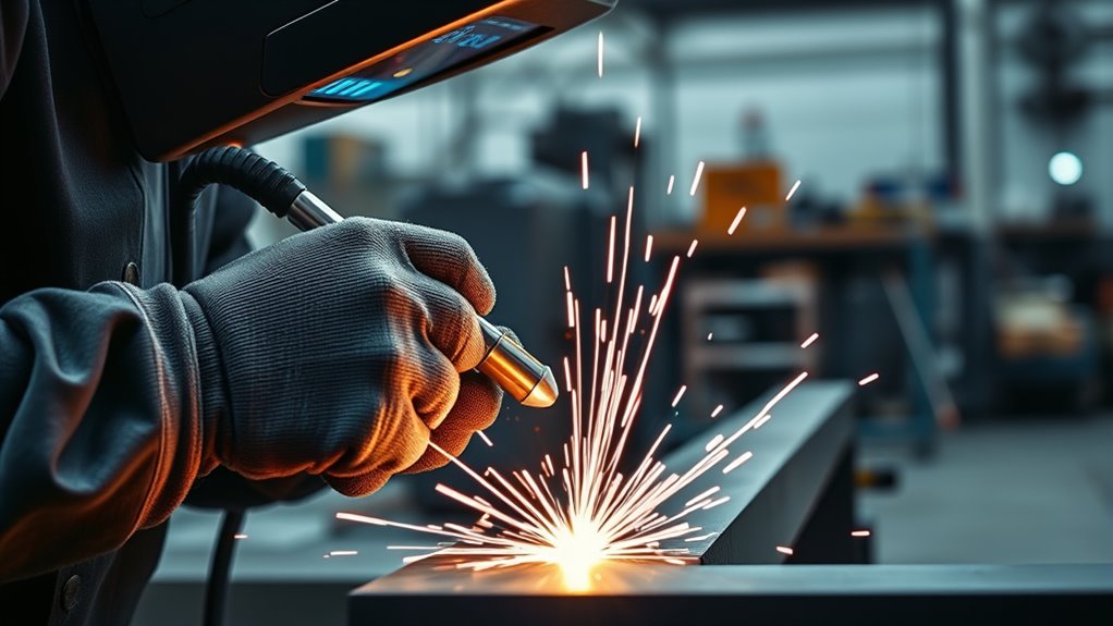
Synergic MIG welding is a form of gas metal arc welding, or GMAW, in which the power source coordinates related settings through a stored program. The program is often called a synergic line, characteristic, schedule, or curve.
The exact controls vary by manufacturer. Some welders ask you to select the material, wire diameter, shielding gas, and material thickness. Others ask you to select the wire and gas program, then use wire feed speed or amperage as the main power control. When that main setting changes, the machine adjusts voltage and other variables according to the selected program.
For example, an official Lincoln Electric synergic-welder manual describes a mode in which the operator sets wire feed speed and the machine changes the matching voltage. A Fronius synergic setup uses selected filler metal, wire diameter, shielding gas, and a welding-power parameter.
The stored relationship is developed for a specific combination of wire, gas, material, transfer mode, and machine design. It is not a universal setting that works with every consumable. Selecting a steel program while using aluminum wire, the wrong gas, or a different wire diameter can produce an unstable arc or an unacceptable weld.
Synergic MIG does not weld for you. It brings the machine close to a usable range, but the welder must confirm the program, technique, bead profile, fusion, and final acceptance.
Synergic control is useful when you are learning, making repeat parts, training several operators, or moving between supported material thicknesses. You still need correct polarity, clean consumables, good electrical connections, steady wire feeding, proper gas coverage, and a suitable travel speed.
Note: “Synergic,” “Auto-Set,” “Smart MIG,” and similar terms are not guaranteed to mean the same thing. Read the machine manual to learn which inputs are automatic, which remain manual, and which programs are installed.
How Synergic MIG Welding Simplifies Setup
Synergic MIG welding reduces the number of independent settings you must balance. On a basic manual MIG welder, wire feed speed and voltage are separate. If one changes, you normally adjust the other until the arc becomes stable again.
In synergic mode, the machine already has a programmed relationship between those variables. You choose the correct process information, set the requested power value, and make a test weld. The welder then keeps the linked settings near the programmed relationship as you move through the supported range.
Depending on the machine, your selections may include:
- Base material: mild steel, stainless steel, aluminum, silicon bronze, or another supported alloy.
- Filler wire: the wire classification or program family supported by the machine.
- Wire diameter: the actual diameter installed in the feeder and contact tip.
- Shielding gas: the exact gas or gas family listed for that program.
- Main power setting: thickness, amperage, deposition rate, or wire feed speed.
- Transfer mode: standard MIG, pulse, double pulse, or another supported process.
- Fine adjustment: trim, arc length, voltage correction, inductance, or arc dynamics.
Once those inputs are correct, the machine supplies a starting combination for wire feed speed, voltage, and arc response. You then inspect the test weld and make a small correction if the arc is harsh, the bead is too tall, the toes do not blend into the base metal, or the puddle is too fluid.
Pro Tip: Use scrap from the same material, thickness, joint preparation, and position as the real part. A flat bead on thick scrap does not prove that the same setting will work on a vertical joint, a wide gap, or thin sheet.
How to Set Up a Synergic MIG Welder
Use this general setup flow when your machine has a synergic MIG mode. Button names and menu order vary, so keep the machine manual nearby.
- Identify the job requirements. Confirm the base metal, thickness, joint type, welding position, required filler metal, and any drawing, welding procedure specification, code, or OEM repair instruction.
- Check machine capacity. Confirm that the welder, gun, input circuit, duty cycle, and installed software support the required wire and process.
- Install the correct wire-feed parts. Match the drive rolls, liner, guides, gun, and contact tip to the wire type and diameter. Aluminum generally needs equipment designed to feed soft wire without shaving or bird-nesting.
- Load clean, dry wire. Keep the wire free of rust, oil, moisture, and shop dust. Set drive-roll tension only high enough to feed the wire steadily.
- Connect the specified shielding gas. Use the gas required by the wire data sheet, machine program, and welding procedure. Inspect the hose, regulator, diffuser, O-rings, and nozzle for leaks or blockage.
- Set the required polarity. Solid GMAW wire commonly uses DCEP. Flux-cored wire polarity varies, so follow the wire label, data sheet, and machine manual instead of guessing.
- Attach the work clamp to clean metal. Place it where the electrical path is sound and will not pass through bearings, electronic modules, hinges, or other parts that could be damaged.
- Select the exact synergic program. Match the material, wire classification, wire diameter, shielding gas, gun type, and transfer mode. Do not select a program only because its thickness display looks close.
- Set the main welding-power value. Enter the thickness, amperage, or wire feed speed requested by the machine.
- Leave trim and dynamics at their defaults. Begin at the programmed center or nominal value unless a qualified procedure says otherwise.
- Set gas flow under flowing conditions. Pull the trigger or use the gas-purge function while reading the flowmeter. Excessive flow can create turbulence and draw air into the shielding envelope.
- Make a test bead. Use matching scrap and reproduce the real joint, position, stickout, torch angle, and travel speed as closely as possible.
- Inspect and adjust one item at a time. Check gas coverage, feeding, fit-up, bead shape, fusion, penetration evidence, undercut, overlap, porosity, spatter, and distortion before changing trim.
- Record the proven setup. Save the job in the welder when possible and note the program, wire, gas, trim, joint, position, stickout, and travel method.
This process is faster than building every parameter from scratch, but it remains a setup procedure rather than a weld-quality guarantee. For critical work, the test and inspection requirements come from the applicable procedure, drawing, code, contract, or OEM instruction.
Synergic MIG, Pulsed MIG, and Double-Pulse MIG
Synergic control and pulsed welding are related but different ideas. Synergic control links settings. Pulsed MIG controls current in a repeating waveform to manage droplet transfer and heat input. A machine can therefore offer standard synergic MIG, synergic pulsed MIG, or both.
| Mode | What the Machine Does | Common Uses |
|---|---|---|
| Standard synergic MIG | Links voltage and other arc settings to the main power control for a standard GMAW program. | General steel fabrication, sheet metal, repair work, and repeat production within the program range. |
| Synergic pulsed MIG | Coordinates pulse current, background current, timing, wire feed speed, and arc length through a material-specific program. | Aluminum, stainless steel, controlled spray transfer, lower-spatter production, and applications needing better heat control. |
| Double pulse or pulse-on-pulse | Adds a slower modulation over the pulsed arc, changing heat and deposition in a repeating pattern. | Visible aluminum or stainless welds, heat-sensitive parts, and stacked-dime-style bead appearance where the procedure allows it. |
Not every machine supports all three modes, and the same program may not be available with every gun. Check whether the desired process works with the standard gun, spool gun, or push-pull system before buying accessories.
Products Worth Considering

7 in 1 Welding Machine: The multi-function welding machine included Gas/Solid Wire MIG,Pulse MIG, Gasless Flux Core MIG, Stick/MMA, Spot welding, Lift TIG, spool gun compatible (tig gun and spool gun not included,WP-17V-35,LBT150).

5-in-1 MIG Welder: This 250A 5-in-1 pro mig welder supports various functions - MIG Pluse, gasless MIG, gas MIG, MMA, and Lift TIG. The innovative pulse welding function provides fast, high-quality, low-spatter welds and better thermal control than traditional MIG welders, allowing perfect welds at lower temperatures.

6-IN-1 Aluminium MIG Welder: Experience true multi-process flexibility. The MIG/Pulsed MIG/Flux Core/Spool Gun MIG/Lift TIG/Stick welder delivers professional-grade performance across the board. Compatible with spool gun and Lift TIG torch (both sold separately) for specialized applications, this powerhouse handles everything from thin-gauge aluminum to thick structural steel with ease.
Synergic MIG vs. Non-Synergic MIG
Compared with non-synergic MIG, synergic MIG automates the relationship between major welding parameters. When you adjust the main power control, the machine changes related variables according to the selected program.
With non-synergic MIG, you set wire feed speed and voltage independently. That gives you direct control, but it also requires a stronger understanding of arc length, wire burn-off, transfer mode, heat input, travel speed, and bead response.
| Feature | Synergic MIG | Non-Synergic MIG |
|---|---|---|
| Setup style | Choose a matching program and main power setting, then fine-tune. | Set wire feed speed and voltage independently. |
| Best for | Repeat work, frequent changeovers, training, pulse programs, and multi-operator shops. | Simple equipment, unusual parameter combinations, and operators who prefer independent controls. |
| Learning curve | Easier starting point, but correct program selection still takes knowledge. | More trial and error, but it clearly teaches how voltage and wire feed interact. |
| Fine control | Usually adjusted with trim, arc length, dynamics, or advanced-menu controls. | Voltage and wire feed can be changed directly and independently. |
| Main limitation | Performance depends on choosing a program that truly matches the wire, gas, material, and gun. | Performance depends heavily on the operator’s setup skill. |
If you want speed and repeatability, synergic MIG gives you a clearer path to a starting setting. If you need an unusual parameter combination or use a basic welder, manual MIG can still produce excellent results when the setup is correct.
For some outdoor work, self-shielded flux-cored welding can tolerate wind better than gas-shielded MIG because it does not depend on an external gas envelope. Gas-shielded flux-cored wire still needs draft control, and every flux-cored wire must be used with the polarity and settings listed by its manufacturer.
Key Features That Improve Weld Quality
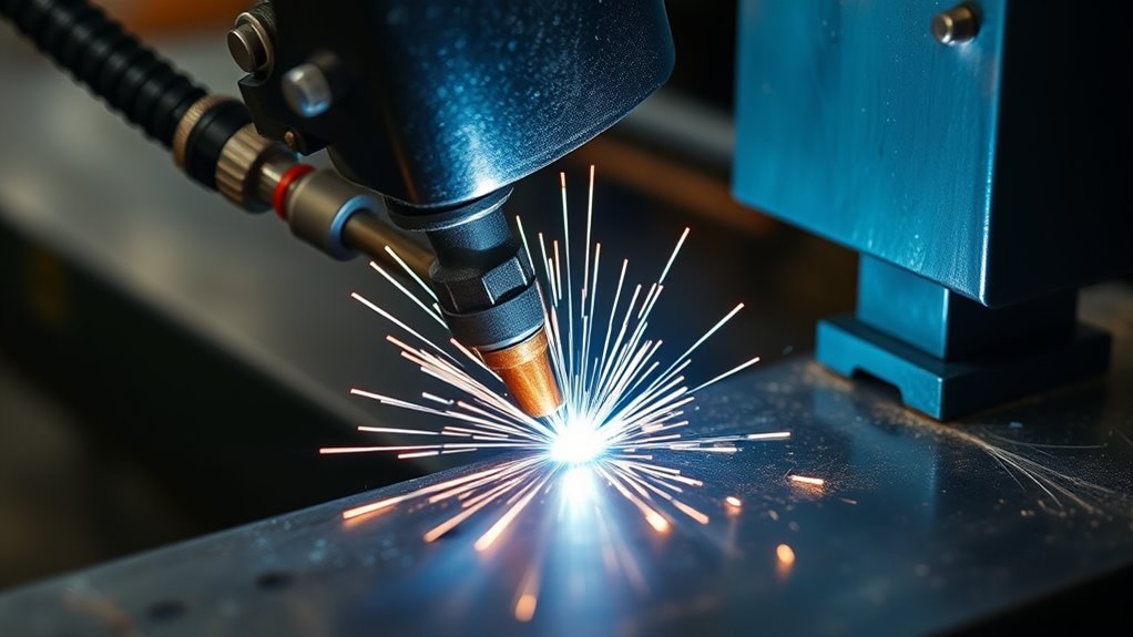
Synergic control can improve consistency when the selected program matches the job and the rest of the setup is stable. It cannot correct dirty material, a damaged liner, a poor work connection, the wrong gas, or careless torch movement.
Clean metal is especially important. Oil, mill scale, paint, moisture, heavy rust, plating, and coating residue can cause porosity, an unstable arc, or incomplete fusion. In many jobs, properly prepared surfaces produce a more predictable bead and make troubleshooting easier.
Arc Stability and Wire Feeding
A well-matched program should keep the arc within a usable range as you change the main power setting. Metal transfer should remain steady, and the wire should feed without slipping, surging, shaving, or bird-nesting.
The program cannot overcome a worn contact tip, blocked liner, excessive drive-roll tension, loose work clamp, long stickout, contaminated wire, or an incorrect gas selection. Check those mechanical and electrical items before changing software controls.
Trim and Arc Dynamics
Trim commonly changes arc length or the voltage relationship around the programmed baseline. On some machines, a positive trim creates a longer arc and a wider, flatter bead. Other machines use different numbers, names, or directions, so verify the control in the manual.
If the bead is tall and the toes do not blend into the base metal, a small trim increase may help when the program and technique are otherwise correct. If the arc is too long, harsh, or prone to undercut, a small decrease may help. Large trim changes can move the process outside the intended operating window.
Arc dynamics, inductance, or arc-control settings change how the power source reacts during metal transfer. A softer short-circuit arc may reduce harsh spatter and make the puddle feel smoother. A firmer setting may increase the arc’s driving action. The actual effect and adjustment direction vary by manufacturer and process.
Note: Change only one variable at a time. If you alter trim, stickout, travel speed, gas flow, and torch angle together, you will not know which change corrected or caused the problem.
Job Recall and Consistency
Job recall lets you save a proven machine setup and load it again. This is useful for a repeated bracket, panel, frame part, fixture, or production joint.
A saved machine job should not be the only record. Also document the wire classification and lot where required, gas, joint design, position, contact-tip-to-work distance, torch angle, travel method, preheat or interpass limits, and inspection requirements. The same machine settings can behave differently when one of those conditions changes.
Manual Controls You Still Need to Check
Synergic MIG reduces parameter setup, but it does not remove the welder’s responsibility. Before accepting the bead, check these items:
- Gas coverage: Confirm the exact gas, flow, hose condition, diffuser condition, nozzle cleanliness, and draft control.
- Contact-tip-to-work distance: Keep stickout consistent with the wire, transfer mode, and procedure.
- Wire feeding: Check drive-roll type, groove size, tension, liner, guides, spool drag, and contact-tip size.
- Work connection: Attach the clamp to clean metal and confirm that the current path will not damage sensitive parts.
- Joint fit-up: Correct large gaps, uneven edges, poor root openings, and inaccessible joint geometry.
- Surface preparation: Identify and control paint, plating, galvanizing, oil, rust, sealers, moisture, and chemical residue.
- Torch angle: Use a work and travel angle suited to the joint, position, material, and transfer mode.
- Travel speed: Moving too fast can leave a narrow bead or incomplete fusion. Moving too slowly can overheat the joint or cause excessive buildup.
- Weld sequence: Use tack placement, skip welding, backstepping, clamping, or cooling intervals when distortion matters.
Understanding shielding-gas and wire-feed problems is important because porosity or an erratic arc can look like a bad synergic program when the real problem is a leak, draft, blockage, or feed restriction.
Warning: Identify coatings and cleaners before heating the metal. Review the product safety data sheet and use the required exposure controls. Do not use chlorinated brake cleaner, chlorinated degreaser, or similar solvent on or near welding work. OSHA warns that chlorinated-solvent vapors can decompose around inert-gas arcs and form highly toxic gases. See OSHA 1926.353.
Best Applications for Synergic MIG Welding
Synergic MIG welding is most useful where a supported program can reduce setup variation without limiting the controls the job requires.
- Automotive sheet metal: Useful for repeatable starting settings and small thickness changes when the selected process matches the repair procedure.
- Automotive structural repair: Potentially useful only when the automaker’s repair procedure permits the process, wire, joint, and weld type. A machine preset does not authorize a structural repair.
- Fabrication shops: Helpful for repeat parts where saved programs reduce setup drift.
- Manufacturing: Useful for consistent changeovers across similar joints and trained operators.
- Stainless steel: Helpful when a supported program and trim control are used to manage bead profile and heat input.
- Aluminum: Useful with the correct program, wire, gas, liner, drive system, spool gun, or push-pull system.
- Training: Helpful because the operator can see how a main power control and trim affect the arc.
- Mobile repair: Useful when a compact multiprocess machine has verified programs for the consumables carried on the service vehicle.
For safety-critical, fatigue-loaded, pressure-retaining, or code-governed work, the accepted welding procedure controls the setup. The synergic program is only a way to reach or maintain those required parameters.
How to Choose a Synergic MIG Welder
Do not judge a synergic welder only by the number of programs shown in an advertisement. Check whether the programs match the work you actually perform.
- Program coverage: Confirm the supported materials, wire classifications, diameters, shielding gases, and transfer modes.
- Manual mode: A manual MIG mode is useful when a stored program does not match an unusual wire or application.
- Trim and dynamics: Check whether the machine gives enough access to fine-tune arc length and response.
- Aluminum compatibility: Verify spool-gun or push-pull compatibility, connector type, program availability, and gun amperage rating.
- Job memory: Look for enough memory locations and an easy way to name, lock, back up, or transfer jobs if several operators use the machine.
- Input power: Confirm the available voltage, phase, circuit capacity, plug, extension-cord limits, and generator compatibility.
- Duty cycle: Match the output and duty cycle to the length and amperage of the welds you expect to make.
- Gun and feeder quality: Stable wire feeding is just as important as the software.
- Service support: Check parts availability, local support, firmware updates, manuals, and consumable compatibility.
- Procedure control: Production shops may need parameter locks, user permissions, data logging, or weld monitoring.
A simple synergic machine may be ideal for occasional steel fabrication. A shop welding aluminum, stainless steel, or multiple production parts may benefit more from pulse programs, push-pull support, job memory, and process-control features.
Products Worth Considering

【6 in 1 Aluminum MIG Welder】The AWT multi-process welding machine supports various modes including Gas MIG,Gas MAG,Gasless Flux Core MIG,Stick,Aluminum MIG,and LIFT TIG (extra torch needed). With 110/220V dual voltage,MIG welder perfect for home DIY,farm work and construction sites.

FACTORY-MATCHED SPOOL GUN FOR PLUG-AND-PLAY USE: Calibrated for RBM2000. Our 2026 upgrade eliminates parameter mismatch issues common to universal spool guns, delivering steady aluminum welding with simple setup.

【5 IN 1 SMART WELDER】The SS-200M MIG welder offers 5 welding options: MIG, Gasless MIG, Spool Gun MIG (Spool Gun NOT included in pack), Stick, Lift TIG (TIG Torch NOT included in pack). Maximum current is 200Amps, supporting .030" (0.8mm), .035" (0.9mm) and .040 (1.2mm) mig wires. The MIG/Flux Core welder is capable for welding stainless steel, carbon steel, Aluminum and even thicker steel. Ideal for home maintainence, yard repairs, farm and road equipment fixing
When Synergic MIG Is Not Enough
Synergic control cannot correct every welding problem. Do not treat it as a shortcut in these situations:
- Critical structural welds: Follow the applicable WPS, code, qualification, inspection plan, drawing, and engineering requirements.
- Vehicle crash structures: Follow the current OEM repair procedure for the exact vehicle, model year, material, joint, and repair location.
- Dirty or coated metal: The machine cannot remove contamination or control fumes from a coating.
- Wrong wire or gas: A programmed relationship is valid only for the consumables it was designed to use.
- Unsupported transfer mode: A machine cannot create an acceptable pulse or spray process when the power source, gas, wire, gun, or joint is unsuitable.
- Outdoor wind: Gas-shielded MIG can lose shielding even when the voltage and wire feed are correct.
- Poor fit-up: Large gaps, uneven edges, and inaccessible roots may require joint repair, backing, tacking, or a different process.
- Restricted access: A programmed setting cannot correct a poor torch angle or excessive stickout caused by joint geometry.
- Confined spaces: Shielding gases can displace oxygen, and welding fumes can build rapidly. Entry, atmospheric testing, ventilation, and rescue controls must be established before work starts.
OSHA’s general welding requirements require welding and cutting areas to be made fire-safe. Combustibles must be moved or protected from heat, sparks, and slag before welding begins.
How Synergic Controls Save Time in the Shop
Synergic controls can shorten changeovers because the machine maintains a programmed relationship among the main arc variables. The largest benefit appears when the shop repeatedly changes between supported thicknesses or returns to a documented job.
Faster Setup
A correct program reduces the amount of wide-range searching needed to balance wire feed speed and voltage. The operator can spend more time checking fit-up, gas coverage, wire feeding, torch access, and the test coupon.
- Linked parameters reduce repeated independent adjustments.
- A programmed starting range helps prevent extreme wire-speed or voltage mismatches.
- Thickness or power changes are quicker when the selected program remains valid.
- Operators can compare the machine response with a trusted wire-speed and voltage chart while learning.
The time saving disappears when the wrong program is selected. A few extra seconds spent confirming the wire, gas, diameter, and mode can prevent a much longer troubleshooting session.
Repeatable Job Recall
Job recall can restore the program, main power value, trim, and related settings in seconds. This reduces transcription errors and makes the next setup easier to compare with the previous approved setup.
Recall does not account for a changed gas cylinder, different wire, worn contact tip, loose clamp, revised joint gap, new welding position, or a different heat sink. Treat a recalled job as a verified starting record, then make and inspect the required test weld.
Troubleshooting Synergic MIG Settings
If the weld looks wrong, do not assume the synergic program failed. Confirm the program and basic setup first, then make small corrections.
| Problem | Likely Causes | What to Check |
|---|---|---|
| Too much spatter | Wrong program or gas, dirty metal, poor work connection, long stickout, unstable feeding, or unsuitable trim | Verify the program and gas, clean the joint, inspect the clamp and feeding system, restore default trim, then adjust slightly. |
| Porosity | Gas loss, leak, blocked nozzle, draft, excessive flow, contamination, moisture, or poor torch angle | Check gas while flowing, inspect hoses and O-rings, clean the nozzle and metal, block drafts, and keep the gas envelope over the puddle. |
| Burn-through | Excessive heat, slow travel, wide gap, wrong thickness input, poor joint support, or unsuitable transfer mode | Confirm thickness and mode, reduce the programmed power or trim as allowed, increase travel speed, improve fit-up, and use a thin-metal weld sequence. |
| Cold or tall bead | Low power, fast travel, long stickout, poor work angle, wrong program, or poor electrical connection | Confirm the program, shorten stickout, correct the angle, inspect the clamp, slow slightly, or increase the approved power or trim in small steps. |
| Undercut | Long arc, excessive power, fast travel, poor angle, or failure to fill the weld toes | Reduce trim or power as permitted, correct torch angle, slow enough to fill the toes, and avoid an oversized weave. |
| Wire burn-back | Feed restriction, worn tip, incorrect tip size, excessive spool drag, unsuitable run-in or burn-back setting, or an overly long arc | Inspect the liner, guides, drive tension, tip, spool brake, stickout, trim, run-in, and burn-back controls. |
| Wire stubbing into the work | Arc too short, voltage relationship too low, wire speed too high for the program, or poor work connection | Confirm the program, inspect the clamp, restore nominal settings, and increase arc-length trim only as the manual permits. |
| Settings look right but fusion is poor | Joint design, access, travel angle, travel speed, surface condition, position, or process choice is unsuitable | Stop and review the joint preparation and required procedure. A different transfer mode, bevel, root opening, pass sequence, or welding process may be necessary. |
Frequently Asked Questions
What are the benefits of synergic welding?
The main benefits are faster initial setup, fewer extreme parameter mismatches, easier changeovers, and better repeatability when the correct program is selected. You still control wire installation, polarity, gas coverage, stickout, torch angle, travel speed, surface preparation, fit-up, testing, and inspection.
Why do welders drink milk?
Some welders drink milk because of an old belief that it prevents metal fume fever. It does not protect the lungs from inhaled welding fumes. Use effective ventilation or local exhaust, keep your head out of the plume, identify coatings, and use suitable respiratory protection when the risk assessment requires it. See Eastern Washington University’s welding-fume guidance.
Are synergic welders good?
Yes, a well-supported synergic welder can be a good choice for faster setup, repeat jobs, training, pulse welding, and frequent material changes. Its value depends on whether the installed programs match your wire, gas, materials, guns, input power, and work requirements.
What is the difference between MIG and synergic MIG?
Standard manual MIG usually requires you to set wire feed speed and voltage independently. Synergic MIG uses a stored program to keep related variables aligned as you change one main power setting. Both are forms of gas metal arc welding, and both still require proper consumables, technique, testing, and inspection.
Do professionals use synergic MIG?
Yes. Professional shops use synergic MIG for production, training, aluminum, stainless steel, pulse welding, repeat parts, and quick changeovers. Qualified welders still follow the WPS or OEM repair procedure and verify fit-up, gas, technique, heat control, and inspection requirements.
Can synergic MIG weld aluminum?
Yes, if the machine has a program for the selected aluminum wire, diameter, gas, and gun. Aluminum commonly uses argon shielding and a spool gun or push-pull system because the soft wire is difficult to push through a long standard liner. Follow the filler-metal and machine instructions for cleaning, feeding, transfer mode, and technique.
Does synergic MIG guarantee penetration?
No. The machine cannot see the root of the joint or confirm fusion. Penetration and fusion depend on joint design, access, fit-up, material thickness, surface condition, wire, gas, transfer mode, travel angle, travel speed, stickout, and heat input. Critical welds need the inspection or testing required by the governing procedure.
Can synergic mode be used with flux-cored wire?
Only when the welder has a program for the exact type or family of flux-cored wire being used. Self-shielded and gas-shielded wires have different gas and polarity requirements, and those requirements also vary by wire classification. Use the wire manufacturer’s data sheet and the machine manual.
Conclusion
Synergic MIG welding makes setup faster by linking wire feed speed, voltage, and other arc variables through a stored program. It is a strong choice for repeat work, training, frequent changeovers, and supported pulse applications. The exact controls vary by machine, so the correct wire, gas, program, gun, and manual remain essential.
The preset is only the starting point. Clean material, stable wire feeding, correct polarity, safe fume control, proper fit-up, consistent technique, a matching test coupon, and the required inspection are what turn that starting point into a reliable weld.
Sources
- Lincoln Electric, POWER MIG 350MP Operator’s Manual — supports single-knob synergic operation, linked voltage and wire-feed settings, trim, standard synergic modes, and pulsed modes.
- Fronius, MIG/MAG Synergic Welding Operating Instructions — supports material, wire-diameter, gas, and welding-power program selection for standard and pulsed synergic welding.
- Miller Electric, MIG Welding Guide — supports GMAW controls, transfer modes, shielding gases, setup variables, test-weld guidance, and defect troubleshooting.
- Miller Electric, How to Successfully MIG Weld Aluminum — supports aluminum wire-feeding systems, gun setup, cleaning, gas selection, and aluminum troubleshooting.
- OSHA, Controlling Hazardous Fume and Gases During Welding — supports local exhaust, ventilation, coating awareness, confined-space precautions, and respiratory-protection guidance.
- OSHA 1910.252, General Welding Requirements — supports fire prevention, ventilation, hazardous-fume warnings, and safe work-area controls.




