Weld penetration can look acceptable at the surface while the root remains poorly fused. The goal is not simply to make the weld go as deep as possible. You need the penetration, fusion, and weld profile required by the joint design, welding procedure specification (WPS), and governing code without causing burn-through, distortion, or other defects.
Quick Answer
Weld penetration describes how far weld metal extends into a joint, while depth of fusion describes how far melting extends into the base metal. The required amount depends on the joint design, material, load, WPS, and code. Too little can leave an incomplete root; too much can cause melt-through or excessive root reinforcement.
Key Takeaways
- Penetration, fusion, and root reinforcement are related, but they are not the same measurement.
- Complete joint penetration (CJP) and partial joint penetration (PJP) are engineered groove-weld requirements, not simple quality grades.
- Current, wire feed speed, voltage, travel speed, polarity, stickout, shielding gas, fit-up, and technique interact.
- Both overly fast and overly slow travel can reduce fusion, depending on the process and puddle control.
- A macro-etched cross-section gives direct evidence; visual inspection alone cannot prove internal penetration.
- Critical welds must follow the approved WPS, drawing, inspection plan, and applicable code.
At a Glance
| Time Required | About 10–30 minutes to prepare and weld a test coupon; longer for cutting, polishing, etching, or professional NDT |
| Difficulty | Intermediate for process tuning; advanced or qualified personnel for code inspection and NDT interpretation |
| Tools Needed | Welder, correct consumables, PPE, cleaned test coupons, measuring tools, and approved inspection equipment |
| Cost | Low for practice coupons and visual checks; laboratory sectioning and professional NDT cost more and vary by joint and code |
Warning: Welding exposes you to ultraviolet radiation, hot metal, fumes, fire, and electrical hazards. Use the correct helmet shade, protective clothing, gloves, ventilation or fume extraction, and hot-work controls. Remove coatings only with an approved method, and check the safety data sheet before welding or etching any material.
What Is Weld Penetration?
In everyday shop language, weld penetration often means how deeply the weld has melted into the joint. Formal welding terminology is more specific:
- Joint penetration is the distance weld metal extends from the weld face into the joint, excluding weld reinforcement.
- Depth of fusion is how far fusion extends into the base metal or a previous weld bead from the surface melted during welding.
- Root penetration describes how far weld metal extends into or through the joint root.
- Root reinforcement is weld metal that projects beyond the root surface. A visible root bead is not the same as proof of complete fusion.
This distinction matters because a weld may show root reinforcement but still have incomplete fusion along a sidewall. It may also have adequate fusion for its design without producing a large root bead.
Surface bead shape can provide clues, but it cannot reveal the complete internal fusion profile. You need the drawing, WPS, and inspection criteria to decide whether the result is acceptable.
You also need the correct weld size and length. Penetration does not compensate for an undersized weld, an incorrect joint detail, or unsuitable filler metal.
Why Weld Penetration Matters
Proper penetration helps the weld develop the load path intended by the designer. Inadequate root penetration or incomplete fusion can reduce the effective weld area and create sharp internal discontinuities where cracks may start.
Excessive penetration can also be unacceptable. Depending on the joint and code, it may appear as melt-through, excessive root reinforcement, root concavity beside the bead, or local thinning and distortion.
Joint Strength and Durability
Penetration affects strength only as part of the complete joint. Base-metal properties, filler-metal strength, weld size, throat, profile, discontinuities, residual stress, and loading direction also matter.
| Term | What It Means | Design Note |
|---|---|---|
| CJP groove weld | Weld metal extends through the joint thickness as required by the joint detail | Used when the design calls for complete joint penetration; it is not automatically defect-free |
| PJP groove weld | Weld metal intentionally extends only partway through the joint thickness | Can be a valid load-bearing design when sized for the applied forces |
| Fillet weld | A weld of roughly triangular cross-section joining surfaces near a right angle | Usually evaluated by leg size, effective throat, profile, and fusion to the root—not labeled CJP or PJP |
| Incomplete joint penetration | The weld does not extend as far into the joint as required | May be rejectable when it reduces the required effective weld size or violates acceptance criteria |
For structural steel, the current AWS D1.1/D1.1M:2025-AMD1 addresses design, procedure and welder qualification, fabrication, inspection, and acceptance criteria. Other industries use different codes, so do not apply one code’s rules to pressure piping, aerospace, automotive, or ship work without verification.
Defect Prevention Benefits
Controlling the joint variables helps reduce incomplete joint penetration, incomplete fusion, undercut, excessive reinforcement, and melt-through. It also improves repeatability from one part to the next.
Penetration alone does not prevent cracks or porosity. Hydrogen control, filler selection, preheat and interpass temperature, shielding, surface condition, restraint, and cooling rate may be just as important to overall weld quality.
A weld is acceptable because it meets the drawing, WPS, and inspection criteria—not because the bead merely looks deep or smooth.
Safety and Reliability
For load-bearing, pressure-retaining, fatigue-sensitive, or public-safety work, uncontrolled parameter changes can invalidate a qualified procedure or create a weld that cannot be accepted. Use the approved WPS and have changes reviewed by the responsible welding engineer, inspector, or authority.
Correct amperage settings are only one part of that control. The complete procedure may also specify process, polarity, filler classification, shielding gas, preheat, interpass temperature, joint detail, position, technique, and inspection.
Warning: Do not “tune” settings on a production structural, pressure, lifting, vehicle-safety, or fatigue-critical weld outside the approved WPS. Practice and verify changes on representative coupons first.
Complete Joint Penetration vs. Partial Joint Penetration
Complete joint penetration (CJP) means the groove weld extends through the joint thickness as required by the joint detail. Partial joint penetration (PJP) means the groove weld is intentionally designed to extend only partway through the thickness.
CJP and PJP describe groove-weld requirements. They are not a ranking in which CJP is always “good” and PJP is always “weak.” A properly designed PJP weld can carry substantial load. A CJP weld can still fail inspection if it contains unacceptable incomplete fusion, cracks, porosity, undercut, or profile defects.
The engineer selects the joint type based on load direction, fatigue demand, material thickness, access, inspectability, fabrication cost, and applicable code. CJP may require a specific bevel, root opening, root face, backing, backgouging, or welding from both sides. PJP requires a specified effective weld size and sound fusion within that required area.
Fillet welds are normally sized by leg length and effective throat. Understanding the maximum fillet weld size helps avoid confusing fillet-weld sizing with groove-weld penetration.
What Factors Affect Weld Penetration?

Penetration comes from the interaction of the welding process, machine settings, joint geometry, material, and technique. Lincoln Electric’s penetration guidance identifies variables such as current, polarity, travel speed, electrode diameter, electrode angle, arc characteristics, and shielding gas.
- Current or wire feed speed: More current generally increases arc force and melting, but excessive current can widen the puddle, create undercut, or cause melt-through.
- Voltage and arc length: These mainly affect arc length, bead width, profile, and stability. Too high or too low can produce inconsistent penetration.
- Travel speed: There is an operating window. Excessively fast travel reduces heat input and tie-in; excessively slow travel can build a large puddle that shields the base metal and produces a wide bead with poor fusion.
- Polarity: Polarity changes where heat is concentrated and affects penetration differently in SMAW, GMAW, FCAW, and GTAW.
- Electrode or wire type and diameter: Consumable classification, coating or flux, diameter, and transfer mode change arc force and puddle behavior.
- Contact-tip-to-work distance or stickout: In wire welding, an excessive or inconsistent distance changes current and arc behavior.
- Shielding gas: Gas composition affects arc energy, transfer mode, bead shape, and penetration profile.
- Joint fit-up: Root opening, groove angle, root face, alignment, and backing determine whether the arc can reach the root.
- Work and travel angles: Angles direct arc force and the molten puddle. Poor angles can cause one-sided fusion or trap slag.
- Material and thickness: Thermal conductivity, alloy, thickness, and starting temperature affect heat flow.
- Position and technique: Vertical, overhead, and out-of-position welding often require different heat and puddle control.
- Surface condition and shielding: Oil, rust, mill scale, paint, moisture, wind, and poor gas coverage can interfere with stable fusion.
Mastering welding parameters means controlling them as a system instead of changing one number without watching the rest of the arc.
How the Welding Process Changes Penetration
Each process produces a different arc and puddle, so the same adjustment does not have the same result everywhere.
- SMAW: Electrode classification, diameter, polarity, arc length, angle, amperage, and travel speed strongly affect root access and slag control.
- GMAW/MIG: Wire feed speed largely controls amperage on constant-voltage equipment, while voltage controls arc length and bead profile. Transfer mode, gas, wire diameter, and stickout also matter. Use the machine chart or a manufacturer calculator as a starting point.
- FCAW: Wire type, polarity, stickout, shielding method, and slag behavior can make the penetration profile different from solid-wire GMAW.
- GTAW/TIG: Current, polarity, arc length, torch angle, travel speed, and filler addition control a small, precise puddle. A long arc spreads heat and can reduce control at the root.
Choose the welding process based on material, thickness, position, access, required productivity, and procedure—not only on which process appears to penetrate deepest.
Products Worth Considering

3-in-1 Multi Process Welder: Designed to handle Gasless MIG welder, MMA, and Lift TIG perfectly, this 110V welding machine is a garage essential for home DIY and fast farm repairs.(Lift TIG Torch NOT included)
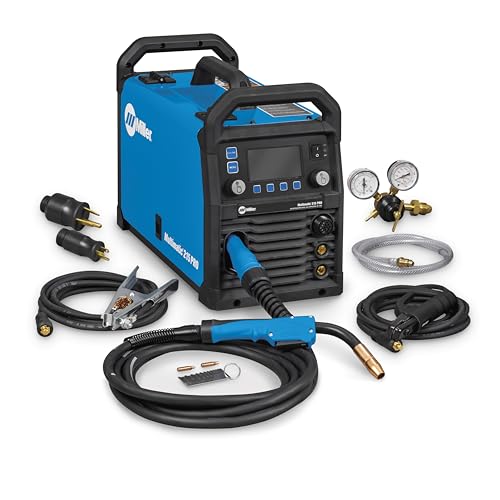
Versatile Performance — Pulsed MIG & Pulsed TIG: This multiprocess welder handles MIG, Pulsed MIG, TIG, Pulsed TIG, and Stick; Auto-Set provides fast settings; powered by continually upgradable USB software

6-IN-1 Multifunctional Welder Machine: This 6-in-1 multi welder supports FLUX MIG, GAS MIG, PLASMA CUTTING, HF TIG, and STICK,SPOT welding, provide a comprehensive solution for a wide range of welding and cutting tasks, suitable for both home DIY and industrial projects.
How to Increase Weld Penetration
Start with a representative test coupon and the approved parameter range. Increase penetration in small, controlled steps:
- Confirm the joint detail. Check the groove angle, root opening, root face, alignment, backing, and access against the drawing or WPS.
- Clean the joint. Remove oil, moisture, heavy rust, scale, and coatings using an approved method.
- Set the correct consumable and polarity. Verify wire or electrode type, diameter, polarity, and shielding gas before changing heat.
- Increase current within the approved range. On many wire processes, that means increasing wire feed speed while keeping the arc stable.
- Correct voltage or arc length. Aim for a stable arc and proper bead shape rather than assuming higher voltage always means deeper penetration.
- Bring travel speed into the proper window. Slow down only when travel is clearly too fast. If the puddle becomes oversized and rolls ahead of the arc, increase speed or reduce deposition.
- Improve arc placement. Hold the specified work and travel angles and keep the arc at the leading portion of the puddle so it can reach the root and sidewalls.
- Control stickout or arc length. Keep contact-tip-to-work distance or tungsten arc length consistent with the procedure.
- Verify the result. Use the required coupon test, macrosection, bend test, or NDT method before production.
For GMAW, follow the wire manufacturer or equipment chart. Miller notes that wire feed speed affects amperage and penetration, while voltage controls bead height, width, and arc stability. Its guidance also shows that travel that is too fast or too slow can both produce poor penetration.
TIG, MIG, FCAW, and SMAW require different adjustments. Do not transfer a setting rule from one process to another without checking the procedure and manufacturer data.
Clean, consistent cut edges help fit-up, but cutting consumables do not directly create weld penetration. A well-controlled cut made with the correct thin-steel cutting setup can reduce gaps, dross, and edge damage before welding.
Pro Tip: Record amperage or wire feed speed, voltage, travel speed, stickout, gas, polarity, joint gap, and result for each coupon. Change one variable at a time so you can identify what actually improved the root and sidewall fusion.
Products Worth Considering

COMPLETE PRACTICE SET: Includes 6 welding practice coupons, each 2" x 4" and 3 mm thick; compact mild steel plates form a convenient welding starter kit

COMPLETE PRACTICE SET: Includes 24 welding practice coupons, each 2" x 4" and 3 mm thick; compact mild steel plates form a convenient welding starter kit

Standard Size Welding Coupons: The Certiweld Supplies TIG welding accessories are designed to provide uniformity in welding instruction, testing, and practice for MIG, TIG, and stick welding procedures, being incredibly versatile.
How to Reduce Excessive Weld Penetration
Excessive penetration may appear as melt-through, an oversized root bead, root sagging, local thinning, distortion, or poor root contour. Reduce it without creating a cold weld:
- Lower current or wire feed speed in small steps while maintaining a stable arc.
- Increase travel speed slightly if the puddle is lingering or falling through the root.
- Correct excessive root opening, a thin root face, or poor alignment—but only within the approved joint detail.
- Use the specified smaller wire, electrode, or filler size when thin material requires finer control.
- Use pulse, a backing bar, chill bar, or heat sink only when the process and procedure permit it.
- Reduce weaving or dwell at the root and keep the arc moving in the leading portion of the puddle.
- Use a sequence that limits distortion and heat buildup on long or restrained joints.
Do not lower heat until the bead merely sits on the surface. The correct result is the required fusion and penetration with an acceptable root and face profile.
How to Measure Weld Penetration
The best method depends on whether you are qualifying a procedure, checking production, investigating a failure, or training. Acceptance must come from the applicable drawing, specification, or code.
Macro-Etched Cross-Section Analysis
A macrosection is one of the clearest ways to examine penetration and fusion directly. You cut through a representative weld, prepare the surface, polish it, and apply a suitable etchant so the fusion boundary becomes visible.
ISO 17639:2022 gives recommendations for specimen preparation and macroscopic and microscopic examination of welds. A calibrated microscope or image-analysis system can then measure joint penetration, depth of fusion, throat, and other dimensions.
Sample location matters. A single cut may miss a start, stop, crater, or intermittent defect, so the inspection plan should define how many sections to take and where.
Warning: Cutting, grinding, polishing, and chemical etching create separate hazards. Guard rotating equipment, control sparks and dust, wear eye and face protection, and use the etchant only with the required gloves, ventilation, storage, and disposal controls listed in its safety data sheet.
Visual Inspection Methods
Visual inspection can find surface discontinuities and signs that settings may be wrong, but it cannot prove internal penetration by itself.
| Indicator | Possible Meaning | Limitation |
|---|---|---|
| Narrow, high bead with poor toe tie-in | Travel too fast, current too low, voltage too low, or poor angle | Internal root condition remains unknown |
| Very wide bead or puddle rolling ahead | Travel too slow, excess deposition, or poor arc placement | A wide bead can still have shallow fusion |
| Large or sagging root bead | Excess heat, root gap, or dwell | Visible reinforcement does not prove complete sidewall fusion |
| Undercut, overlap, or arc strikes | Technique or parameter problems | These are separate discontinuities with their own acceptance limits |
Non-Destructive Testing and Measurement Tools
Non-destructive testing can assess internal discontinuities without cutting the finished part, but no single NDT method proves penetration in every joint.
- Ultrasonic testing (UT): Useful for many full-penetration welds when material, thickness, geometry, surface access, calibration, and procedure are suitable. ISO 17640:2018 is primarily intended for full-penetration, low-attenuation metallic welds at least 8 mm thick; special applications require defined procedures.
- Radiographic testing (RT): Can reveal many internal volumetric and root-area conditions in suitable plate and pipe geometry. ISO 17636-1:2022 covers film radiography techniques, while acceptance levels come from other applicable standards or specifications.
- Phased-array UT and automated methods: Can provide detailed encoded data but require qualified procedures, calibration blocks, trained personnel, and geometry that supports reliable interpretation.
- Bend, fracture, or fillet-break tests: Destructive tests can expose lack of fusion or root problems during procedure or performance qualification, but they do not replace the required production inspection plan.
Digital microscopes and calibrated software are useful after sectioning, but calibration does not correct poor specimen preparation or an unrepresentative sample.
Note: UT and RT applicability depends on joint geometry, material, thickness, defect orientation, access, and code. Critical inspection should be performed and interpreted by qualified personnel using a written procedure.
Weld Penetration Troubleshooting
| Problem | Likely Causes | Corrective Direction |
|---|---|---|
| Incomplete root penetration | Root gap too tight, root face too thick, current too low, travel too fast, poor arc access | Restore approved fit-up, correct current and speed, and place the arc at the root |
| Sidewall lack of fusion | Poor angle, puddle ahead of arc, scale, low heat at sidewall, excessive weave | Clean the groove, correct angle and arc placement, and control puddle size |
| Melt-through or sagging root | Current too high, root gap too wide, root face too thin, travel too slow | Reduce heat, correct fit-up, increase travel slightly, or use approved backing/pulse |
| Inconsistent penetration | Changing stickout, arc length, speed, angle, gap, or gas coverage | Stabilize technique, fixtures, fit-up, and machine settings; check consumable feeding |
| Good-looking face but failed macro | Arc heat stayed in filler metal or puddle instead of reaching root and sidewalls | Reduce puddle size, improve arc placement, revise fit-up or parameters, then retest |
Common Weld Penetration Mistakes
- Treating “more penetration” as automatically stronger: The correct amount is the amount required by the joint design.
- Confusing root reinforcement with fusion: A bead visible on the back does not prove both sidewalls fused.
- Slowing down without watching the puddle: Excessively slow travel can produce a large, cold-lapping puddle with poor fusion.
- Changing several settings at once: You lose the ability to identify which variable caused the result.
- Ignoring polarity, stickout, gas, or transfer mode: These can change the penetration profile even when displayed amperage and voltage look similar.
- Skipping joint preparation: Dirty edges, incorrect bevels, tight roots, and poor alignment can block access to the root.
- Using one process rule for every process: TIG, MIG, FCAW, and stick respond differently.
- Relying only on bead appearance: A smooth face can hide incomplete joint penetration or incomplete fusion.
- Working outside the WPS: Unauthorized changes can make a critical weld noncompliant even if it appears sound.
Test coupons help you find the correct balance before you weld the final part. For stainless work, proper heat input management also helps control distortion, oxidation, and procedure limits.
Frequently Asked Questions
Why is weld penetration important?
Penetration helps establish the effective load path through a groove weld. Too little may leave an incomplete root or reduce effective weld size. The required amount must come from the drawing, WPS, and applicable code rather than from appearance alone.
How much penetration should a weld have?
It should have the joint penetration specified by the design. A CJP groove weld must extend through the required joint thickness. A PJP groove weld needs the specified effective size. Fillet welds are normally judged by size, throat, profile, and fusion requirements.
Can a weld have too much penetration?
Yes. Excessive penetration can produce melt-through, excessive root reinforcement, sagging, local thinning, distortion, or an unacceptable root contour. Reduce heat or dwell and correct the joint gap within the approved procedure.
Does more amperage always mean better penetration?
No. More current often increases melting and arc force, but excessive current can cause undercut, an oversized puddle, spatter, distortion, or melt-through. It must be balanced with voltage, travel speed, joint fit-up, consumable, polarity, and position.
Can you check penetration without cutting the weld?
Sometimes. UT, RT, phased-array UT, or another approved method may assess internal conditions when the material and geometry are suitable. Visual inspection cannot prove internal penetration. The inspection method must match the code, joint, thickness, access, and discontinuity being sought.
Is deeper penetration always a stronger weld?
No. Strength depends on the complete joint design, effective weld area, material and filler properties, profile, discontinuities, and loading. Penetration beyond what the design requires may add heat and distortion without improving capacity.
What is the difference between penetration and fusion?
Joint penetration measures how far weld metal extends into the joint. Depth of fusion measures how far melting extends into the base metal or a previous bead. A weld can have visible root metal yet still lack fusion along a sidewall.
Can I judge penetration from the back of the weld?
A visible root bead can show that weld metal reached beyond the root surface, but it does not prove complete sidewall fusion or code acceptance. Use the required inspection or qualification method for the joint.
Conclusion
Weld penetration is not a surface beauty test and it is not a contest to produce the deepest bead. The correct target comes from the joint design, WPS, material, service load, and governing acceptance criteria.
Control fit-up first, then balance current, voltage, travel speed, polarity, stickout, gas, and technique. Verify the result on representative coupons with the inspection method the job requires. When you separate penetration from fusion and follow a qualified procedure, you produce welds that are safer, more repeatable, and easier to inspect.
Sources
- American Welding Society — AWS D1.1/D1.1M:2025-AMD1 — current structural-steel requirements for procedure qualification, fabrication, inspection, and acceptance.
- Lincoln Electric — Variables That Affect Weld Penetration — effects of current, polarity, travel speed, electrode variables, angle, and shielding gas.
- Miller Electric — Five Steps to Improving Stick Welding Technique — travel-speed and puddle-control guidance.
- ISO 17639:2022 — specimen preparation and macro/micro examination of welds.
- ISO 17640:2018 — ultrasonic testing techniques, testing levels, and assessment scope.
- OSHA — Welding, Cutting, and Brazing Hazards and Solutions — welding fume, radiation, burn, electrical, and PPE safety guidance.