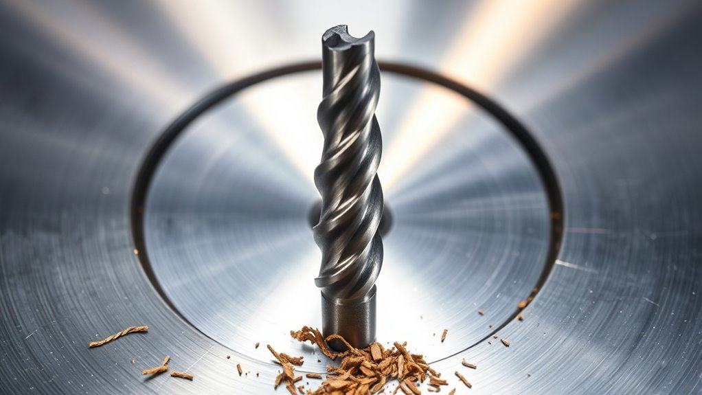
A spot weld drill bit helps separate welded sheet-metal panels while limiting damage to the flange or panel underneath. Clean removal depends on using the correct type and diameter of cutter, following the vehicle or equipment repair procedure, supporting the work, and stopping as soon as the upper layer releases.
Quick Answer
Use a spot weld drill bit by exposing and marking the weld, selecting a cutter that fits its design and diameter, securing the work, and drilling squarely at the manufacturer’s recommended speed. Apply steady feed, avoid side pressure, and stop when the upper panel releases rather than drilling through both layers.
Key Takeaways
- Annular spot-weld cutters and solid spot-weld drill bits remove metal differently, so their sizing and setup are not interchangeable.
- For vehicle work, check the body repair information for the exact model year, body configuration, material, and joint before drilling.
- Use eye protection with side coverage, secure the work, remove the chuck key, and keep hair, clothing, jewelry, and gloves away from rotating parts.
- Follow the cutter manufacturer’s speed, feed, and lubricant instructions instead of relying on one universal RPM.
- Stop when the upper panel releases. Do not keep drilling until a full hole appears through the lower panel.
- Clean away chips, inspect the retained flange, and restore corrosion protection as required by the repair procedure.
At a Glance
| Time Required | Usually several minutes per accessible weld after preparation; coatings, adhesive, hardened steel, and poor access add time. |
| Difficulty | Moderate. Depth control becomes harder on curved, layered, structural, or high-strength panels. |
| Tools Needed | Variable-speed drill or approved pneumatic tool, suitable cutter, marker, measuring tool, weld-cleaning tool, clamps or stable support, panel separator, PPE, and approved cutting lubricant when required. |
| Cost | Low if you already own a suitable drill. Solid-carbide cutters, pneumatic depth-control drills, and replacement cutting heads cost more. |
What’s in This Article
- What Is a Spot Weld Drill Bit?
- Types of Spot Weld Cutters and Drill Bits
- Check Repair Information and Vehicle Safety
- How to Set Up Your Drill
- Essential Safety Gear
- How to Choose the Right Size
- How to Find and Mark Spot Welds
- How to Drill Out Spot Welds
- How to Manage Heat
- Common Issues and Troubleshooting
- Separating and Preparing the Panels
- How to Maintain Spot Weld Bits
- Alternative Removal Methods
- When to Replace a Spot Weld Bit
- Frequently Asked Questions
- Conclusion
- Sources
What Is a Spot Weld Drill Bit?
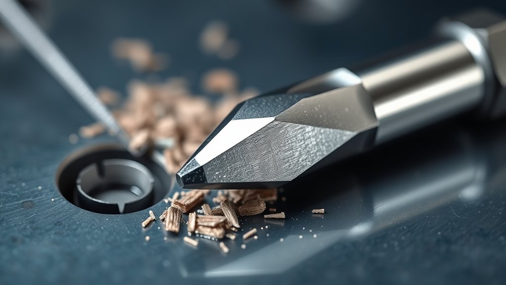
A spot weld drill bit is a cutting tool made to remove or release resistance spot welds. Factory spot welding joins overlapping metal by creating a fused area called a weld nugget. To separate the sheets, you remove the nugget from the panel being discarded or cut a ring around it.
Dedicated tools provide better depth control than a standard twist drill. That reduces the chance of making a full hole through both sheets, although no cutter can guarantee that the retained panel will remain untouched.
Some systems use high-speed steel, high-speed cobalt, or solid-carbide cutting edges. The correct material depends on the cutter design and the steel being drilled. Hardened automotive steel can quickly dull a cutter intended only for mild sheet steel.
Flux-core welding can be useful for general fabrication, but it is not automatically approved for replacing automotive factory welds. Panel reattachment must follow the applicable OEM procedure.
Types of Spot Weld Cutters and Drill Bits
Products Worth Considering

Product Content: You will receive 3 pieces of spot weld drill bits, a set to easily handle common automotive and metalworking needs.

Durable Material : The preferred material used was top-quality steel which has excellent thermal resistance.The cutting blade has a diameter of 3/8 inches, and the arbor is of standard 1/4 inch size.
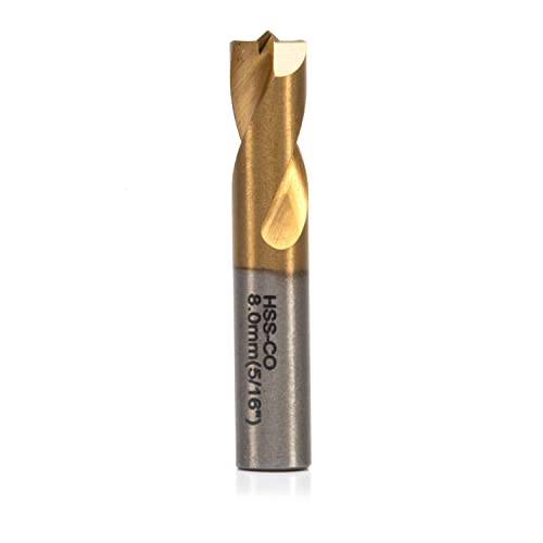
[APPLICATION]: Use this spot weld drill bit to separate spot welds and resistance spot welding panels without distorting the sheet metal.
Annular Spot-Weld Cutters
An annular cutter has a hollow cutting head. It cuts a ring around the weld and leaves a small metal plug or button in the center. This design is useful when the upper panel will be discarded and the lower panel must be retained.
Many annular cutters use a replaceable or reversible cutting head and a pilot pin. The pilot helps center the tool, while the cutting teeth remove only the ring of metal around the weld.
Annular cutters must be large enough to surround the fused nugget. Matching the cutter diameter to the visible dimple alone may leave part of the weld attached.
Solid Spot-Weld Drill Bits
A solid spot-weld drill has a flat or specially ground cutting face that drills into the weld rather than around it. Automotive versions are commonly made from HSCO or carbide and may be used in a hand drill or a dedicated pneumatic spot-weld drill.
Solid bits are often easier to place in tight areas, but they can penetrate the lower sheet if you continue drilling after the upper layer releases.
Pneumatic Depth-Control Drills
A dedicated pneumatic spot-weld drill may include an adjustable depth stop, clamp, or controlled-feed mechanism. These tools are common in collision-repair work because they improve repeatability across many welds.
The tool’s compatible bits, air pressure, feed control, and depth adjustment must follow its instructions. Do not assume that a bit made for one spot-weld drill will fit or perform correctly in another.
Abrasive Removal Tools
Belt files, small abrasive discs, and carbide burrs expose or grind away the weld from one side. They can work well on awkward joints or hardened material, but they require close visual control and can thin the retained flange.
Note: “Spot weld drill bit” is often used as a broad label. Before choosing a size or speed, identify whether your tool cuts around the nugget, through the nugget, or grinds it away.
Check Repair Information and Vehicle Safety
On a vehicle, removing the old panel is only one part of the repair. Before drilling, obtain the body repair information for the exact year, model, body style, powertrain, and repair location. Construction and approved attachment methods can change between model years.
I-CAR’s summary of Nissan repair guidance explains why the correct vehicle-specific body repair manual matters. The procedure may specify whether the replacement joint uses resistance spot welds, plug welds, rivets, adhesive, or another method.
- Confirm whether the panel, reinforcement, rail, pillar, rocker, or flange may be removed at the planned location.
- Identify the metal type and whether it includes mild steel, high-strength steel, ultra-high-strength steel, boron steel, or aluminum.
- Locate wiring harnesses, restraint-system parts, fuel lines, brake lines, coolant lines, refrigerant lines, glass, and interior trim behind the drilling area.
- Follow the OEM shutdown and battery-disconnection procedure before working near electrical, airbag, or pyrotechnic components.
- Inspect the seam for adhesive or seam sealer that may continue to hold the panel after the welds are released.
Warning: Do not drill, cut, or pry near an electric or hybrid vehicle’s orange high-voltage cables, battery, connectors, or damaged high-voltage components unless you are trained and have completed the exact OEM de-energizing procedure. Treat exposed high-voltage parts as energized.
The National Highway Traffic Safety Administration warns that exposed high-voltage components can create shock hazards and that damaged batteries may release flammable or toxic gases. Move the job to qualified personnel when the repair involves an HV battery, damaged HV cable, or an uncertain isolation state.
Tools and Materials Checklist
- Vehicle-specific or equipment-specific repair procedure
- Variable-speed drill, approved pneumatic drill, or cutter arbor
- Correct annular cutter or solid spot-weld bit
- Calipers, ruler, or cutter-sizing gauge
- Marker, inspection light, and shallow center punch when permitted
- Abrasive disc, wire brush, scraper, or belt file for exposing welds
- Clamps, stands, or another stable way to support the work
- Panel-separation knife, seam splitter, or thin panel chisel
- Approved cutting fluid when specified by the cutter manufacturer
- Safety glasses with side protection, hearing protection, and any respiratory protection selected for the actual hazard
- Chip brush, magnet, vacuum rated for the debris, and cleaning materials
How to Set Up Your Drill for Removing Spot Welds
Use a drill that gives you stable, variable-speed control. Turn off hammer mode. A compact right-angle drill or pneumatic spot-weld drill may provide better alignment in restricted areas.
Drill Type Selection
Match the drill to the cutter shank, required speed range, access, and material. A standard variable-speed hand drill can operate many small cutters, while specialized carbide bits may require the compatible pneumatic tool.
Use a side handle when the drill manufacturer supplies one and space allows it. Binding can create sudden reaction torque, so keep a balanced stance and maintain control with both hands when practical.
Do not hold a loose panel in your hand while drilling. Clamp it or support it on a stable surface. A drill manufacturer’s safety instructions require the material to be secured rather than held against the body.
Bit Size Measurement
Measure the visible weld impression only after removing enough coating to see its edge. Then consider the cutter design:
- Annular cutter: Choose a diameter that fully surrounds the fused nugget without removing unnecessary flange material.
- Solid spot-weld drill: Use the size specified by the tool maker or repair procedure for the weld and material.
- Unknown or irregular weld: Begin with inspection and OEM information rather than guessing from a generic chart.
Proper Chuck Tightness
Disconnect the drill’s battery or unplug the tool before installing or changing the cutter. Insert the shank far enough for the chuck jaws to grip it securely without clamping on the cutting flutes.
If the drill uses a keyed chuck, tighten the chuck evenly at each key position. Remove the chuck key before reconnecting power. For a keyless chuck, follow the drill manual and pull on the installed cutter to confirm that it is locked.
Check for a bent arbor, loose cutting head, damaged pilot, or chipped tooth. A loose or damaged cutter can chatter, walk, bind, or break.
Speed and Feed Setup
There is no single RPM for every spot-weld bit. Use the speed listed for the cutter, material, and drill system. For example, Blair states that its annular spot-weld cutters should not exceed 500 RPM, while other solid bits and dedicated drills may use different speeds.
Start under control and establish a clean cut before increasing feed. Do not run a large cutter at the drill’s maximum speed simply because the drill can reach it.
Use cutting fluid only when the cutter manufacturer allows it and when it will not create a contamination problem for later bonding, refinishing, or welding. Keep oil off drill handles and clean it completely from the repair area afterward.
Essential Safety Gear for Using Spot Weld Drill Bits
Metal chips can leave the cut at high speed. Wear safety glasses with side protection. Add a face shield over the glasses when the work position or chip direction creates added facial exposure.
Use hearing protection when required by the tool instructions, workplace assessment, or noise level. Keep nearby people outside the chip path and provide them with suitable protection.
Control dust at the source. Remove loose dirt and coatings carefully, use local ventilation or extraction when practical, and identify the coating before choosing respiratory protection. OSHA states that engineering controls such as ventilation should be used as far as feasible before relying on respirators.
For additional background on coated metal, see the discussion of health risks around galvanized steel. Drilling or grinding coatings can produce dust, while later heating or welding can create additional fumes.
Wear cut-resistant gloves while handling sharp sheet-metal edges, moving a stopped panel, or touching a cooled cutter. Keep gloves away from the rotating chuck, pilot, and cutting head. Tie back long hair, remove jewelry, and keep loose sleeves clear.
Review a complete PPE checklist before performing any later welding operation.
Warning: Disconnect the drill battery or power before changing cutters, clearing a jam, adjusting a depth stop, or removing a metal plug. Never use your fingers near a cutter that can start unexpectedly.
Products Worth Considering
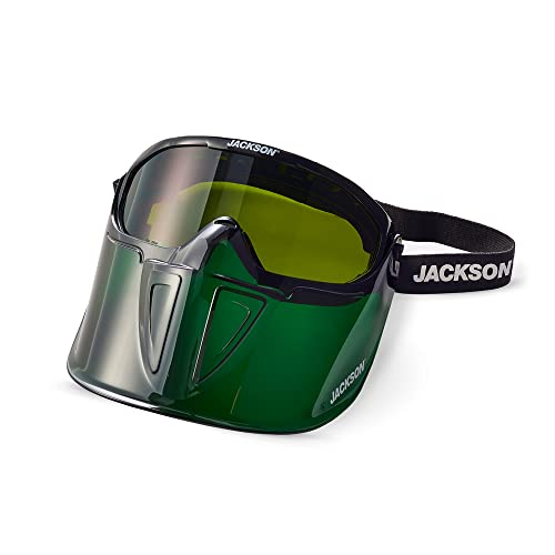
EYE & FACE PROTECTION - Jackson Safety’s GPL550 Safety Goggles with a detachable flip-up face shield ensure your safety in the most demanding environments with indirect vents and anti-fog coating

EYE & FACE PROTECTION - Jackson Safety’s GPL530 Safety Goggles with a detachable flip-up face shield ensure your safety in the most demanding environments with indirect vents and anti-fog coating
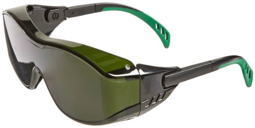
One-piece polycarbonate lens fits over most prescription glasses
How to Choose the Right Size Spot Weld Bit
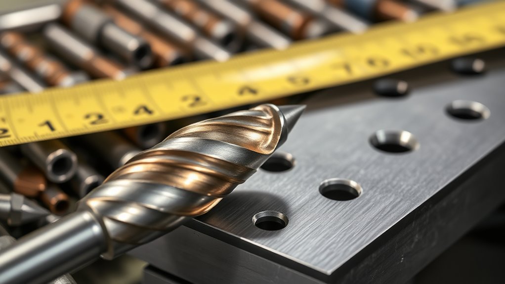
The correct cutter is the smallest approved size that fully releases the weld without removing unnecessary material from the retained flange. This is not always the same as the diameter of the surface dimple.
Measuring the Weld
Clean the surface until the weld boundary is visible. Use calipers, a ruler, or the cutter maker’s sizing guide. On an annular cutter, confirm that the cutting ring will pass outside the entire nugget.
Check more than one weld. Factory impressions can vary across a seam, and corrosion, paint, sealer, or previous repairs can make a weld look larger or smaller than it is.
| Tool Type | How to Select the Diameter | Best Fit | Main Caution |
|---|---|---|---|
| Annular cutter | Use a cutting ring that completely surrounds the nugget. | Removing a panel while retaining the flange below | An undersized ring leaves part of the weld attached. |
| Solid spot-weld drill | Use the tool maker’s recommended size for the weld and material. | Tight access and dedicated pneumatic drill systems | It can penetrate the lower sheet if drilling continues too long. |
| Abrasive disc or belt file | No fixed diameter; expose only the weld area. | Irregular welds, hardened material, and limited cutter access | Easy to thin or gouge the retained flange. |
Common Cutter Diameters Explained
Six-, seven-, eight-, ten-, and twelve-millimeter cutters are available in some product lines, but those numbers describe the tool, not a universal automotive weld standard.
| Example Cutter Size | Selection Check | Risk if Misused |
|---|---|---|
| 6–7 mm | Use only when the cutter fully releases the small nugget and the tool maker approves the application. | May leave the outer part of a larger weld attached. |
| 8 mm | Commonly offered for body-repair tools; verify the actual nugget and bit system. | Can still be too small or too large for the specific joint. |
| 10 mm | Consider only when a larger weld, cutter design, or procedure requires it. | Removes more flange material than a smaller cutter. |
| 12 mm | Treat as a specialty size and confirm surrounding clearance. | May create an unnecessarily large repair area. |
A discussion of maximum fillet weld size concerns a different joint type. Fillet-weld dimensions should not be used to choose a spot-weld cutter.
High-Strength and Boron Steel Considerations
High-strength and boron steels can dull ordinary high-speed-steel cutters quickly. Use only a cutter approved for that material. Solid carbide may improve cutting performance, but carbide is brittle and can chip if the tool is tilted or side-loaded.
Do not heat hardened vehicle steel to soften it. Heat can change material properties and damage nearby coatings, adhesive, wiring, or trim.
If the cutter barely marks the weld, stop and verify the steel grade and tool. Applying more force to the wrong cutter increases the chance of breakage and panel damage.
How to Find and Mark Spot Welds
Factory welds may appear as shallow circles, dimples, slight depressions, or changes in reflected light. Paint, undercoating, seam sealer, corrosion, and body filler can hide them.
- Use the repair procedure or an undamaged reference panel to identify the seam and expected weld pattern.
- Remove trim, sealer, or coating only as far as needed to expose the joint.
- Use a small abrasive disc, wire brush, scraper, or belt file without thinning the sheet.
- Shine a light across the surface at a low angle to make depressions easier to see.
- Mark the center and outside edge of each suspected weld.
- Check the back of the flange when access is available.
If the cutter requires a center mark, make a shallow punch point. A deep punch can deform thin sheet metal or make a brittle carbide cutter start unevenly. Some piloted or clamping systems do not need a separate center-punch mark.
Do not automatically drill a small pilot hole through the weld. A dedicated cutter may already have a pilot, and a full pilot hole can damage the retained sheet before the main cutter begins working.
Essential Technique: How to Drill Out Spot Welds
The goal is not to make a hole through the joint. The goal is to remove enough of the weld from one sheet for the panels to separate without unnecessary loss of metal.
- Confirm the repair plan. Verify the joint, material, replacement method, and vehicle-system precautions before removing any weld.
- Expose the weld. Remove only enough paint, corrosion, sealer, or coating to see its boundary.
- Support the work. Clamp a loose panel or stabilize the vehicle panel so movement does not make the cutter chatter.
- Select the cutter. Choose the correct type, diameter, cutting material, and compatible arbor or drill.
- Install it securely. Disconnect power, tighten the chuck or arbor, inspect the cutter, and remove the chuck key.
- Set speed and lubrication. Follow the cutter manufacturer’s RPM, air-pressure, depth-stop, and lubricant instructions.
- Align the drill. Hold the cutter square to the local panel surface. A curved panel may require changing the drill angle from one weld to the next.
- Begin the cut. Start under control and apply steady axial feed. Do not lean the drill sideways or use the cutter as a pry tool.
- Watch for release. Look for a complete cutting ring, a change in chip pattern or sound, or slight movement of the upper sheet. Stop and inspect often.
- Separate gently. Insert a thin panel separator at the seam and test the joint. If it remains firm at one spot, locate the remaining weld material instead of forcing the panels apart.
Pro Tip: Place a bright inspection light behind an accessible flange. As the upper sheet becomes thin, a slight change in light, color, or panel movement may help you stop before entering the lower sheet.
How to Recognize Breakthrough
Depth cues vary with tool design, but common signs include:
- A complete ring of clean chips from an annular cutter
- A sudden reduction in feed resistance
- A change in cutting sound
- Slight movement between the two sheets
- A visible line around the released weld
- The panel separator beginning to enter the seam without heavy force
Stop immediately when the upper sheet releases. Do not wait for the cutter to drop into the lower panel.
How to Manage Heat When Drilling Spot Welds
Heat rises when the speed is too high, the edge is dull, the cutter rubs instead of cutting, chips become trapped, or the tool is side-loaded.
Use the cutter maker’s recommended speed and a steady feed that produces chips. Excessive force can break teeth or bend the pilot, but almost no feed can polish the surface and overheat the edge.
Clear packed chips after disconnecting power. Use a brush, magnet, or appropriate tool rather than your fingers. Apply approved cutting fluid in small amounts when permitted.
Let an overheated cutter cool naturally. Avoid quenching a hot carbide cutter because sudden temperature change can contribute to cracking.
Replace or sharpen a dull cutter only as allowed by its manufacturer. Continuing with a dull edge encourages harder pushing, greater heat, and poorer depth control.
If zinc or another coating must be removed for the later repair, follow the repair and product instructions. Review safe methods for handling zinc-coated steel and restore required corrosion protection after the repair.
Common Issues With Spot Weld Drill Bits
| Problem | Likely Cause | Correction |
|---|---|---|
| Cutter walks off the weld | Poor centering, curved surface, damaged pilot, or starting too fast | Remark the center, use the approved pilot method, start under control, and keep the tool square. |
| Heavy chatter | Loose work, loose chuck, bent arbor, side pressure, or worn teeth | Secure the work, retighten the cutter, inspect the arbor, and correct alignment. |
| Little or no cutting | Dull edge, wrong rotation, hardened material, glazed coating, or insufficient feed | Stop and verify the bit, material, rotation, speed, and feed rather than forcing the tool. |
| Blue or burned cutter | Excess speed, rubbing, dull teeth, poor chip clearance, or missing approved lubricant | Stop, let it cool, clean the cut, lower speed as directed, and replace a damaged edge. |
| Broken pilot or chipped teeth | Tilting, side-loading, impact, loose setup, or using the wrong cutter on hardened steel | Replace the damaged part and correct the tool, material, and alignment before continuing. |
| Lower panel drilled through | Drilling continued after release or the depth stop was set incorrectly | Stop, document the damage, and use the OEM-approved repair method for the retained flange. |
| Panel will not separate | Part of the nugget remains, another weld was missed, or adhesive/sealer still holds the seam | Inspect the seam, find the remaining attachment, and avoid bending the flange with force. |
| Plug stuck in annular cutter | Packed chips, damaged ejector, or insufficient cleaning | Disconnect power and clear it using the manufacturer’s procedure and a suitable tool. |
Good ventilation practices also apply when surface preparation creates dust. Do not treat an ordinary nuisance-dust mask as suitable for every paint, primer, sealer, corrosion product, or metal contaminant.
Separating and Preparing the Panels
After the welds are cut, begin separation at an accessible edge. Slide a thin panel knife or seam splitter between the sheets and use controlled pressure.
Do not drive a thick chisel deeply between panels that must be reused. It can stretch the flange, tear the edge, or create high spots that prevent the replacement panel from fitting correctly.
If the joint opens at most welds but remains tight in one area, stop and inspect. Common causes include:
- An incompletely cut nugget
- A hidden second row of welds
- A braze, rivet, or previous repair
- Structural adhesive or seam sealer
- A folded or mechanically locked flange
Once the panel is removed, vacuum or collect metal chips from cavities, trim, carpet, wiring channels, and drain paths. Loose steel chips can rust, damage finishes, or cause electrical problems.
Remove burrs without thinning the retained flange. Inspect every drilled location for cracks, enlarged holes, deep gouges, and accidental penetration. Repair damage only by the approved procedure.
Clean away cutting oil before adhesive, primer, seam sealer, or welding preparation. Apply weld-through primer, cavity wax, epoxy primer, or other corrosion protection only where the OEM and product instructions require it.
How to Maintain and Care for Spot Weld Bits
Clean the cutter after each use. Metal plugs and chips trapped around the teeth can affect the next cut and prevent a pilot or ejector from moving correctly.
Inspect the following parts before storage and before the next job:
- Cutting teeth or flutes for chips, rounding, or uneven wear
- Pilot pins for bending, mushrooming, or sticking
- Arbors and shanks for bending or scoring
- Set screws, retaining threads, and replaceable heads for looseness
- Depth stops and clamps for free movement
Use only lubricant approved for the cutter and work material. More oil is not always better, especially when the panel will later receive adhesive or refinishing materials.
Some annular heads can be reversed or replaced. Do not reverse, sharpen, or grind a cutter unless its manufacturer permits that service.
Store the cutter in a case or holder so its edges cannot strike other tools. Protect solid-carbide bits from drops and side impacts.
When a grinder is part of the maintenance or removal process, follow appropriate spark and fire precautions.
Alternative Methods for Removing Spot Welds
A drill is not always the best option. Access, material hardness, panel shape, and the condition of the retained flange may make another method safer or faster.
- Belt file: Removes the weld face gradually and works well near edges or on hardened welds.
- Small abrasive disc: Exposes the nugget and gives good visual control, but can thin a wide area.
- Carbide burr: Useful for hard material and irregular welds when operated with careful control.
- Cut-off wheel: Can remove a discarded outer panel in sections, but sparks, wheel damage, and excessive cutting depth are major concerns.
- Panel splitter or seam knife: Separates a joint after enough of the weld has been removed; it should not be used to tear an intact weld apart.
- Air chisel: Fast on scrap material but likely to distort a flange unless the attachment has already been released.
Review how to use a cut-off wheel safely before choosing an abrasive wheel. Keep sparks away from fuel, batteries, upholstery, glass, wiring, coatings, and flammable debris.
For clean results, methods can be combined. You may grind the weld face until its outline is visible, finish the remaining metal with a cutter, and then use a thin separator to open the seam.
When Should You Replace a Spot Weld Drill Bit?
Replace or service the cutter when it takes noticeably longer to establish a cut, produces mostly dust instead of chips, overheats at the correct settings, or requires increasing force.
Stop using it immediately if you find:
- Chipped, cracked, or missing teeth
- A bent shank, arbor, or pilot
- A loose cutting head that will not secure correctly
- Uneven cutting around the circumference
- Heavy heat discoloration or cracking
- A depth-control mechanism that sticks or changes setting
A damaged cutter can walk, bind, break, or enter the lower panel without warning. Replacing a worn cutting edge is usually less costly than repairing a distorted structural flange.
Frequently Asked Questions
What is a spot weld drill bit used for?
A spot weld drill bit releases resistance spot welds so overlapping metal panels can be separated. It is commonly used during automotive panel replacement, restoration, appliance repair, and sheet-metal fabrication.
What are the common problems with spot weld drill bits?
Common problems include walking, chatter, overheating, rapid wear, broken pilots, chipped teeth, incomplete weld removal, and drilling into the lower panel. Correct centering, secure support, proper speed, steady feed, and the right cutter for the material reduce these problems.
What is the difference between a spot weld drill bit and a regular drill bit?
A dedicated spot-weld bit has cutting geometry intended to release one sheet with better depth control. A regular twist drill makes a conventional hole and is more likely to continue through both panels.
How do you drill a spot weld cleanly?
Expose and mark the weld, secure the work, install the correct cutter, hold the drill square, and follow the cutter maker’s speed and feed instructions. Stop often to inspect depth and end the cut as soon as the upper sheet releases.
Can you remove spot welds without a spot weld cutter?
Yes. A belt file, abrasive disc, carbide burr, or carefully controlled cut-off wheel can remove the weld face. These methods may work better on hard material or poor-access joints, but they can thin or gouge the retained panel.
What size spot weld drill bit should you use?
Use the smallest approved cutter that fully releases the weld. An annular cutter must surround the entire nugget, while a solid drill bit should match the tool manufacturer’s or repair procedure’s specification. Do not select a size from a universal chart alone.
Should you center-punch every spot weld?
Not always. A shallow center mark can help some cutters, but piloted, clamping, or dedicated pneumatic systems may not need it. Follow the cutter instructions and avoid a deep punch that distorts thin metal or damages a brittle carbide edge.
Can an ordinary spot weld cutter drill boron or ultra-high-strength steel?
Not necessarily. Hardened automotive steel may require a compatible carbide cutter or another OEM-approved removal method. Stop if the tool only polishes the surface or overheats, and verify the material before applying more force.
What should you do if you drill into the lower panel?
Stop drilling, clean the area, and inspect the hole, thinning, and surrounding flange. On a vehicle, use the OEM-approved repair procedure rather than filling or welding the damage by guesswork, especially on structural or high-strength parts.
Conclusion
A spot weld drill bit works best when the tool type, cutter diameter, material, speed, and feed all match the joint. An annular cutter must surround the nugget, while a solid drill requires careful depth control to avoid entering the lower sheet.
For automotive work, begin with the exact body repair procedure and identify nearby electrical, restraint, fuel, refrigerant, coolant, and high-voltage systems. Secure the work, protect your eyes, keep loose clothing and gloves away from rotating parts, and stop as soon as the upper panel releases.
After separation, clean out chips, inspect the retained flange, correct damage by the approved method, and restore corrosion protection. Those steps matter just as much as the cut itself.
Sources
- Blair Equipment — Spot Weld Cutters — annular cutter operation, depth control, and manufacturer speed guidance.
- Bosch Cordless Drill/Driver Operating and Safety Instructions — workpiece restraint, drill control, moving-part precautions, PPE, and accessory handling.
- OSHA 29 CFR 1910.133 — Eye and Face Protection — protection from flying particles and side-impact hazards.
- OSHA 29 CFR 1910.134 — Respiratory Protection — ventilation, engineering controls, and hazard-appropriate respirator selection.
- I-CAR — Nissan Tech News: March 2019 — checking the correct vehicle body repair manual and accounting for model-year construction changes.
- NHTSA — Electric and Hybrid Vehicle Safety — high-voltage shock, damaged-battery, gas-release, and fire precautions.