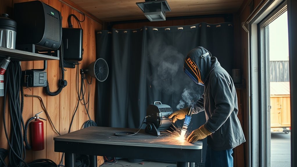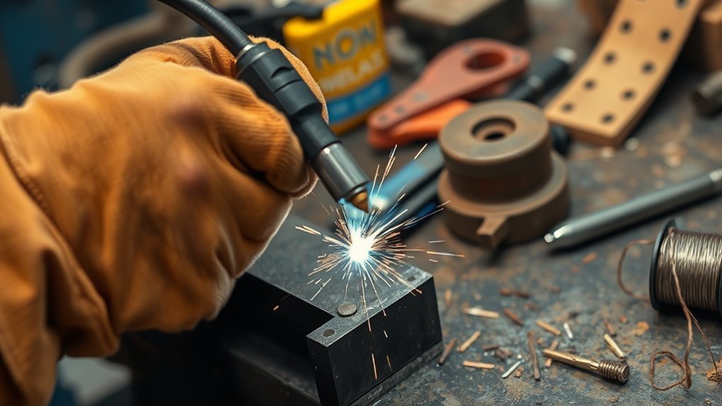
A weld that will not stick can mean several different things. A stick electrode may freeze to the work, a MIG bead may sit on top without fusing, a tack may snap off, or the arc may keep going out. The fastest fix is to identify the exact symptom, check the setup in a safe order, and change only one variable at a time.
Quick Answer
If a weld sits on top, breaks off, or a stick electrode keeps freezing, clean the joint and work-clamp area first. Then verify polarity, consumable type, machine-chart settings, arc length, travel speed, fit-up, and shielding gas. Change one variable at a time and test each adjustment on matching scrap.
Key Takeaways
- “Not sticking” may mean electrode sticking, an unstable arc, lack of fusion, a broken tack, or MIG wire burnback.
- Clean the joint and the work-clamp contact point before changing machine settings.
- Use the polarity, gas, wire, electrode, and starting settings specified by the machine and consumable manufacturers.
- Both excessive and insufficient travel speed can produce weak fusion.
- Never judge a load-bearing or safety-critical weld by appearance alone.
At a Glance
| Time Required | About 15–45 minutes for basic inspection, cleaning, setup checks, and a scrap-metal test |
| Difficulty | Beginner to intermediate; critical joints require a qualified welder or inspector |
| Tools Needed | Correct PPE, machine manual, wire brush or grinder, clamps, clean scrap metal, and process-specific consumables |
| Cost | Often $0–$30 for cleaning supplies, tips, nozzles, or fresh consumables; more if cables, regulators, liners, or machine parts need repair |
Warning: Wear a welding helmet with the correct lens shade, safety glasses, flame-resistant clothing, suitable gloves, and hearing protection when needed. Control fumes with suitable ventilation or local exhaust. Keep sparks away from combustible material, inspect cables for damage, and never weld a tank, drum, pipe, or other container that may have held a flammable, toxic, or reactive substance unless it has been prepared and declared safe by a qualified person. Follow OSHA welding-safety guidance and your equipment manual.
What’s in This Article
- Identify What “Not Sticking” Means
- Common Causes of Weld Adhesion Problems
- Improve Weld Adhesion and Penetration
- Set the Right Power for Stronger Welds
- Prepare Metal Surfaces for Better Weld Quality
- Control Environmental Factors While Welding
- Make Stronger Tack Welds
- Troubleshoot Common Weld Quality Issues
- Verify That the Fix Worked
- Get Help and Improve Your Welding Skills
- Frequently Asked Questions
- Conclusion
- Sources
Identify What “Not Sticking” Means
Before changing the heat, identify what is actually failing. Several different welding problems are often described as a weld that “will not stick.”
| Symptom | What It Usually Means | First Checks |
|---|---|---|
| Stick electrode freezes to the work | The amperage may be low, the arc may be too short, or the electrical connection may be poor. | Electrode range, polarity, clean work-clamp contact, arc length, and cable condition |
| Bead sits high and peels or breaks away | The weld may have incomplete fusion caused by contamination, weak heat at the joint, poor angle, poor fit-up, or incorrect travel speed. | Surface preparation, joint access, settings, travel angle, arc length, and speed |
| Tack weld snaps during handling | The tack may be too small, cold, contaminated, cracked, or placed over a large gap. | Fit-up, clean metal, tack size, penetration into both pieces, and restraint |
| Arc starts and repeatedly goes out | Input power, work connection, consumable condition, arc length, or machine settings may be unstable. | Outlet and extension-cord suitability, leads, clamp, settings, and consumable condition |
| MIG wire fuses to the contact tip | Wire feeding may have stopped while the arc remained active. | Contact tip, liner, drive-roll tension, spool drag, gun-cable bends, wire speed, and stickout |
This distinction matters because adding more heat will not fix every problem. A gas leak, wrong polarity, worn contact tip, contaminated tungsten, blocked liner, or loose work clamp must be corrected at its source.
Common Causes of Weld Adhesion Problems
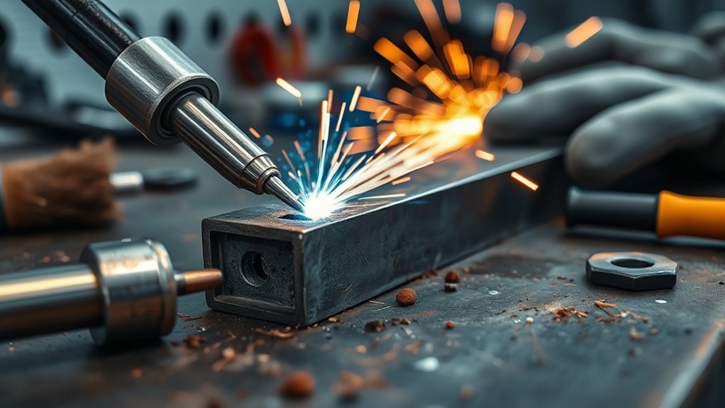
When your weld is not sticking, start with the basics. Oil, rust, paint, moisture, heavy mill scale, oxide, and dirt can keep the weld pool from fusing with sound base metal. A dirty work-clamp contact point can also produce an unstable arc even when the joint itself looks clean.
Incorrect settings are another common cause. Too little usable heat at the joint can leave a raised bead with poor toe fusion. Excessive heat can cause burn-through, undercut, distortion, or an uncontrollable puddle. The correct adjustment depends on the process, material, joint design, consumable, and welding position.
Travel technique matters as much as the number on the machine. Moving too fast can create a narrow bead, underfill, and weak penetration. Moving too slowly can pile filler metal onto the surface and create cold lap because heat remains in the puddle instead of reaching the leading edges. Miller’s stick-welding technique guide describes current, arc length, angle, manipulation, and travel speed as connected variables.
Drafts, leaks, condensation, and contamination can also weaken gas-shielded welds. Proper shielding gas flow helps, but turning the gas up without checking the manual is not always the answer. Excess flow can create turbulence and draw surrounding air into the shielding envelope.
Do Not Overlook the Electrical Circuit
The welding circuit must be complete and stable. Place the work clamp on clean, solid metal as close to the weld area as practical. Do not clamp over paint, rust, loose scale, an insulated bearing, or a poor mechanical connection. Inspect the leads, connectors, electrode holder, gun, and machine receptacle for heat damage or loose parts before welding.
Note: The work clamp completes the welding circuit. It is often called a ground clamp, but it does not replace the equipment-grounding and electrical-safety requirements in the machine manual.
Improve Weld Adhesion and Penetration
Use the following order instead of changing several controls at once.
- Stop and make the area safe. Remove combustible material, provide suitable fume control, put on complete PPE, and make sure the workpiece is stable.
- Identify the base metal and coating. Do not weld unknown plated, painted, galvanized, heat-treated, or alloy material until you understand the fume and procedure requirements.
- Clean the joint and clamp location. Remove contamination far enough from the joint that it cannot melt, burn, or flow into the puddle.
- Check fit-up. Confirm that the root opening, bevel, alignment, and access match the joint and procedure.
- Verify the consumable. Check wire or electrode classification, diameter, polarity, gas requirement, condition, and recommended operating range.
- Start with the machine chart or manual. Use the listed starting settings for the material thickness, wire or electrode, gas, and process.
- Watch the puddle. Keep the arc on the leading edge and confirm that the molten metal wets into both sides of the joint.
- Change one variable. Adjust in small steps and make another bead on matching scrap.
- Keep a steady arc length so the heat remains focused on the joint.
- Choose the correct electrode, wire, tungsten, and filler size for the material.
- Use an angle that directs the arc into both pieces instead of only one side.
- Slow down when excessive speed is leaving a narrow, underfilled bead.
- Speed up or reduce deposition when the puddle is rolling ahead and the bead is piling onto the surface.
Pro Tip: Test on scrap made from the same material and thickness, in the same position, with the same joint shape. A bead-on-plate test may not reveal a problem that appears only in a fillet or groove joint.
A stable arc and attractive bead do not guarantee fusion. Watch whether the puddle ties into both joint edges, then verify the result with an appropriate test.
Products Worth Considering

🧲 Sticks to Toolboxes & Welders – Heavy-duty magnetic welding chart adheres to metal surfaces like your welding table, toolbox, or wall for instant reference while working.

Package Including 10pcs x 0.035" Contact Tip, 2pcs x Gas Nozzle, 2pcs x Gas Diffuser.

COMPATIBILITY: Designed for Lincoln Magnum 100L (K530 series) and Tweco Mini/#1 welding torches. This kit is also a direct fit for YESWELDER FLUX-135PRO Old Version/MIG-140DS PRO/YWM-160/MIG-165DS PRO/MIG-185DS PRO/MIG-205DS PRO/MIG-250PRO/MCT-520.
Set the Right Power for Stronger Welds
Good weld quality depends on surface preparation, joint access, technique, and the correct machine setup. Avoid treating voltage and amperage as interchangeable controls. Miller explains that stick and TIG normally use constant-current output, while MIG and flux-core normally use constant-voltage output. Follow the chart inside the machine, the owner’s manual, and the consumable data before fine-tuning the arc.
| Process | Check First | When the Weld Looks Cold |
|---|---|---|
| MIG/GMAW | Wire type and diameter, shielding gas, polarity, voltage, wire-feed speed, contact-tip-to-work distance, and machine chart | Confirm clean metal and proper travel first. Then adjust voltage and wire-feed speed together in small steps within the recommended range. |
| Flux-core/FCAW | Whether the wire is self-shielded or gas-shielded, the exact required polarity, wire diameter, drive rolls, and gas if required | Correct polarity before changing heat. Use the wire manufacturer’s voltage and wire-feed range, and remove slag between passes. |
| Stick/SMAW | Electrode type, diameter, polarity, storage condition, amperage range, arc length, and work connection | If the rod sticks and the arc stutters, raise amperage in small steps within the electrode range and avoid pressing the rod into the puddle. |
| TIG/GTAW | Polarity or AC mode, amperage control, tungsten type and condition, gas, cup, filler, torch distance, and joint fit-up | Shorten an excessive arc, direct the arc into the root, clean or regrind contaminated tungsten, and increase current only within the procedure and machine limits. |
Products Worth Considering
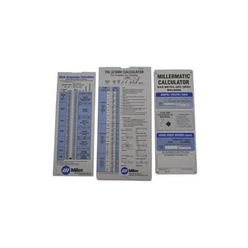
Comprehensive 3‑in‑1 reference pack covers MIG, TIG and Stick welding parameters—ideal for welders who work across multiple processes

Used Book in Good Condition

[INDUSTRIAL GRADE MATERIAL] - Forged from cast iron and finished with chrome plating, this 3-spoke handwheel ensures lasting performance and resistance to wear, oil, and high temperatures, for intense machinery operations.
Adjust MIG Voltage and Wire Feed Together
With MIG welding, voltage affects arc length and bead profile, while wire-feed speed strongly affects welding current and deposition. If the wire repeatedly stubs into the work, the wire feed may be too high for the voltage, the gun may be too close, or the arc may be unstable. If the arc burns back toward the tip, the wire feed may be interrupted or too low for the voltage.
Start with the chart for the installed wire, gas, and metal thickness. Check the correct wire type, contact-tip size, drive rolls, spool tension, and gun liner before blaming the power source.
Correct Stick Amperage and Arc Length
For stick welding, the electrode manufacturer normally lists an amperage range. If amperage is too low, the electrode may stick when the arc is struck or the arc may repeatedly go out. A very short arc also increases the chance of freezing the rod to the work. Miller recommends making small amperage changes while staying within the electrode’s operating range.
Excessive amperage can create a puddle that is difficult to control, increase spatter, damage the electrode coating, and cause undercut. More current is not automatically a stronger weld.
Verify Polarity Before Fine-Tuning
Polarity affects arc behavior, penetration, deposition, and shielding. Solid-wire MIG commonly uses a different polarity from many self-shielded flux-core wires, and stick-electrode requirements vary by classification. Do not rely on a general rule. Read the wire or electrode label and confirm the lead connections.
Understanding lack of penetration can help you recognize a cold-looking bead, but the machine manual and consumable specifications should control the setup.
Prepare Metal Surfaces for Better Weld Quality
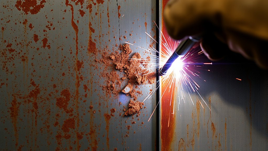
Surface preparation has a major effect on weld quality. Oil, rust, paint, dust, oxide, moisture, and heavy mill scale can contaminate the puddle or prevent the arc from reaching sound base metal. Clean metal also makes it easier to see whether the bead is wetting into the joint.
- Grind or clean both joint faces to sound metal when scale or coating blocks the arc.
- Clean a separate bare-metal area for the work clamp.
- Use a wire wheel, flap disc, grinder, scraper, or approved cleaner suited to the base metal.
- Allow cleaned parts to dry completely before welding.
- Clamp the pieces so the fit-up matches the joint design.
- Keep cleaning residue, loose abrasive, and grinding dust out of the joint.
Mild Steel
Remove oil, paint, heavy rust, and loose or heavy mill scale around the joint. Some electrodes tolerate less-than-perfect surfaces, but clean metal improves arc stability and reduces the chance of inclusions and lack of fusion. Good proper cleaning is especially important for short tacks and low-powered machines.
Aluminum
Remove grease and contamination with a suitable cleaner, allow it to evaporate, and remove the oxide with a clean stainless-steel brush reserved for aluminum. Miller notes that aluminum oxide must be removed and that a stainless-steel brush helps avoid contamination from an ordinary steel brush.
Stainless Steel
Use tools reserved for stainless steel so carbon-steel particles do not become embedded in the surface. Follow the filler-metal, shielding-gas, purge, and heat-input requirements for the grade and service.
Painted, Plated, and Galvanized Metal
Warning: Do not assume an unknown coating is safe to grind, heat, or weld. Galvanized, lead-, cadmium-, chromium-, and other coated or alloyed metals can produce hazardous fumes. Identify the material, review its safety information, remove coatings only by an appropriate method, and use the ventilation, respiratory protection, and work controls required by OSHA welding requirements and the applicable procedure.
Keep welding arcs and heat away from chlorinated-solvent vapors, degreasing operations, and other reactive cleaning chemicals. Use only a cleaning product and method approved for the metal and welding operation.
Control Environmental Factors While Welding
Environmental factors can change weld quality quickly. Wind and drafts can disturb shielding gas. Moisture can condense on cold metal or consumables. Dirt can block the nozzle or contaminate the puddle. A clean, dry, controlled workspace makes troubleshooting much easier.
Suitable ventilation in the work area helps control fume exposure, but an ordinary fan should not blow across a gas-shielded arc. Position extraction so it captures fumes without stripping shielding gas from the weld.
Wind and Draft Effects
Moving air can push shielding gas away from the puddle and allow the atmosphere to contaminate the weld. Miller lists wind, improper settings, and equipment leaks among the causes of poor shielding and porosity in MIG welding.
- Use a suitable welding screen or wind barrier.
- Turn off fans that blow directly across the joint.
- Check hoses, fittings, the regulator, gun connection, diffuser, and O-rings for leaks or damage.
- Remove spatter from the nozzle and confirm that the diffuser ports are open.
- Set gas flow according to the equipment and consumable guidance.
- Do not assume more flow is better; excessive flow can create turbulence.
- Keep the nozzle close enough to cover the molten pool without contacting it.
Temperature Fluctuation Impact
Cold metal can pull heat away from a small weld pool, but moisture is often the more immediate concern. ESAB notes that condensation can form when the metal is at or below the local dew point, introducing hydrogen and increasing porosity risk.
Move cold material into the work area early enough to warm and dry when practical. Keep the joint and consumables dry. Preheat only when the drawing, welding procedure specification, manufacturer, engineer, or qualified welding guidance calls for it. Do not guess at a preheat temperature, especially on high-strength, heat-treated, cast, or unknown alloy material.
Workspace Cleanliness Importance
A clean workspace helps prevent contamination and poor electrical contact. Grinding dust, oil, water, loose scale, and spatter inside a gas nozzle can all create trouble.
- Check the joint for mill scale, foreign material, and moisture.
- Clean clamps, fixtures, and electrical contact points.
- Clamp materials tightly enough to hold the required fit-up.
- Keep gas nozzles, cups, collets, contact tips, and diffusers clean.
- Store wire, electrodes, filler rods, and tungsten where they remain clean and dry.
Make Stronger Tack Welds
Strong tack welds need clean metal, close fit-up, stable restraint, and enough fusion into both pieces. Start the tack where the joint fits tightly. Direct the arc into both sides and watch for the puddle to wet into each edge.
A tack should be large enough to hold the assembly during handling and welding, but it should not introduce unnecessary heat or interfere with the final weld. The correct tack size, spacing, sequence, and removal requirements depend on the joint and procedure.
The maximum fillet weld size and required final weld size must follow the drawing, design, code, or welding procedure. A larger weld is not automatically stronger and can increase distortion or residual stress.
Proper Heat Settings
Proper heat settings help a tack fuse before the joint absorbs or pulls away too much heat. Do not automatically use a higher setting than the final weld. Start with the approved or chart-based setting for the process and material, then verify the tack on scrap.
- Use enough usable heat at the joint to fuse both pieces.
- Correct low stick-welding amperage if the rod freezes or the arc stutters.
- For MIG or flux-core, tune voltage and wire feed within the recommended range.
- Use short, controlled tacks to limit distortion.
- Clean cracked or defective tacks out before the final weld.
Clean Surface Preparation
Rust, scale, oil, coating, dirt, moisture, and large gaps can weaken a tack. Use the table below to match common preparation problems with safer corrections.
| Condition | Correction | Possible Effect |
|---|---|---|
| Rust | Remove with a suitable wire wheel, abrasive, or grinder | Porosity, unstable arc, and poor fusion |
| Heavy mill scale | Grind the joint faces to sound metal when required | Inclusions and incomplete fusion |
| Oil or dirt | Use a suitable cleaning method and let the part dry | Porosity and contamination |
| Large or uneven gap | Correct the fit-up with proper cutting, preparation, or clamping | Burn-through, shrinkage, and weak or undersized tacks |
| Cold or damp material | Warm and dry naturally; use specified preheat only when required | Porosity, hydrogen problems, or weak starts |
Effective Tack Techniques
Strong tack welds depend on clean surfaces and steady technique. Use short, controlled welds and give each tack enough time to fuse both pieces. Avoid long, overheated tacks that pull thin panels out of shape.
- Place tacks where both pieces fit correctly.
- Distribute tacks to control movement and distortion.
- Do not bridge a poor fit-up with a surface-only blob.
- Inspect each tack for cracks, porosity, and incomplete tie-in.
- Grind out defective tacks instead of burying them under the final weld.
Troubleshoot Common Weld Quality Issues
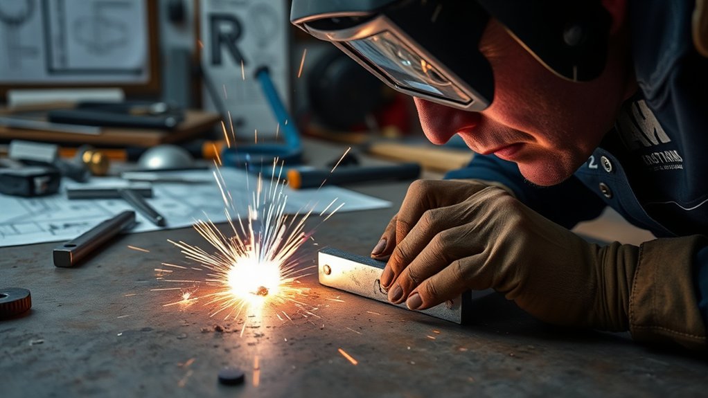
When troubleshooting weld quality, check the setup before blaming the machine. Start with clean metal, the correct polarity, a sound work connection, suitable input power, and dry consumables. Then check settings, wire delivery, gas coverage, arc length, angle, fit-up, and travel speed.
Use the correct amperage range for the specific electrode. Keep the arc controlled because an unstable or excessively long arc can increase spatter and porosity. Watch the leading edge of the puddle instead of only the finished bead.
| Issue | Likely Causes | What to Do |
|---|---|---|
| Lack of fusion | Contamination, poor joint access, incorrect settings, wrong angle, excessive speed, very slow cold-lapping travel, or an arc directed away from the joint | Clean and prepare the joint, verify the process chart, direct the arc into both edges, and adjust travel while watching the puddle. |
| Porosity | Oil, paint, moisture, wrong gas, wind, a leak, blocked nozzle, excessive gas turbulence, long arc, or damp consumables | Remove contamination, check the full gas path, shield the arc, use the specified gas flow, shorten an excessive arc, and use properly stored consumables. |
| Weak or broken tack | Poor fit-up, undersized tack, surface contamination, crack, one-sided fusion, or movement before cooling | Correct the fit, clean the area, fuse both pieces, place suitable tacks, and remove cracked tacks. |
| Stick electrode keeps sticking | Low amperage, arc too short, wrong polarity, poor work connection, wrong electrode, or damp/damaged coating | Check the rod label, polarity, clamp, and cables. Raise amperage slightly within the listed range and maintain a controlled arc gap. |
| MIG wire burns back to the tip | Interrupted wire feed, excessive spool drag, kinked liner, worn tip, cable bend, excess drive pressure, low wire speed, or excessive voltage | Replace the damaged tip, clear the liner, straighten the gun cable, set drive and spool tension correctly, and return to the chart settings. |
| Burn-through | Excess heat, slow travel, large gap, thin edge, poor joint support, or the wrong process setting | Reduce heat within the approved range, correct the fit-up, increase travel as needed, use short welds, or use suitable backing where the procedure allows. |
| TIG filler balls up or will not flow | The base metal is not forming a proper puddle, oxide remains, the arc is too long, filler is being heated outside the shield, or tungsten is contaminated | Clean the metal and filler, establish the puddle first, shorten the arc, keep filler in the gas envelope, and regrind contaminated tungsten. |
| Arc is unstable | Loose clamp, damaged lead, poor input supply, wrong polarity, dirty contact point, incorrect consumable, or machine protection cycling | Stop, disconnect power as directed by the manual, inspect the circuit, correct the supply or lead problem, and allow the machine to cool if it exceeded its duty cycle. |
Note: Change one setting at a time. Record the material, thickness, joint, process, polarity, consumable, gas, voltage, amperage, wire-feed speed, and result so you can repeat a successful setup.
Verify That the Fix Worked
A better-looking bead is encouraging, but appearance alone cannot prove penetration or internal fusion. Start with a careful visual check:
- The bead toes blend into both sides rather than curling over an unfused edge.
- The bead follows the joint and does not wander onto only one piece.
- There are no visible cracks, open pores, trapped slag, severe undercut, or missed areas.
- The profile is reasonably consistent for the joint and procedure.
- The tack or weld does not separate under the handling it was designed to withstand.
For practice, make a separate coupon with the same setup. A suitable bend, break, cut-and-etch, or fillet-break test can expose internal fusion, but use a recognized test method and proper eye, face, hand, and impact protection. Do not strike, bend, or destructively test the finished part unless the approved inspection plan calls for it.
Warning: Do not rely on a garage test for a structural, vehicle-safety, lifting, pressure-containing, rollover-protection, overhead, or life-safety joint. Use the required welding procedure, qualified personnel, specified filler metal, and appropriate inspection or nondestructive testing.
Get Help and Improve Your Welding Skills
You can improve faster when an experienced welder or instructor can inspect your setup, puddle control, travel angle, bead, and test coupon. A short review often reveals a poor viewing position, excessive arc length, wrong polarity, or fit-up problem that is difficult to diagnose alone.
Good feedback can help you correct small setup and technique errors before they become habits.
- Read the machine manual and the technical data for the exact wire or electrode.
- Use training material from established welding manufacturers and recognized trade programs.
- Ask a qualified welder or instructor to review your scrap test.
- Attend a community-college, apprenticeship, manufacturer, or certified training course when available.
- Use forums and community groups for ideas, but verify safety and procedure advice against authoritative sources.
- Compare sectioned or broken practice coupons, not only bead appearance.
- Read about underwater welding techniques separately if you are exploring advanced welding careers and their additional training requirements.
Practice still matters most. Keep notes on your settings, material, thickness, joint, position, and results. That record gives you a reliable starting point the next time a weld will not stick.
Frequently Asked Questions
Why do my welds not hold?
A weld may fail because the joint is contaminated, the arc is not reaching sound metal, the polarity or consumable is wrong, the settings do not match the process, the travel technique is poor, or the fit-up blocks root access. Clean the joint and clamp area, return to the manufacturer’s starting setup, and test one adjustment at a time on matching scrap.
Why does my stick welding rod keep sticking?
The amperage may be too low, the arc may be too short, or the work connection may be poor. Confirm the electrode type, diameter, polarity, and listed amperage range. Clean the clamp contact, raise current in small steps within that range, and avoid pushing the rod into the puddle.
Why does MIG wire stick to the contact tip?
Wire can burn back into the tip when feeding stops or becomes too slow while the arc remains active. Check the tip size, liner, drive rolls, spool tension, gun-cable bends, wire condition, stickout, voltage, and wire-feed speed. Replace a damaged tip and return to the machine-chart settings before fine-tuning.
Should you coat welding rods with WD-40?
No. Oil can contaminate the weld and may damage or interfere with the electrode coating. Keep electrodes clean and dry in the storage conditions specified by the manufacturer. Follow product-specific holding or redrying instructions instead of spraying rods with oil or placing them in an improvised household oven.
What is the golden rule in welding?
There is no single official golden rule for every welding process. A reliable working rule is to protect yourself, identify the material, follow the approved procedure and manufacturer instructions, clean the joint, verify the setup, and never assume a good-looking bead is structurally sound.
Can welding trigger migraines or headaches?
Intense arc light, fumes, heat, noise, stress, and dehydration may contribute to headaches or trigger symptoms in a sensitive person. Use the correct helmet shade, safety glasses, ventilation, hearing protection, hydration, and breaks. Stop welding and seek medical advice for severe, recurring, sudden, or vision-related symptoms.
How do you know if a weld has poor penetration?
A high bead, rolled-over toes, weak tacks, incomplete root fill, or a bead that separates during a proper coupon test can suggest poor penetration or fusion. Visual appearance cannot confirm the inside of a weld. Critical joints require the specified destructive test, nondestructive examination, or qualified inspection.
Conclusion
A weld that will not stick usually points to one of four areas: contamination, an unstable electrical or gas setup, incorrect process settings, or technique that keeps the arc from reaching the joint. Identify the symptom first, clean the joint and work connection, verify the polarity and consumable, return to the manufacturer’s starting settings, and test one change at a time.
Do not solve every problem by adding heat. MIG, flux-core, stick, and TIG respond differently, and both travel extremes can reduce fusion. Use scrap coupons to confirm your correction, and turn structural, pressure-containing, lifting, vehicle-safety, or other critical work over to qualified personnel and the required inspection process.
Sources
- OSHA — Welding, Cutting, and Brazing: Hazards and Solutions — welding fumes, ultraviolet radiation, burns, eye injury, electrical shock, and protective controls.
- OSHA — 29 CFR 1910.252 General Welding Requirements — ventilation, coated-metal hazards, fire prevention, and welding safety requirements.
- Miller Electric — Five Steps to Improving Your Stick Welding Technique — cleaning, work-clamp contact, current, arc length, angle, and travel speed.
- Miller Electric — Common MIG Weld Defects — porosity, shielding-gas loss, lack of fusion, burn-through, and aluminum preparation.
- Miller Electric — Common TIG Welding Problems — root fusion, fit-up, torch distance, filler technique, and crater control.
- ESAB — Impact of Atmospheric Conditions on Weld Quality — moisture, condensation, dew point, hydrogen, and porosity.