
When a welder keeps tripping the breaker, the trip is a warning—not an obstacle to bypass. The circuit may be overloaded, the extension cord may be causing voltage drop, a connection may be damaged, or the welder may have an internal fault. The safest diagnosis starts with the machine’s exact input requirements and the type of protective device that opened.
Quick Answer
A welder usually trips a breaker because the circuit is overloaded, the supply voltage drops, a cord or connection is damaged, or the machine has an electrical fault. Stop after another trip, check the exact owner’s-manual requirements, remove other loads and extension cords, and have persistent trips inspected professionally.
Key Takeaways
- Read the welder’s input-voltage, input-current, duty-cycle, and circuit-protection requirements before blaming the breaker.
- Identify whether a standard breaker, GFCI, or AFCI opened because each device responds to a different electrical condition.
- Use a dedicated circuit when the manufacturer requires or recommends one, and do not size a welder circuit from a generic wire chart alone.
- Remove damaged or hot cords, plugs, and receptacles from service immediately.
- Do not repeatedly reset the breaker, install a larger breaker, defeat a grounding pin, or bypass required GFCI or AFCI protection.
- Call an electrician for building-circuit problems and an authorized service center when the correctly supplied welder still trips the circuit.
At a Glance
| Time Required | 10–20 minutes for safe external checks; professional diagnosis may take longer |
| Difficulty | Basic for visual checks; advanced electrical testing requires a qualified person |
| Tools Needed | Welder owner’s manual, flashlight, circuit label information, and the model or serial number |
| Cost | Usually $0 for basic checks; circuit repair, a dedicated outlet, or machine service varies by diagnosis |
Why a Welder Trips the Breaker
A circuit breaker opens when it detects a condition it is designed to interrupt. With a standard thermal-magnetic breaker, that condition is commonly an overload or short circuit. A GFCI responds to current leaking away from the intended circuit path, while an AFCI responds to electrical patterns associated with arcing.
That distinction matters because a welder can be below the circuit’s normal amp rating and still trip a GFCI or AFCI. Do not assume every trip means the breaker is too small.
Arc welders can also draw a brief inrush when they power up or establish an arc. The owner’s manual may specify particular overcurrent protection that accommodates the machine’s normal operating characteristics. Never change the breaker size or type based only on trial and error.
Warning: Do not tape a breaker on, hold its handle in place, replace it with a larger device, or defeat GFCI or AFCI protection. A breaker that opens again after one controlled check needs professional diagnosis.
What the Trip Timing Can Tell You
| When It Trips | Possible Causes | Next Step |
|---|---|---|
| As soon as the welder is plugged in | Damaged plug or cord, wiring fault, moisture, ground fault, or internal input fault | Unplug the machine and stop. Do not try another circuit until the equipment has been inspected. |
| When the power switch is turned on | Normal inrush exceeding incorrect protection, shorted input component, or circuit fault | Confirm the manual’s circuit specification. Persistent trips require an electrician or service technician. |
| When the arc starts | Shared-circuit overload, voltage drop, undersized extension cord, incorrect supply, or machine fault under load | Remove other loads and any extension cord, then compare the circuit with the owner’s manual. |
| After several minutes | Sustained overload, excessive duty cycle, poor connection, hot receptacle, long cord, or weak breaker | Allow the equipment to cool, inspect accessible parts, and arrange testing before continued use. |
| Only the GFCI or AFCI indicator appears | Leakage current, damaged insulation, moisture, arcing connection, wiring issue, or incompatible/faulty equipment | Do not bypass the device. Have the circuit and welder evaluated. |
Read the Welder’s Input Label First
The welding amperage shown on the front control is output current. It does not directly tell you what branch circuit the machine needs. Circuit sizing starts with the input information on the rating plate and in the electrical service section of the owner’s manual.
Look for these values:
- Input voltage: Common portable machines use 120 volts, 240 volts, or either voltage with the correct adapter and setup.
- Phase: Most home-shop welders use single-phase power. Industrial machines may require three-phase power.
- Input current: This shows how much current the machine draws under stated operating conditions.
- I1max: The rated maximum supply current shown on many welding power sources.
- I1eff: The maximum effective supply current, which accounts for the machine’s operating cycle under the applicable rating method.
- Duty cycle: The percentage of a specified test period that the welder can operate at a stated output before it must cool.
- Recommended protection: The manufacturer may list a maximum fuse or breaker rating and may distinguish time-delay protection from normal protection.
- Minimum conductors and maximum run length: These values may appear in an electrical service guide and are specific to the installation conditions stated in the manual.
Use the exact manual for your model and serial-number range. The Miller owner’s-manual search, for example, asks for the unit’s model or serial number so the instructions match the actual machine.
The correct circuit starts with the welder’s electrical service guide—not a generic breaker-and-wire chart.
A Real 120-Volt Example
Lincoln Electric’s Handy MIG manual specifies 120-volt input, 20 input amps at rated output, a 20-amp fuse or breaker, and a three-conductor #12 AWG or larger extension cord up to 50 feet.
That example explains why people often associate compact 120-volt welders with 20-amp circuits. It does not establish the correct circuit for a different machine. Another welder may list different protection, conductor, receptacle, or cord requirements.
Dual-Voltage Welders
A dual-voltage welder can have very different input-current requirements at 120 and 240 volts. Running the machine on 240 volts commonly allows more output with lower line current for a given power level, but only when the machine, plug, adapter, branch circuit, and manufacturer instructions support that connection.
Do not make a homemade adapter that combines circuits, changes plug geometry, removes a grounding pin, or connects a 120-volt machine to 240 volts. Use only the approved input cord and adapter arrangement described by the manufacturer.
Common Reasons a Welder Keeps Tripping
Products Worth Considering

50FT CORD LENGTH: Safely extend your power up to 50 ft away, which may be combined with your existing welder cords and adapters, protecting you and others from hazardous welder spark.

SAFE & RELIABLE: This professional 220V extension cord delivers stable performance. The 50ft length provides a convenient distance from the power source. Built with 8AWG wire, rated for 40 Amp, 3 conductors, and equipped with NEMA 6-50P to 6-50R connectors. ETL listed and designed for dependable power transmission in various applications.
Shared or Overloaded Circuit
A shared circuit may power lights, grinders, heaters, chargers, fans, or an air compressor in addition to the welder. The combined load can open the breaker even when each device works normally by itself.
A welder may also run at a low setting but trip the breaker when output or arc time increases. Higher welding demand generally requires more input power, and a sustained load can heat the breaker until its thermal element opens.
Use a dedicated circuit when the manufacturer requires or recommends one. A dedicated circuit also removes other shop loads from the diagnosis.
Wrong Supply Circuit or Protection
A breaker may be smaller than the manufacturer’s recommendation, but the solution is not simply to install a larger one. The entire circuit—including the conductors, disconnect, receptacle, plug, panel capacity, grounding path, installation method, and local code—must support the manufacturer’s electrical service requirements.
Some welder manuals specify time-delay fuses or breaker time-current characteristics that tolerate normal inrush. Leave that selection to the manufacturer’s instructions and a qualified installer.
Extension-Cord Voltage Drop
A long or light-duty extension cord adds resistance. Under load, that resistance can lower the voltage reaching the welder and create heat in the cord, plug, or connectors. The result may be weak output, erratic operation, or a breaker trip.
Follow the exact cord gauge and maximum length in the owner’s manual. The cord must have:
- A current and voltage rating suitable for the welder
- An intact equipment-grounding conductor and ground pin
- Connectors that match without adapters or forced insertion
- An outdoor or wet-location rating when the environment requires it
- No cuts, crushed areas, loose blades, discoloration, or repaired insulation
Electrical Safety Foundation International guidance states that extension cords are temporary equipment, should not be overloaded, and should never be used when hot or damaged.
Pro Tip: For diagnosis, connect the welder directly to the correct receptacle whenever the manufacturer permits it. Removing the extension cord eliminates one major source of voltage drop and connection resistance.
Loose, Worn, or Damaged Connections
Loose terminals and worn receptacle contacts can produce resistance and concentrated heat. Warning signs include:
- A plug that fits loosely or falls out
- Brown or black marks on a receptacle or plug
- Melted or distorted plastic
- Buzzing, crackling, or a hot electrical smell
- A cord, plug, receptacle, or breaker area that becomes warm
- Intermittent power when the cord moves
Unplug the welder and remove damaged equipment from service. Do not open the service panel, tighten energized terminals, or remove the welder cover unless you are qualified and following the manufacturer’s service procedure.
GFCI or AFCI Operation
A GFCI compares current leaving and returning through the intended conductors. It opens when it detects a leakage-current imbalance. An AFCI looks for electrical signatures associated with arcing. Combination breakers may provide more than one form of protection.
Check the breaker or receptacle label and any diagnostic indicator. A GFCI or AFCI trip may point to moisture, damaged insulation, a loose connection, leakage inside the welder, or a branch-circuit problem rather than excessive total amperage.
Do not replace a GFCI or AFCI with an ordinary breaker merely because the welder trips it. Have the compatibility and fault condition evaluated under the code adopted in your area.
Internal Welder Fault
If the welder trips a correctly installed circuit while directly connected and no other loads are present, the machine may have an internal problem. Possible faults include a damaged input cord, failed power switch, shorted rectifier or power component, contaminated circuit board, fan fault, or damaged internal insulation.
Inverter welders can retain dangerous voltage after they are unplugged. Keep covers in place and use an authorized service technician unless the manufacturer specifically authorizes the procedure and you are qualified to perform it.
General arc-welding machine troubleshooting can help identify performance symptoms, but a supply breaker that continues to open calls for electrical testing rather than repeated welding attempts.
Weak or Damaged Breaker
A breaker can become damaged or develop poor connections, but it should not be treated as the first or only suspect. An electrician can verify the circuit load, conductor condition, terminations, voltage under load, breaker temperature, and whether the device is appropriate for the panel and application.
Never replace a breaker with a different brand, style, amp rating, or trip characteristic unless it is listed for that panel and selected for the complete installation.
Safe Step-by-Step Troubleshooting
Use the following process only for external checks that do not expose energized parts. Stop immediately when you find heat, damage, moisture, smoke, or a burning smell.
- Turn off and unplug the welder. Let hot cords or connectors cool without touching exposed or melted parts.
- Identify what tripped. Determine whether it was a standard breaker, GFCI receptacle, GFCI breaker, AFCI breaker, or combination device. Note any indicator light or code.
- Inspect accessible parts. Check the input cord, plug, adapter, extension cord, and receptacle face for cuts, loose blades, missing ground pins, moisture, discoloration, or melted plastic.
- Read the exact manual. Confirm input voltage, phase, recommended branch circuit, breaker or fuse information, extension-cord limits, and any requirements tied to rated output or duty cycle.
- Remove other circuit loads. Unplug heaters, compressors, grinders, lights, chargers, and other equipment that may share the branch circuit.
- Remove the extension cord. Connect directly to the correct receptacle if the manufacturer permits it and the plug fits normally.
- Make one controlled test only. Reset the protective device after the cause has been reviewed and the circuit appears safe. Start at a moderate setting within the machine’s instructions. Do not continue if it trips again.
- Record the pattern. Note whether the trip occurred at plug-in, power-on, arc strike, high output, or after a certain number of minutes. This information helps the electrician or service technician.
- Escalate the problem. Call an electrician for circuit, receptacle, panel, GFCI, AFCI, breaker, grounding, or voltage concerns. Contact an authorized welder service center when the supply is verified but the machine still trips.
Note: Lowering the welding setting may temporarily reduce input demand, but it does not repair an undersized circuit, damaged connection, leakage fault, or defective welder.
Products Worth Considering
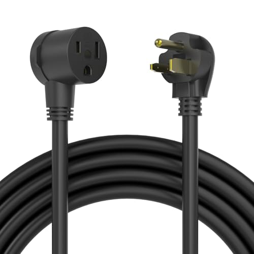
50FT CORD LENGTH: Safely extend your power up to 50 ft away, which may be combined with your existing welder cords and adapters, protecting you and others from hazardous...
How Breaker, Wire, and Receptacle Sizing Work
The breaker, conductors, receptacle, disconnect, plug, panel, and welder form one system. Each part must be selected under the manufacturer’s instructions and the electrical code adopted by the local authority.
General household rules such as “12 AWG for 20 amps” are not enough to design every dedicated welder circuit. Article 630 of the National Electrical Code contains provisions for electric welders, including duty-cycle and overcurrent considerations. A manufacturer’s electrical service guide may therefore show combinations that differ from a generic continuous-load chart.
For example, some Miller electrical service guides state that, in a qualifying dedicated-circuit installation, the NEC permits the receptacle or conductor rating to be less than the circuit-protection-device rating. The same guides require all circuit components to be physically compatible and direct the installer to the applicable NEC sections.
Warning: This special welder-circuit allowance is not permission to place a larger breaker on existing wiring. It requires a complete calculation and installation under the applicable code, equipment listing, manufacturer instructions, and local inspection rules.
Circuit Items to Verify
| Circuit Item | What Must Be Verified |
|---|---|
| Supply voltage and phase | Must match the rating plate and approved input configuration. |
| Breaker or fuse | Must be listed for the panel and match the manufacturer’s service guide and applicable code. |
| Supply conductors | Material, insulation, temperature rating, installation method, length, terminations, and duty-cycle calculations must be considered. |
| Receptacle and plug | Must be mechanically compatible, properly grounded, undamaged, and approved for the installation. |
| Dedicated circuit | Often recommended for stable operation and may be required by the electrical service instructions. |
| Panel capacity | The service and panel must have capacity for the calculated added load. |
| Local code | The adopted NEC edition and local amendments must be followed. |
Electrical-code adoption differs among states and local jurisdictions. The NFPA NEC enforcement map can provide general adoption information, but the local authority having jurisdiction makes the final determination.
If your shop also uses cutting equipment, reviewing plasma-cutter power and breaker requirements and 120- and 240-volt plasma-cutter circuit guidance can help you plan separate, code-compliant loads.
How Wire Length and Resistance Affect Performance
Every conductor has resistance. Resistance increases as the conductor becomes longer and, for the same material, as its cross-sectional area becomes smaller. Current flowing through resistance creates heat and voltage drop.
For a welder, excessive voltage drop may cause:
- Difficulty starting or maintaining the arc
- Reduced maximum output
- Unstable or inconsistent performance
- Longer weld times that increase circuit heating
- Warm plugs, cords, adapters, or receptacles
- Breaker trips during high-demand operation
The correct conductor size depends on more than the breaker handle rating. The installer may need to account for conductor material, terminal temperature ratings, ambient temperature, bundled conductors, raceway fill, circuit length, duty cycle, manufacturer limits, and local amendments.
Do not use an extension cord as a substitute for permanent wiring. Keep an approved cord as short as practical, fully uncoil it before high-current use, and position it where sparks, sharp edges, traffic, water, oil, and hot metal cannot damage it.
Work Clamp Versus Equipment Ground
The work clamp and equipment-grounding conductor perform different jobs.
- Work clamp and work lead: Complete the welding output circuit between the power source and the workpiece or welding table.
- Equipment-grounding conductor: Connects exposed metal parts of the machine to the supply grounding system so a fault can operate the protective device.
- Separate earth bond: May be required for a specific workpiece or installation, but it is not provided by simply attaching the welding work clamp.
Lincoln Electric explains that the workpiece connection is often incorrectly called a “ground clamp.” Its arc-welding grounding guidance separates the welding circuit from the grounding conductor used for electrical safety.
Attach the work clamp to clean metal with good contact and as close to the weld as practical. Do not use building conduits, chains, hoists, wire ropes, bearings, or unknown structural paths to carry welding current.
A poor work connection usually causes arc instability, heat at the clamp, or poor weld quality. It does not replace the need for an intact ground pin and correctly wired supply circuit.
Can Welder Settings Cause a Breaker Trip?
Higher welding output and longer arc time generally increase input demand. A marginal circuit may therefore work at a low setting and trip when amperage, voltage, wire-feed speed, or duty cycle increases.
That does not mean the welding setting is the root defect. A properly supplied welder should operate within the limits stated in its manual. Repeated trips can indicate a shared circuit, excessive voltage drop, incorrect protection, poor connections, or an internal machine problem.
Use a process chart such as a flux-core MIG welding settings chart to choose suitable polarity and operating parameters, and consult a stick-welding amperage chart when applicable. Correct settings improve the weld, but they do not make an unsafe supply circuit acceptable.
For plasma cutting, matching the tip size to operating amperage supports proper cutting performance but is separate from branch-circuit sizing.
Symptoms That Require Immediate Shutdown
Stop welding, switch the machine off, and disconnect it when safe to do so if you notice any of these conditions:
- Smoke, flames, sparks, or a burning-insulation smell from the supply equipment
- A melted, discolored, cracked, wet, or loose plug or receptacle
- A cord with exposed conductors, crushed insulation, missing pins, or taped-over damage
- A breaker that trips immediately whenever the machine is plugged in
- A receptacle, plug, cord, adapter, panel cover, or breaker area that becomes hot
- Buzzing or crackling from the receptacle or service panel
- A shock or tingling sensation from the welder case, workpiece, table, or controls
- A breaker that will not reset with the welder unplugged and other loads removed
- Visible water, condensation, or coolant contamination near electrical parts
Do not touch damaged energized equipment. Keep other people away and disconnect power from a safe upstream location when possible. Call emergency services when there is active fire, smoke, or an immediate shock hazard.
When to Call an Electrician or Service Technician
Call a Licensed Electrician When
- The receptacle, plug, panel, or breaker becomes warm, discolored, loose, or noisy.
- The breaker trips with multiple known-good loads or will not reset after loads are removed.
- You need a new dedicated circuit, higher-voltage outlet, panel upgrade, or longer branch-circuit run.
- The circuit’s conductor size, grounding, breaker type, receptacle rating, or installation history is unknown.
- A GFCI or AFCI repeatedly trips and the cause is not visible.
- Lights dim heavily or the measured supply voltage needs professional load testing.
- The service panel is old, damaged, full, improperly labeled, or lacks capacity for the welder.
Call an Authorized Welder Service Center When
- The correctly supplied machine trips more than one verified suitable circuit.
- The trip occurs immediately at power-on with a sound cord and receptacle.
- The welder has been dropped, wet, overheated, contaminated, or physically damaged.
- The input cord or plug attached to the welder needs replacement.
- The machine displays an input, overcurrent, temperature, or power-component fault code.
- Internal inspection or capacitor discharge would be required.
An electrician evaluates the building supply. A welder technician evaluates the machine. Some cases require both.
Safety Tips for Welders and Electrical Circuits
- Use the specified power source: Match voltage, phase, plug, adapter, and circuit protection to the exact owner’s manual.
- Keep the grounding path intact: Never remove the ground pin or use an adapter that interrupts equipment grounding.
- Inspect before use: Check cords, plugs, adapters, work leads, and accessible connectors for damage.
- Keep equipment dry: Do not handle energized plugs with wet hands or place connectors in water, snow, or wet metal debris.
- Protect cords: Keep them away from doors, sharp edges, vehicle traffic, sparks, hot metal, oil, and pinch points.
- Uncoil cables: Spread out coiled input and welding cables when required to reduce heat buildup.
- Use the work clamp correctly: Attach it firmly to clean metal near the weld without treating it as the supply equipment ground.
- Respect duty cycle: Allow the welder to cool according to its manual rather than repeatedly operating through thermal limits.
- Keep covers installed: Do not expose internal input circuits or inverter capacitors for casual troubleshooting.
- Stop after another trip: A protective device that opens repeatedly is signaling a condition that needs diagnosis.
OSHA’s electrical equipment-use standard calls for visual inspection of cord-connected equipment and removal of damaged equipment from service. Its arc-welding standard separately addresses machine-frame grounding, supply connections, work-lead attachment, and maintenance by qualified personnel.
If you use a plasma cutter in the same area, follow a complete plasma-cutter safety and setup checklist as well.
Frequently Asked Questions
Why does my welder keep tripping the breaker?
Common causes include a shared or overloaded circuit, the wrong supply voltage, excessive voltage drop, an unsuitable extension cord, a loose or damaged connection, GFCI or AFCI operation, incorrect overcurrent protection, or an internal welder fault. Check the exact owner’s-manual requirements and stop after another trip.
What happens if wire-feed speed is too high?
Excessive wire-feed speed can cause the wire to push into the puddle, create spatter, produce an unstable arc, or form a poor bead. It normally does not directly trip the branch breaker, although higher welding output can expose a marginal supply circuit.
How do you fix a breaker that keeps tripping?
Unplug the welder, inspect accessible cords and connectors, identify the protective device, compare the circuit with the machine’s manual, remove other loads, and eliminate the extension cord. Make only one controlled retest after the setup appears safe. Another trip requires professional diagnosis.
What size breaker do I need for a 110-volt welder?
Check the manual for the exact machine. The nominal supply is normally called 120 volts, though “110-volt welder” remains common wording. Many compact models specify a dedicated 20-amp circuit, but others have different requirements. The breaker cannot be selected separately from the conductors, receptacle, duty cycle, manufacturer instructions, and local code.
Can I use an extension cord with a welder?
Use one only when the welder manufacturer permits it. The cord must meet the specified voltage, conductor gauge, amp rating, grounding, connector, and maximum-length requirements. Keep it fully uncoiled and stop using it if it becomes warm or shows damage.
Why does the breaker trip only when I strike an arc?
Striking the arc raises the machine’s input demand. A shared circuit, excessive voltage drop, an unsuitable extension cord, incorrect protection, or an internal fault that appears only under load can then open the breaker.
Why does the breaker trip after several minutes instead of immediately?
A delayed trip often points to sustained overload or heat buildup. Possible causes include excessive circuit load, a long cord, a loose connection, operation beyond the rated duty cycle, a hot receptacle, or a deteriorated breaker. Stop and arrange an inspection if any component becomes warm.
Can a welder trip a GFCI even when it is not overloading the circuit?
Yes. A GFCI responds to current imbalance rather than only total amperage. Moisture, damaged insulation, leakage inside the welder, a cord fault, or a wiring problem may trip it below the circuit’s normal amp rating. Do not bypass required GFCI protection.
Is the welding work clamp the same as an electrical ground?
No. The work clamp completes the welding output circuit. The equipment-grounding conductor in the power cord and branch circuit provides a fault path for electrical safety. One does not replace the other.
Safety Disclaimer: This article provides general information and does not replace the welder manufacturer’s instructions, an electrical inspection, or professional service. Do not open a service panel, alter fixed wiring, change circuit protection, or expose internal welder components unless you are qualified and authorized to perform the work.
Sources
- OSHA 29 CFR 1910.334 — Use of Equipment — backs cord inspection, damaged-equipment removal, grounding continuity, and limits on repetitive breaker resetting.
- OSHA 29 CFR 1910.254 — Arc Welding and Cutting — backs machine-frame grounding, supply protection, work-lead attachment, and qualified maintenance.
- NFPA NEC Enforcement Maps — supports checking the electrical-code edition adopted by the local jurisdiction.
- Miller Owner’s Manuals and Parts — supports using the exact model and serial-number manual for electrical service requirements.
- Lincoln Electric Handy MIG Operator’s Manual — provides a documented 120-volt circuit and extension-cord example.
- Electrical Safety Foundation International Extension-Cord Guidance — supports temporary-use, load, damage, grounding, and cord-length precautions.
Conclusion
A welder that keeps tripping the breaker needs a diagnosis, not a larger breaker by default. Start with the exact input requirements in the owner’s manual, identify which protective device opened, inspect accessible cords and connectors, remove shared loads, and eliminate the extension cord where permitted. Stop after another trip or any sign of heat, damage, leakage, or burning.
A licensed electrician should verify the branch circuit, breaker, receptacle, grounding, voltage, and panel capacity. When that supply is correct but the machine still trips, an authorized welder service technician should inspect the equipment. A properly matched, dedicated power setup provides safer operation, steadier output, and fewer interruptions.




