
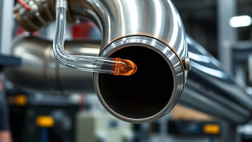
Back purging protects the inside of a stainless steel exhaust weld while the root is molten and cooling. The key is to create a small, controlled purge chamber around the joint, displace the air with argon, and maintain a gentle flow without pressurizing the tube. Correct gas units, clean metal, a controlled outlet, and careful root inspection all matter.
Quick Answer
To back purge stainless steel exhaust tubing, seal the purge area except for one argon inlet and one open vent. Feed pure argon into the lower side, start near 15–20 CFH, and verify that air has been displaced. Then weld using the lowest stable flow that keeps the root protected without building pressure.
Key Takeaways
- Use CFH, not CFM, when setting a typical welding flowmeter for a small exhaust purge.
- Seal uncontrolled openings, but always leave a vent so the tube cannot build pressure.
- Feed argon into the lower side of the purge chamber and let displaced air leave from the higher side when the joint position allows it.
- Keep the purge chamber as small as practical and verify the atmosphere with a weld-purge oxygen monitor when repeatability matters.
- A gray, black, crusty, or sugary root signals inadequate shielding and may require the joint to be removed and rewelded.
- Use local exhaust or adequate ventilation because argon can displace breathable air and stainless welding can create hazardous fumes.
At a Glance
| Time Required | About 10–20 minutes for cleaning, sealing, and purging a simple exhaust joint; complex assemblies can take longer. |
| Difficulty | Intermediate; consistent TIG control, clean fit-up, and safe compressed-gas handling are required. |
| Tools Needed | Argon cylinder, suitable regulator or dual flowmeter, purge hose, purge plugs or dams, heat-rated tape, vent, TIG equipment, PPE, and preferably a weld-purge oxygen monitor. |
| Cost | Low when the welding setup and argon supply are already available; dedicated purge plugs and low-ppm monitors add equipment cost. |
What’s in This Article
- Why Back Purging Is Essential for Exhaust Welds
- Preparing Your Equipment and Materials for Back Purging
- Designing the Purge Chamber
- Setting the Right Gas Flow Rate for Effective Purging
- Calculating Purge Volume and Time
- Step-by-Step Guide to Back Purging Your Exhaust System
- What to Watch Out For When Back Purging
- Inspecting the Weld Root
- Troubleshooting Common Back Purging Issues
- Benefits of Back Purging for Clean Welds
- Maintaining Your Welding Equipment
- Frequently Asked Questions
- Conclusion
- Sources
Warning: Never weld or heat a completely sealed exhaust tube. Keep a controlled purge outlet open so pressure cannot build. Argon is colorless and odorless and can displace breathable oxygen, especially in a vehicle, pit, tank, small room, or other enclosed area. Use adequate ventilation or local exhaust and follow all hot-work, PPE, cylinder, regulator, and welding-equipment instructions.
Why Back Purging Is Essential for Exhaust Welds
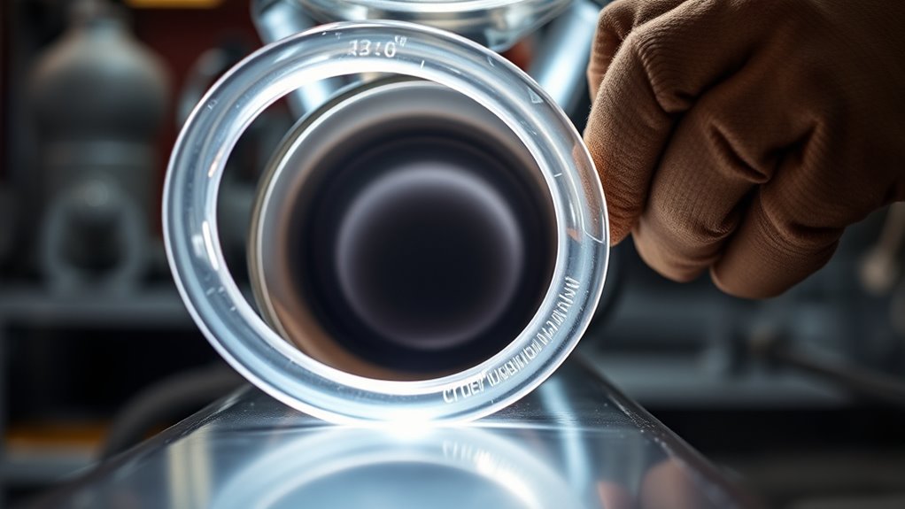
During TIG welding, torch gas protects the outside of the joint. It does not automatically protect the weld root inside the exhaust tube. Back purging fills the inside of the joint with an inert gas so the hot root is not exposed to normal air.
Without enough root shielding, oxygen can produce heavy discoloration, scale, and a rough crystalline surface commonly called sugaring. The result may trap contamination, reduce corrosion resistance, complicate inspection, and create more finishing or rework.
Stainless steel relies on chromium to form a thin passive oxide film that supports corrosion resistance. Nickel, molybdenum, titanium, niobium, and other alloying elements vary by grade. Heavy heat tint or root oxidation can leave the affected surface less resistant to corrosion. The Nickel Institute explains why stainless weld heat tint can cause corrosion problems.
Back purging is especially useful for thin-wall exhaust tubing, headers, downpipes, merge collectors, and joints that cannot be cleaned easily from the inside. It is also used when welding nickel alloys such as Inconel, although the exact gas, oxygen limit, and welding procedure may differ by alloy.
Note: Back purging improves the condition of the weld root, but it does not correct poor penetration, lack of fusion, excessive heat input, incorrect filler metal, or weak joint fit-up.
Preparing Your Equipment and Materials for Back Purging
Gather and inspect the complete purge setup before cleaning the joint. Interrupting the process after the tube has been cleaned or purged gives moisture, dust, and air more time to enter.
Products Worth Considering

Purging Kit: Includes 7 pairs of purging plugs covering sizes from 0.9" to 4.0" (3.5"-4.0", 3.0"-3.5", 2.5"-3.0", 2.0"-2.5", 1.5"-2.0", 1.2"-1.5", 0.9"-1.2"). Yellow and purple pieces form standard pairs. Comes with a 5-meter heavy-duty welding hose and a durable storage case for easy carry.
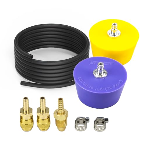
3.0 Inch Silicone Purge Plugs for thin-walled pipe welding, the silicone purge plug fits tightly against the pipe welding to prevent gas leakage, and the back of the weld is smooth and free of oxidation, saving the cost of secondary polishing.
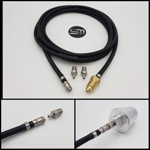
Quick On/Off Connection Of Back Purging Line Or Other Uses. Hooks Up Directly To Your Flowmeter/Regulator
Essential Tools Checklist
- Pure argon supply: Use the shielding or backing gas approved by the welding procedure and material manufacturer.
- Regulator and flowmeter: Use a regulator designed for argon and a flowmeter marked in CFH or liters per minute.
- Separate purge control: A dual flowmeter or second regulator lets you adjust torch flow and purge flow independently.
- Purge hose: Use clean hose that is suitable for shielding gas and free from oil, moisture, and cracks.
- Purge caps, plugs, or dams: Use heat-resistant parts that fit the tube without shedding fibers or melting near the heat-affected zone.
- Controlled outlet: Provide a vent on the opposite side of the purge chamber.
- Cleaning supplies: Use lint-free cloths, a suitable residue-free cleaner, and a stainless-only brush or abrasive.
- Inspection tools: A flashlight, inspection mirror, or borescope helps check the internal root.
- Optional weld-purge monitor: Use a low-ppm instrument designed for welding when the job requires repeatable oxygen control.
- Welding PPE and ventilation: Use the helmet shade, gloves, clothing, eye protection, ventilation, and respiratory controls required for the job.
Material Selection Tips
Match the purge plugs or dams to the exhaust diameter and temperature. Silicone plugs, expandable purge plugs, purpose-made inflatable dams, and heat-rated aluminum tape are common choices. Keep tape and temporary dams far enough from the arc that they cannot char, melt, or release fumes into the purge chamber.
Do not use oily foam, dirty rags, ordinary adhesive materials, or loose paper near the hot joint. Heated material can outgas and raise the oxygen or moisture level after the initial purge appears complete.
Confirm the exhaust alloy before selecting filler metal. For example, manufacturers commonly specify ER308L-type filler for many 304-series applications and ER316L-type filler for matching 316-series material. Stabilized or dissimilar joints may need another filler. Follow the filler-metal manufacturer, drawing, welding procedure specification, or exhaust-component manufacturer rather than choosing solely by appearance.
Use tools reserved for stainless steel. A carbon-steel wire brush, contaminated grinding disc, or dirty workbench can transfer free iron to the stainless surface and create later rust staining.
Cleaning the Joint Safely
- Deburr the cut ends and remove oxide, marking ink, oil, adhesive, and grinding residue.
- Clean both the outside and inside surfaces near the joint.
- Wipe the area with a clean, lint-free cloth and a suitable residue-free cleaner.
- Allow any flammable solvent, including isopropyl alcohol, to evaporate completely.
- Remove the solvent container, used cloths, and other combustibles from the hot-work area before striking an arc.
OSHA recommends removing coatings and solvent residue that could create hazardous exposure during welding. It also notes that stainless welding can produce hexavalent chromium fumes, so adequate ventilation or local exhaust is important. See OSHA’s guidance on controlling hazardous welding fumes and gases.
Designing the Purge Chamber
A good purge setup does not need to fill the entire exhaust system. In most cases, it is faster and more economical to isolate a short section around the joint with purge plugs or dams.
Products Worth Considering
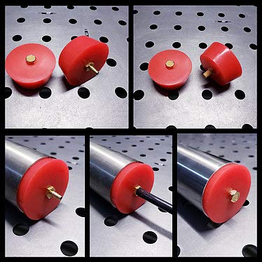
Easy Installation and Removal. Fitting sleeves can simply be pushed out and transferred to another plug. Since the sleeves are 1/8" NPT, you have the ability to use different fittings, and increase or decrease the feed/vent sizes. The internal diffuser fitting allows for a smooth, even, non turbulent argon flow into the tube/pipe. This allows for argon to fill the tube/pipe quicker, saving you on gas and time. Internal diffusers are a must when back purging, especially on larger diameter tube/pipe.
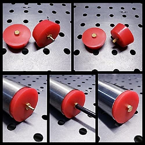
Easy Installation and Removal. Fitting sleeves can simply be pushed out and transferred to another plug. Since the sleeves are 1/8" NPT, you have the ability to use different fittings, and increase or decrease the feed/vent sizes.
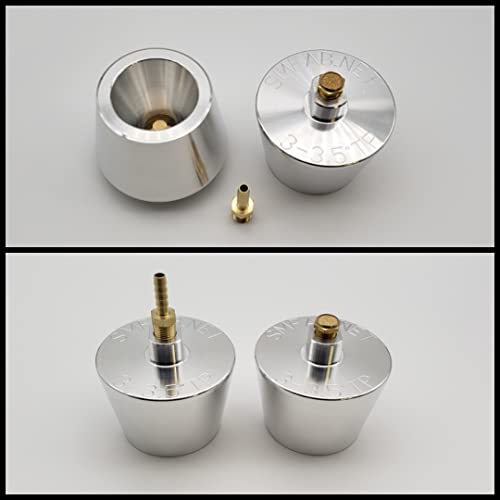
Easy Installation and Removal. Simply tap them into the pipe/tube, since they are tapered, they lock in place and you are ready to start back purging. For removal you can either tap the side of the raised wrench flats at the top of the plug, or you can put a wrench on the flats and twist them out.
Argon Inlet and Outlet Placement
Argon is heavier than air. When the joint position allows it, feed argon into the lower side of the purge chamber and place the outlet on the higher side. This arrangement helps the incoming argon displace air instead of mixing with it.
The outlet must remain open throughout the purge and root pass. It should be large enough to prevent pressure but small enough to limit uncontrolled air movement. Do not rely on a loose tape edge as the only vent because it can close as the assembly heats or moves.
Keep the Purge Volume Small
Place the dams close enough to the joint to reduce gas use, but far enough away that welding heat cannot damage them. Follow the purge-system manufacturer’s minimum distance and temperature limits.
Mufflers, catalytic converters, resonators, flex sections, valves, merge collectors, and long branches can trap air or create dead spaces. Isolate these components when practical. If they must remain connected, allow extra purge time and confirm the oxygen level at the outlet rather than assuming the complete assembly has purged evenly.
Pro Tip: Place the oxygen-monitor sampling tube near the outlet, not beside the argon inlet. The outlet is more likely to reveal trapped air, leaks, and contamination from the far side of the purge chamber.
Setting the Right Gas Flow Rate for Effective Purging
Gas-flow units are critical. Welding flowmeters in the United States commonly display cubic feet per hour (CFH), not cubic feet per minute. A setting of 20 CFM would equal 1,200 CFH and is not an appropriate purge setting for ordinary exhaust tubing.
Lincoln Electric’s stainless back-purging guidance recommends starting at approximately 15–20 CFH, which is about 7–9.5 liters per minute. Treat this as a practical starting point for a small tube setup, not a universal specification.
| Stage | Practical Setting | What to Check |
|---|---|---|
| Initial displacement | Begin near 15–20 CFH for a small exhaust purge chamber, then adjust for volume and outlet size. | Steady outlet flow, no damaged plugs, no closed vent, and no turbulent blast. |
| Before welding | Continue until the required oxygen level is reached or the approved purge procedure is complete. | Stable low-oxygen reading at the outlet when a purge monitor is used. |
| During the root pass | Reduce to the lowest stable flow that maintains the purge and slight outlet movement. | No pressure at the joint, no root disturbance, and no rising oxygen reading. |
| Cooling | Maintain purge gas until the hot root is no longer likely to oxidize, as required by the procedure. | Root color remains acceptable and plugs are not overheating. |
Do not confuse purge flow with torch shielding-gas flow. Each circuit serves a different area and should be controlled separately. Miller advises that excessive TIG shielding flow can create turbulence and draw surrounding air into the gas stream. The same principle is useful when adjusting a back purge: more flow is not automatically better. See Miller’s TIG gas-coverage troubleshooting guidance.
Oxygen-Level Targets
The acceptable oxygen level depends on the alloy, welding procedure, customer requirement, and desired root appearance. A dedicated weld-purge monitor is the most reliable way to confirm the purge before and during welding.
Huntingdon Fusion Techniques describes 100 ppm oxygen as a benchmark used for oxide-free, low-color stainless work and offers monitors designed for that range. A general workplace oxygen-deficiency alarm is not a substitute for a low-ppm weld-purge monitor. Learn more from HFT’s stainless weld-purge monitoring guidance.
For non-code automotive exhaust fabrication, the welder may also assess the completed root visually. However, appearance alone does not measure penetration, fusion, internal defects, or compliance with a qualified procedure.
Calculating Purge Volume and Time
Estimating the purge volume helps you avoid guessing. For a straight cylindrical section, use the tube’s internal diameter and the distance between the purge dams.
Internal volume in cubic inches:
3.1416 × internal radius² × purge length
Convert cubic inches to cubic feet:
Cubic inches ÷ 1,728
Estimated purge time in minutes:
Purge volume in cubic feet × planned volume changes ÷ flow in CFH × 60
For example, a 24-inch-long purge chamber with a 2.5-inch internal diameter contains about 0.068 cubic feet. At 15 CFH, eight theoretical volume changes take about 2.2 minutes.
That result is only an estimate. Real systems may need more time because of air mixing, leaks, branches, mufflers, moisture, damaged seals, or materials that release vapor as they warm. Five or six volume changes may provide an initial estimate for a simple chamber, but they do not prove that the oxygen level is acceptable.
Note: Use the volume calculation to estimate when to begin checking the outlet. Use a weld-purge monitor, qualified procedure, or verified shop method to decide when the atmosphere is actually ready for welding.
Step-by-Step Guide to Back Purging Your Exhaust System
- Confirm the material and procedure: Identify the stainless grade, wall thickness, filler metal, required joint gap, welding settings, and any customer or code requirements.
- Dry-fit the parts: Align the exhaust pieces and create a consistent joint. Poor fit-up can cause uneven penetration and make the purge harder to contain.
- Clean the joint: Remove burrs, oxide, oil, adhesive, moisture, and contamination from both sides of the joint. Allow cleaning solvent to evaporate completely.
- Install the purge dams: Place clean, heat-resistant plugs or dams on both sides of the joint to isolate the smallest practical volume.
- Connect the argon inlet: Feed argon into the lower side of the chamber when possible. Keep the hose end from pointing directly at the root, where a concentrated jet may create turbulence.
- Create the outlet: Leave a controlled vent at the higher or opposite side. Confirm that the outlet cannot be blocked by tape, a hot plug, molten metal, or a changing joint gap.
- Check the setup for leaks: Inspect fittings, hose connections, plugs, tape, and the joint. Leak-test gas fittings before hot work, then remove and dry any leak-detection liquid.
- Start the purge: Begin near 15–20 CFH for a small exhaust chamber and allow enough time to displace the air.
- Verify the atmosphere: Measure oxygen near the outlet when a purge monitor is available. Wait for a stable reading that meets the job’s procedure or acceptance target.
- Tack under purge: Keep the purge active while placing tacks so their roots do not oxidize. Use small, evenly spaced tacks that can be incorporated into the final weld.
- Reduce to maintenance flow: Lower the purge to the minimum flow that maintains the required atmosphere and slight outlet movement. Never close the vent to conserve argon.
- Weld the joint: Keep a short, controlled arc and use the heat input, filler size, travel speed, and torch-gas setting required for the material.
- Manage the closing section: As the weld closes, confirm that the separate outlet remains open. Do not use the shrinking unwelded gap as the only vent.
- Continue the purge during cooling: Maintain shielding long enough to protect the hot root, according to the material and welding procedure.
- Inspect the result: Use a light, mirror, or borescope to check the entire root for discoloration, sugaring, incomplete penetration, excessive penetration, undercut, or missed areas.
What to Watch Out For When Back Purging
| Issue | Recommendation | Possible Result if Ignored |
|---|---|---|
| Wrong flow unit | Read the flowmeter in CFH or liters per minute, not CFM. | Extreme gas waste, turbulence, damaged seals, or root disturbance. |
| Closed outlet | Keep a separate, controlled vent open throughout purging and welding. | Pressure buildup, a disturbed weld pool, expelled plugs, or molten-metal blowout. |
| Loose seals | Reseal uncontrolled gaps and inspect the hose and fittings. | Air enters the chamber and oxidizes the root. |
| Excessive flow | Reduce flow after the initial purge and avoid directing a high-speed jet at the joint. | Turbulence, unnecessary mixing, pressure, and wasted argon. |
| Dam too close to the joint | Follow the plug or dam manufacturer’s heat-distance limit. | Melting, outgassing, smoke, contamination, or loss of the seal. |
| Dirty or wet chamber | Remove oil, moisture, paper, loose fibers, adhesive residue, and dirty tools. | Porosity, rising oxygen readings, discoloration, or an unstable arc. |
| Complex exhaust components | Isolate dead spaces or confirm the atmosphere at the farthest outlet. | Trapped air remains even though gas is flowing at the inlet. |
| Poor ventilation | Use local exhaust or adequate general ventilation and keep your head out of the fume plume. | Exposure to welding fumes or an oxygen-deficient atmosphere. |
Inspecting the Weld Root
Inspect the full circumference after the joint has cooled enough to handle safely. Root color is a useful warning sign, but the permitted condition depends on the welding procedure and service requirements.
| Root Appearance | Likely Meaning | Action |
|---|---|---|
| Bright silver or very light tint | Generally indicates effective root shielding. | Still check penetration, fusion, profile, and the applicable acceptance criteria. |
| Straw, gold, blue, or purple tint | Increasing oxygen exposure or heat tint. | Compare with the WPS or customer standard; improve the purge before the next weld. |
| Gray or black scale | Substantial oxidation, leakage, poor purge timing, or excessive heat. | Evaluate for removal and rework; do not hide the condition with external polishing. |
| Rough, crusty, or crystalline “sugar” | Severe root oxidation. | The safest correction is usually to remove the affected joint, restore clean metal, and reweld with an effective purge. |
| Large droop or excessive penetration | Too much heat, a large gap, slow travel, poor fit-up, or purge pressure affecting the pool. | Correct fit-up and welding variables; check that the vent is open and purge pressure is low. |
If heat tint must be removed, use a process suitable for the alloy and component. Mechanical cleaning must use stainless-only tools. Chemical pickling and passivation involve hazardous acids and should be performed only with the correct products, PPE, training, ventilation, disposal controls, and manufacturer instructions. See the worldstainless overview of stainless surface treatment.
Troubleshooting Common Back Purging Issues
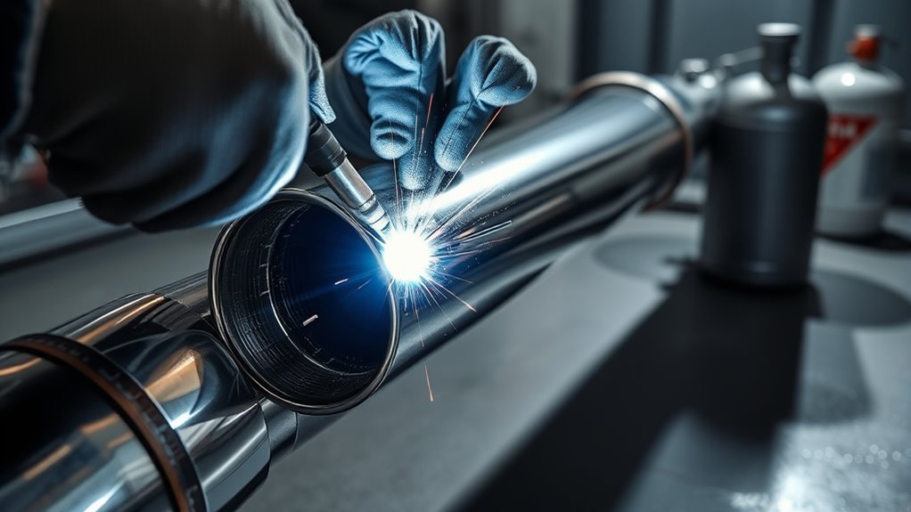
When a root oxidizes, begin with the purge system before changing amperage or filler technique. Several problems can occur at the same time.
- Confirm the unit: Make sure the flowmeter is being read in CFH or liters per minute, not CFM.
- Check the outlet: Verify that it is open, separate from the closing weld gap, and not blocked by tape or a plug.
- Inspect every seal: Look for loose purge caps, split hose, lifting tape, open branches, slip joints, and disconnected sensors or bungs.
- Check gas delivery: Confirm that the argon cylinder is open, the correct regulator is installed, the hose is not kinked, and the flowmeter ball moves freely.
- Reduce turbulence: Keep the inlet from blasting directly at the weld root and lower the flow after the initial displacement stage.
- Allow more purge time: Long assemblies and components with internal chambers need more time than a short straight tube.
- Move the sampling point: Measure oxygen at the far outlet rather than near the argon inlet.
- Remove contamination: Replace dirty plugs, damp materials, oily hose, charred tape, and shedding foam.
- Check the torch shield separately: A clean purge cannot correct poor gas coverage on the outside of the weld.
- Review heat input and fit-up: Excessive amperage, slow travel, a wide gap, or repeated reheating can darken the root even when the purge has improved.
Pro Tip: If the first tack is already gray or sugary, stop and correct the purge. Adding more tacks or completing the weld will not restore the oxidized root.
Benefits of Back Purging for Clean Welds: Quality and Performance
Effective back purging reduces oxidation on the back side of stainless steel and nickel-alloy welds. It helps produce a smoother root, preserves a cleaner surface, and reduces the chance that the joint must be cut apart and rewelded.
A clean root also avoids the rough internal buildup associated with sugaring. This prevents an unnecessary obstruction inside headers, downpipes, and custom exhaust tubing, although back purging alone should not be presented as a guaranteed horsepower or exhaust-flow upgrade.
The greatest benefits are consistency, lower rework risk, easier visual inspection, and better preservation of the stainless surface. These benefits matter most on thin tubing and joints that cannot be cleaned from the inside after assembly.
Back purging requires extra setup time and argon. Keeping the purge chamber small, sealing leaks, calculating the volume, and reducing to maintenance flow after the initial purge help control gas use.
Best Practices for Maintaining Your Welding Equipment
- Secure the cylinder: Keep compressed-gas cylinders upright and protected from impact, heat, sparks, and electrical contact.
- Use the correct regulator: Confirm that the regulator, flowmeter, hose, and fittings are rated for argon and the cylinder pressure.
- Inspect for leaks: Check the regulator connection, flowmeter, hose, tees, valves, plugs, and couplings before use.
- Protect hose cleanliness: Cap purge hoses during storage and replace hose contaminated with oil, water, or debris.
- Clean the torch: Inspect the cup, gas lens, collet body, O-rings, and torch fittings so external shielding remains stable.
- Keep stainless tools separate: Store stainless brushes and abrasives away from carbon-steel fabrication tools.
- Replace heat-damaged purge parts: Do not reuse plugs, tape, or dams that have melted, hardened, cracked, or absorbed contamination.
- Calibrate the monitor: Maintain and calibrate the weld-purge monitor according to its manufacturer’s instructions.
- Maintain ventilation: Position local exhaust close enough to remove fume without pulling away the torch shielding gas.
- Remove fire risks: Keep flammable materials, solvent containers, fuel residue, wiring, upholstery, and underbody coatings away from the hot-work area.
Frequently Asked Questions
Should you back purge stainless exhaust?
Back purging is recommended when you want a clean, low-oxidation root inside stainless exhaust tubing. It is especially valuable on headers, downpipes, collectors, and other joints that cannot be cleaned internally after welding.
How do you get clean stainless steel welds?
Use clean stainless material, dedicated tools, close and consistent fit-up, suitable filler metal, correct TIG polarity and heat input, stable torch shielding, and an effective root purge. Keep oil, moisture, carbon-steel contamination, drafts, and damaged gas fittings away from the joint.
Can you weld stainless steel exhaust without purging?
It is physically possible, but the unshielded root may oxidize heavily or develop sugaring. Whether that result is acceptable depends on the joint design and service requirement. For a clean internal root, back purging is the more reliable method.
Is back purging always necessary?
No single rule covers every stainless joint or welding process. Back purging is normally used when the exposed root must remain clean and corrosion resistant. A qualified welding procedure may allow another root-protection method, so follow the applicable specification.
How long should you purge before welding?
The time depends on the internal volume, flow in CFH, outlet size, seal quality, and number of branches or chambers. Calculate an estimated purge time, then verify the atmosphere at the outlet. Do not rely on one fixed number of minutes for every exhaust assembly.
What argon flow should you use for back purging?
For a small stainless exhaust purge chamber, approximately 15–20 CFH is a practical initial setting. After the air has been displaced, reduce the flow to the lowest level that maintains the required oxygen reading and slight outlet movement. Never use CFM values from ordinary welding flowmeters.
Can too much purge gas damage the weld?
Yes. Excessive flow can create turbulence, waste argon, damage temporary seals, and build pressure if the outlet is restricted. Pressure at the joint can push against the molten root and change its profile.
Do you need an oxygen monitor?
A monitor is not used on every hobby exhaust weld, but it provides much better repeatability than judging purge time alone. Use a low-ppm instrument designed for weld purging when the procedure specifies an oxygen limit or when failed welds would be expensive to replace.
Can nitrogen replace argon for the purge?
Nitrogen is used as a backing gas in some approved procedures and with some stainless grades, but it is not a universal substitute. Gas choice can affect weld chemistry and properties. Use pure argon unless the material manufacturer or qualified welding procedure specifically approves another gas.
Conclusion
Back purging a stainless steel exhaust weld is a controlled gas-displacement process, not simply a matter of taping the pipe and turning the argon up. Build a small purge chamber, provide a lower inlet and open outlet, use CFH rather than CFM, and wait until the internal atmosphere is ready before welding.
Keep the purge active through the tacks, root pass, and required cooling period. Then inspect the entire internal root. A bright, smooth root confirms that the setup is moving in the right direction, while gray scale or sugaring means the purge system, cleanliness, fit-up, or heat input must be corrected before the next joint.
Sources
- Lincoln Electric — Back Purging Stainless Steel — supports the 15–20 CFH initial purge guidance.
- Miller Electric — Common TIG Welding Problems — explains gas-coverage problems, leaks, and turbulence from excessive flow.
- Huntingdon Fusion Techniques — Stainless Weld-Purge Monitoring — supports low-ppm oxygen measurement and the distinction between purge monitors and ambient oxygen monitors.
- Occupational Safety and Health Administration — Controlling Hazardous Fume and Gases During Welding — supports ventilation, argon-asphyxiation, solvent-residue, and stainless-fume warnings.
- Nickel Institute — Heat Tints on Stainless Steels Can Cause Corrosion Problems — supports the discussion of oxidation and reduced corrosion resistance.
- worldstainless — Stainless Steel Surface Treatment — supports post-weld heat-tint removal, pickling, passivation, and contamination-control guidance.




