To read auto body weld diagrams, start with the reference line, follow the arrow to the joint, then check the weld symbol, size, length, spacing, tail notes, and supplementary symbols. The diagram tells you what weld to make, where to place it, and which repair notes apply. Use the current AWS A2.4:2020 welding-symbol standard as your symbol reference, but always confirm the final repair method in the vehicle maker’s OEM procedure before welding.
Quick Answer
Read an auto body weld diagram in this order: reference line, arrow, weld symbol, side of joint, size, length, pitch, tail notes, and supplementary symbols. Then compare the diagram with the OEM repair procedure so the weld type, location, material, and inspection method match the vehicle’s repair requirements.
Key Takeaways
- The reference line anchors the weld symbol, while the arrow points to the joint being repaired.
- A symbol below the reference line usually means the arrow side; a symbol above the line usually means the other side.
- Size is commonly shown to the left of the weld symbol, while length and pitch are commonly shown to the right.
- The tail can list the welding process, filler, inspection method, or other repair notes.
- A circle at the arrow/reference-line junction means weld all around, not a separate “complete joint” instruction.
- In collision repair, the OEM procedure controls the final weld method, even when the diagram looks simple.
At a Glance
| Time Required | 5–10 minutes for a simple diagram; longer when checking OEM repair procedures, materials, corrosion protection, and inspection notes. |
| Difficulty | Beginner to intermediate, depending on the symbol detail and repair location. |
| Tools Needed | OEM repair manual, weld-symbol chart, tape measure or scale, PPE, welding setup notes, and inspection checklist. |
| Cost | Usually no added cost if you already have access to the repair manual; OEM subscriptions, training, or certification may cost extra. |
What Are Auto Body Weld Diagrams?

Auto body weld diagrams are technical illustrations that show you where and how welds should be made during a vehicle structure or body-panel repair. They turn repair instructions into a visual map, so you can identify the joint, weld type, weld size, spacing, process notes, and inspection requirements before you strike an arc.
You use auto body weld diagrams to read the weld symbols, weld type, weld size, and process notes that guide the welding process. These diagrams often follow AWS-style symbol conventions, while the vehicle maker’s repair manual tells you the exact repair method for that year, make, model, material, and panel location.
Each diagram acts as a communication tool between engineers, repair planners, and technicians. It reduces guesswork, helps you match the original load path, and keeps the repair tied to the intended structure instead of to habit or memory.
When you follow these diagrams correctly, you protect structural integrity and help keep the vehicle aligned with its intended crash performance. If you misread them, you risk weak joints, poor fit, hidden corrosion paths, and rework. Understanding the right welding processes also helps you choose the correct method for the repair task.
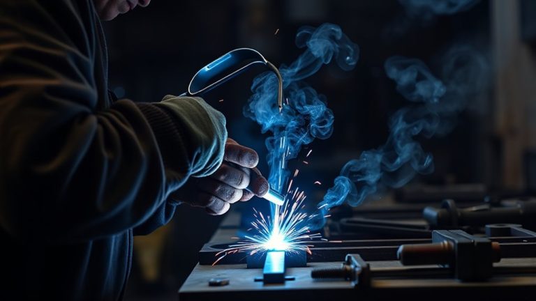
Warning: Welding on a vehicle can create fire, fume, electrical, airbag, battery, and high-voltage hazards. Wear proper PPE, protect nearby trim and glass, remove coatings only as the OEM procedure allows, keep fire protection nearby, and use adequate ventilation. Do not weld in confined spaces or on energized systems unless the repair procedure and safety controls allow it.
How to Read Auto Body Weld Symbols
You read an auto body weld symbol as a code. The reference line, arrow, and symbol type tell you what weld to make and where to place it. Then the size, length, pitch, tail notes, and supplementary symbols tell you how the weld should be completed. Understanding flux core welding techniques can also help when the approved repair method calls for that process.
Step-by-Step Reading Order
Use the same reading order every time so you do not skip a small note that changes the repair:
- Find the reference line, because it anchors the full welding symbol.
- Trace the arrow to the exact joint or edge being repaired.
- Check whether the symbol is on the arrow side, other side, or both sides.
- Identify the weld type, such as spot, plug, seam, fillet, groove, MIG, TIG, or brazed joint.
- Read the size, length, pitch, or number of welds.
- Check the tail for process, filler, inspection, or repair notes.
- Look for supplementary symbols, including field weld, weld-all-around, contour, or finish marks.
- Compare the diagram with the OEM repair procedure before cutting, drilling, clamping, or welding.
Weld Symbol Basics
Weld symbols translate repair requirements into a standardized visual code. They tell you what joint to make, how to make it, and where to place it.
You start at the reference line, which organizes the technical information for the joint. The arrow links that line to the joint, and the symbol identifies whether you need fillet welds, groove welds, plug welds, spot welds, seam welds, or another weld form.
Supplementary symbols add critical detail, such as field work, all-around welds, contour, or finish. The tail can specify welding processes, filler metal, adhesive use, inspection needs, or other repair specifications.
In auto body repair, this system gives you repeatable instructions. Instead of guessing from the old welds you removed, you can match the repair plan to the diagram and the OEM procedure.
Symbol Placement Rules
Every weld symbol follows a fixed layout on the reference line. You read the basic structure by tracing the arrow to the joint, then checking where the symbol sits in relation to the line.
In common AWS-style notation, a symbol below the reference line usually means the arrow side of the joint. A symbol above the line usually means the other side. Symbols on both sides of the line usually mean both sides require welding.
Tail information can name the process or inspection needs, while supplementary symbols refine the job status. In technical drawings, this layout helps you work in order:
- Identify the type of weld.
- Verify the side of the joint.
- Confirm size, length, spacing, or number of welds.
- Check for field-work, all-around, finish, or inspection notes.
When you decode each element in order, you reduce errors and avoid welding the wrong side of the joint.
Repair Spec Details
Repair spec details on auto body weld diagrams tell you exactly what kind of weld to make, where to place it, and how large or frequent it needs to be.
You read the welding symbols from the reference line, then follow the arrow to the joint. If the symbol sits on the arrow side, weld that side unless the diagram or OEM procedure says otherwise.
Use fillet welds for many corner and tee-style joints, groove welds for many butt joints, and plug welds for many lap repairs where a removed resistance spot weld is being replaced. In collision repair, do not assume a plug weld can replace a spot weld unless the OEM procedure allows it.
Check the tail of the weld symbol for process notes, material specs, filler requirements, adhesive instructions, corrosion protection, and inspection requirements.
Pro Tip: Mark the diagram with a pencil or digital note before welding. Circle the weld type, underline the size and pitch, and check off the tail notes after you confirm the OEM procedure.
Reference Line, Arrow, and Tail Explained
You use the reference line as the base of the welding symbol. It anchors the weld type, location, size, and notes. The arrow points to the joint and helps show which side gets the weld. The tail can add method, filler, inspection, material, or repair-process notes. Read the symbol in order so you do not miss any required instruction. Understanding metal selection importance also helps you match the diagram to the correct material and welding process.
Reference Line Basics
A weld symbol starts with the reference line, which anchors the entire notation. You read every weld symbol from that line first because it organizes the symbols and controls how the rest of the information is interpreted.
The arrow identifies the joint, including edge-to-edge, lap, flange, corner, and butt-style joints. The tail can add process or inspection notes, tightening the meaning without crowding the drawing.
To avoid mistakes, follow this sequence:
- Identify the reference line.
- Trace the arrow to the joint.
- Check symbol placement above or below the line.
- Read the dimensions and spacing.
- Check the tail for extra requirements.
This method keeps your reading precise and helps you decode diagrams with confidence.
Arrow And Tail Roles
Once you identify the reference line, the arrow and tail tell you where and how to weld. The arrow extends from the welding symbol to the joint, showing the exact location and whether the weld belongs on the arrow side, the other side, or both sides. The tail carries supplementary information, such as process notes, filler details, inspection rules, or OEM repair conditions.
| Element | Function | What You Check |
|---|---|---|
| Reference line | Anchors the symbol | Symbol position, size, length, and pitch |
| Arrow | Points to the joint | Exact panel edge, flange, lap, or seam |
| Tail | Lists supplementary information | Process, filler, inspection, and repair notes |
Read each mark in sequence: reference line, arrow, symbol placement, dimensions, tail. That order helps you complete the weld as specified instead of relying on memory.
Common Weld Types in Repair Specs
Repair specs commonly call out several weld types, and each one serves a distinct structural purpose. You read them to match the repair to the joint, not to guess.
Spot welds join overlapping materials at points, giving localized strength while preserving the behavior of many factory seams. Seam welds run continuously along panel edges, sealing and stabilizing the joint. Plug welds fill holes in overlapping materials and are often used where a spot weld has been removed, but only when the repair procedure allows that substitution.
Spot welds localize strength, seam welds seal edges, and plug welds can restore hidden strength when the OEM procedure calls for them.
MIG welds give you fast, versatile welding for many steel or aluminum repairs, while TIG welds give you precise control on thin sections and specialty work. These weld types are not interchangeable. Each one answers a specific load path, panel design, material, and heat-control requirement.
- Spot welds help preserve original panel behavior.
- Seam welds lock edges into one continuous joint.
- Plug welds rebuild lap-joint strength when approved.
- Fillet welds build triangular welds on corner, tee, or lap-style joints.
- Groove welds join prepared edges where deeper penetration is required.
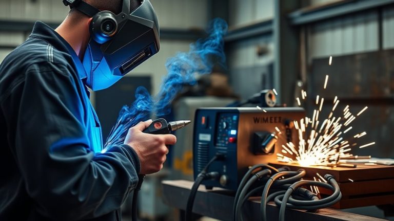
When you follow repair specs, you protect the vehicle and your work. The diagram tells you which welding method belongs where, while the OEM procedure tells you whether special equipment, adhesive, corrosion protection, or inspection is required. Understanding MIG welding settings can also improve repair quality when MIG welding is approved for the job.
How to Follow Weld Size and Spacing
Weld symbols tell you more than the weld type. They can also specify size, length, number of welds, and spacing. Read each dimension exactly as shown.
As a practical AWS-style reading habit, weld size is commonly shown to the left of the weld symbol, while length and pitch are commonly shown to the right. For intermittent welds, the first value usually shows the length of each weld segment, while the pitch value shows the center-to-center spacing between segments. In fillet welds, check leg sizes carefully; unequal legs need two dimensions.
Using proper protective clothing is also part of executing these precise welds safely.
| Marking | Meaning | Action |
|---|---|---|
| Left-side size | Weld size | Match the specified dimension |
| Right-side number | Length of the weld | Control coverage |
| Length-pitch format | Intermittent weld spacing | Set each segment and center-to-center pitch |
| Two leg values | Unequal fillet legs | Measure both legs |
| Complete spec | Repair requirement | Verify against the OEM procedure |
You keep repair work consistent when you follow every dimension. That precision protects strength, keeps joints compliant, and helps you avoid under-welding or over-welding the panel.
What Notes, Flags, and Standards Mean
After you match weld size and spacing, read the extra symbols and notes that control how the weld gets done. You decode welding symbols by checking the reference line, flags, tail information, and supplementary marks.
A flag at the reference line means field weld, so the weld is made at the installation or repair location rather than in the shop or factory setting. A circle at the junction of the arrow and reference line means weld all around, so the weld continues around the joint where the geometry allows it. Contour and finish marks can tell you whether the weld should be flush, convex, concave, ground, machined, or finished another way.
Use symbol tables in the manual to confirm each mark before you cut, clamp, drill, or weld.
- Verify the flag so you know whether the weld is field work or shop work.
- Read the tail for process, filler, adhesive, corrosion protection, or inspection demands.
- Apply welding standards, especially AWS A2.4:2020 for symbol interpretation, so your repair procedures stay consistent and repeatable.
- Confirm the vehicle maker’s procedure before replacing spot welds, sectioning panels, or welding advanced high-strength steel or aluminum.
When you follow the notes exactly, you protect fit, strength, corrosion resistance, and the vehicle’s path back to service. Also ensure proper ventilation in confined spaces to reduce exposure to harmful fumes during welding and cutting.
Note: AWS welding-symbol rules help you decode the drawing, but the vehicle maker’s repair manual controls the actual collision repair. If the OEM procedure says to use resistance spot welding, MIG brazing, adhesive, squeeze-type resistance spot welding, or a specific plug-weld pattern, follow that procedure.
OEM Repair Procedure Checks Before Welding
Before you weld, compare the diagram with the OEM repair procedure. Auto body diagrams often show the weld layout, but the repair manual may add details that are just as important as the symbol itself.
Check these items before you begin:
- Material type: mild steel, high-strength steel, ultra-high-strength steel, aluminum, galvanized steel, or mixed materials.
- Approved joining method: resistance spot weld, plug weld, MIG weld, MIG brazing, TIG weld, adhesive, rivet-bonding, or a combination.
- Panel preparation: coating removal, hole size, flange cleaning, adhesive application, and corrosion protection.
- Heat limits: some advanced steels and aluminum panels have strict heat-control requirements.
- Vehicle systems: battery disconnect, SRS precautions, EV high-voltage disable steps, sensor protection, and ADAS calibration requirements.
- Inspection: visual inspection, destructive test coupon, weld nugget check, plug-weld size check, or other verification method.
I-CAR’s collision repair resources emphasize that welding affects structural integrity and occupant safety after a collision, so safe repairs depend on training, correct procedures, and current OEM guidance.
Common Mistakes When Reading Weld Diagrams
Small symbol-reading mistakes can become large repair problems. Watch for these common errors:
- Ignoring arrow side versus other side: Welding the wrong side can weaken the joint or create poor panel fit.
- Skipping the tail: The tail may list the process, filler, inspection method, or special repair note.
- Misreading pitch: Pitch is spacing from center to center, not always the empty gap between welds.
- Confusing weld-all-around marks: A circle at the arrow/reference-line junction means weld all around.
- Copying old factory welds without checking the manual: The replacement procedure may use a different approved method.
- Forgetting corrosion protection: Bare metal, burned coatings, and unsealed seams can lead to rust after the repair.
- Using the wrong process for the material: Aluminum, galvanized steel, and advanced high-strength steel may require different heat control, filler, or joining methods.
Frequently Asked Questions
How do you interpret welding blueprints and specifications?
Start with the reference line, then follow the arrow to the joint. Identify the weld type, side of joint, size, length, pitch, tail notes, material requirements, inspection method, and safety notes. For auto body work, finish by checking the OEM repair procedure because the vehicle maker’s instructions control the final repair method.
What does 1G, 2G, 3G, and 4G mean in welding?
For common plate groove-weld position shorthand, 1G means flat, 2G means horizontal, 3G means vertical, and 4G means overhead. These positions affect puddle control, travel speed, heat input, penetration, and inspection expectations.
How do you read engineering drawings for welding?
Read the drawing notes first, then decode the welding symbol. Look for the reference line, arrow, symbol placement, weld size, weld length, pitch, contour, finish, process notes, material thickness, filler material, inspection requirements, and any welder qualification notes.
How do you calculate weld repair percentage?
Divide the repaired weld length by the total weld length, then multiply by 100. For example, if 8 inches of a 40-inch weld line was repaired, the weld repair percentage is 20%. Use the repair percentage with inspection notes, defect records, and post-repair testing requirements.
What does the circle on a welding symbol mean?
A circle at the junction of the arrow and reference line means weld all around. It tells you the weld continues around the joint where the joint shape allows it. Do not treat it as a separate open-circle versus closed-circle instruction.
Can you replace factory spot welds with plug welds?
Only if the OEM repair procedure allows it. Plug welds are common in collision repair, but some locations require squeeze-type resistance spot welding, MIG brazing, adhesive, rivets, or a specific weld pattern. Always check the vehicle maker’s procedure before substituting one weld type for another.
Conclusion
Now that you can read auto body weld diagrams and repair specs, you can turn complex lines and symbols into a clear repair plan. The reference line, arrow, symbol, size, pitch, tail, and supplementary marks are not decoration; they are the instructions that keep the weld in the right place and at the right strength.
Use AWS A2.4:2020 to understand the symbol language, then confirm the repair with the OEM procedure. When you follow weld type, size, spacing, notes, safety steps, and inspection requirements with care, you keep the repair aligned with OEM standards. In collision work, precision is the compass, and the diagram is the map that keeps the repair on course.
Sources
- American Welding Society — AWS A2.4:2020 Standard Symbols for Welding, Brazing, and Nondestructive Examination — backs welding-symbol standard and symbol interpretation.
- OSHA 1910.252 — General Requirements for Welding, Cutting, and Brazing — backs welding PPE, fire prevention, fumes, and ventilation safety.
- I-CAR Welding Training & Certification — backs collision welding, structural integrity, occupant safety, and OEM welding-resource context.
- I-CAR Repairability Technical Support Portal — backs using OEM information and repairability resources during collision repair planning.
- I-CAR Gold Class Standards for Collision Repair — backs collision-repair training, role-specific repair knowledge, and welding training expectations.