
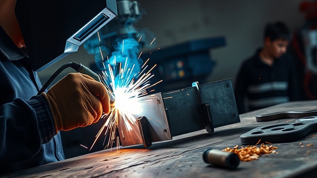
Welding auto body panels takes more than making a bead on thin steel. You must first confirm that the vehicle maker allows the panel to be sectioned and welded, identify the metal, remove fire and fume hazards, and test your settings on matching scrap. This guide explains the process for an OEM-approved, nonstructural mild-steel patch.
Quick Answer
To weld an approved mild-steel auto body patch, cut back to solid metal, trim the patch for a small and even joint, and secure it flush. Make widely separated locating tacks, recheck the shape, then close the seam with short, skipped tacks. Inspect the weld, grind carefully, and restore all corrosion protection.
Key Takeaways
- Check the vehicle-specific body repair manual before you cut, weld, braze, bond, or section any panel.
- Use this general process only for an OEM-approved, nonstructural mild-steel patch.
- Practice on metal that matches the panel before welding the vehicle.
- Control distortion by using isolated tacks and moving around the seam instead of running a continuous bead.
- Inspect the weld before grinding, then restore primer, seam sealer, underbody protection, and cavity wax where required.
At a Glance
| Time Required | Several hours for a small patch; more time for shaping, hidden corrosion, coating removal, and paint preparation |
| Difficulty | Intermediate to advanced; structural, restraint-related, aluminum, HSS, and UHSS repairs require trained collision-repair work |
| Tools Needed | OEM repair information, MIG or TIG equipment approved for the job, clamps, cutting and sanding tools, body hammer and dolly, PPE, ventilation, and fire protection |
| Cost | Relatively low for patch metal, wire, gas, abrasives, and coatings if you already own the equipment; substantially higher if you must buy welding and bodywork tools |
What’s in This Article
- Check the OEM Procedure and Panel Material
- Tools and Safety Gear
- Before You Begin
- Estimated Time
- Step 1: Cut Damaged Metal
- Step 2: Scribe and Trim the Patch
- Choose MIG or TIG
- Step 3: Clamp and Tack
- Step 4: Close the Seam
- Step 5: Grind the Weld
- Step 6: Inspect and Correct the Repair
- Step 7: Prepare and Protect the Surface
- Common Welding Problems
- When Not to DIY the Repair
- Frequently Asked Questions
- Conclusion
- Sources
Check the OEM Procedure and Panel Material First
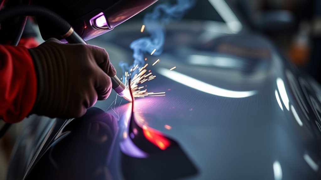
Before you remove damaged metal, find the vehicle-specific body repair procedure. The procedure should tell you whether the panel can be repaired or sectioned, where cuts may be made, what metal the panel contains, and which attachment method is required.
This check matters because modern bodies may contain mild steel, galvanized steel, high-strength steel, ultra-high-strength steel, aluminum, and several materials layered together. According to I-CAR’s collision-repair guidance, some heat-sensitive parts cannot be installed with conventional gas metal arc welding. The approved method may instead use resistance spot welding, MIG brazing, adhesive, rivets, or a combination of methods.
The vehicle maker’s current, part-specific repair procedure overrides any general welding technique.
Know Whether the Panel Is Cosmetic or Structural
A small patch in an approved outer skin is different from a repair to a pillar, rail, rocker reinforcement, roof rail, apron, floor reinforcement, suspension mounting area, seat-belt mounting area, or airbag-related structure.
Do not assume a panel is nonstructural because you can see it from outside. An outer panel may cover several structural layers. If you cannot confirm the construction and approved cut location, stop before cutting.
Warning: Do not use this general patch method on a structural or restraint-related panel, an unknown steel grade, an aluminum body structure, or a location that the OEM does not approve for sectioning. An incorrect repair can change crash performance.
Tools and Safety Gear You Need
Gather your repair information, welding equipment, cutting tools, clamps, shaping tools, safety gear, and corrosion-protection products before starting. Stopping midway can leave bare metal exposed or tempt you to continue with the wrong tool.
Products Worth Considering

Value Pack: The package includes 24 packs of butt welding clamps, enough quantity to meet your daily needs and replacements. Each butt welding clamps is individually wrapped in a small bag, convenient to carry and use.

Highly Durable Design: The shell of stud welder kit is made of high-quality ABS body, has good stability under high temperature conditions, withstand temperature of 93-118℃, and the movement is pure copper electrode. This welder stud kit is wear-resistant, strong and sturdy.

Adaptability: Our butt welding clamps are suitable for both straight panels or curved panels. Maintains 0.40" gap between panels for edge-to-edge welding.They will work well in these 2 kinds of p
Welding and Bodywork Tools
- Vehicle-specific body repair manual or approved repair procedure
- MIG, TIG, resistance spot, brazing, bonding, or riveting equipment specified by the procedure
- Replacement patch made from the correct material and similar thickness
- Sheet-metal clamps, butt-weld clamps, magnets, or temporary fasteners suitable for the repair
- Scriber, marker, ruler, flexible contour gauge, and measuring tape
- Angle grinder, air saw, nibbler, or other controlled cutting tool
- Grinding and sanding accessories rated for the tool’s maximum speed
- Body hammer, suitable dolly, pick tools, and straightedge
- Wire brush and dedicated stainless brush where the material requires one
- OEM-approved primer, seam sealer, underbody coating, and cavity protection
- Clean same-type and same-thickness scrap for setting up and testing the welder
When cutting or grinding, check the accessory’s type and maximum speed. The wheel must be rated at or above the grinder’s no-load speed. The guide to angle grinder wheel markings explains how to read those ratings.
Never install a toothed wood-cutting or circular-saw blade on an angle grinder unless the grinder and accessory manufacturer specifically approve the combination. Review the hazards before considering a saw blade on an angle grinder.
Common MIG Setup for an Approved Mild-Steel Patch
For ordinary light-gauge mild-steel bodywork that the OEM allows you to MIG weld, a common starting setup is .023 or .024-inch solid wire, electrode-positive polarity, and 75% argon with 25% carbon dioxide shielding gas. ER70S-6 is a common mild-steel wire.
These are starting points, not universal specifications. Follow the wire maker’s instructions, the welder chart, and the OEM procedure. Miller’s automotive MIG guidance explains that voltage and wire speed depend on the metal, thickness, joint, position, wire diameter, and shielding gas.
Make several welds on matching scrap before touching the vehicle. Adjust the machine until the arc is stable and the weld ties into both sides without blowing a hole. Cut, bend, or break a test coupon when practical so you can check fusion instead of judging only the bead’s appearance.
Personal Protective Equipment
- Welding helmet with the correct lens shade for the process
- Safety glasses with side protection under the helmet
- Flame-resistant jacket or sleeves
- Dry welding gloves
- Long pants without open cuffs and closed leather footwear
- Hearing protection for cutting and grinding
- Face shield over safety glasses when grinding
- Respiratory protection when required by the coating, fume assessment, and local rules
Use local fume extraction close to the arc when possible, without pulling shielding gas away from the weld. OSHA’s welding standard includes ventilation requirements for welding and cutting, including work involving zinc-bearing coatings. NIOSH also warns that fumes from zinc, chromium, nickel, lead, cadmium, and other metals can be more hazardous than fumes from ordinary mild steel.
If the panel is galvanized, identify the coating and follow the OEM procedure before removing material. The guide to removing zinc coating from galvanized steel covers preparation, but grinding away zinc does not eliminate the need for ventilation or later corrosion protection.
Warning: Do not weld over paint, filler, seam sealer, undercoating, sound-deadening material, fuel residue, or an unknown coating. Heating these materials can create toxic fumes, hidden fires, and weld contamination.
Before You Begin
Prepare the vehicle and work area before cutting. Sparks can travel through gaps, land behind trim, or ignite insulation on the opposite side of the panel.
- Read the complete procedure: Confirm the cut location, joint design, attachment method, weld type, and required corrosion protection.
- Inspect both sides: Find wiring, modules, fuel and brake lines, airbag components, glass, trim, carpet, foam, seam sealer, and sound insulation near the work.
- Follow the OEM power-down process: Use the exact battery, supplemental-restraint, hybrid, or EV shutdown procedure for the vehicle. Do not improvise around a high-voltage system.
- Remove combustibles: Remove nearby trim and insulation when possible. Use proper welding blankets to protect items that cannot be removed.
- Control fuel hazards: Do not weld on a fuel tank, fuel container, or area exposed to fuel vapors. Move the repair to a qualified facility if the work is near a tank or fuel line and the OEM procedure does not provide a safe method.
- Prepare fire protection: Keep a suitable extinguisher nearby, inspect the hidden side during the job, and continue checking for heat or smoke after welding stops.
- Prepare the work-clamp location: Use clean bare metal close to the weld so current has a short, direct path. Do not let welding current pass through bearings, hinges, electronic modules, or other sensitive parts.
- Clean the metal: Remove coatings far enough from the joint to prevent contamination, but do not strip a larger area than the repair and coating system require.
Note: Disconnecting a 12-volt battery alone does not make every vehicle safe to weld. Airbags, capacitors, multiple batteries, hybrid systems, and high-voltage components may require extra steps and waiting periods listed in the service information.
Estimated Time for Auto Body Panel Welding
A small cosmetic patch can take several hours once you include inspection, disassembly, cutting, shaping, test welding, fit-up, welding, grinding, corrosion protection, and surface preparation. The arc may run for only a few minutes, but most of the job is careful preparation and cooling time.
Hidden rust, curved body lines, double-wall construction, limited rear access, and previous filler can add substantial time. Do not rush the fit to save time. A poor gap usually creates more welding, more heat, and more grinding.
Step 1: Cut Away the Damaged Metal
Remove the damaged area only after you know the approved cut location and have inspected the hidden side. Cut back to sound metal. Rust that remains beside or behind the patch will continue to spread.
Choose a Controlled Cutting Tool
An angle grinder with a thin cutoff wheel can make straight cuts, but it also creates heat and a wide shower of sparks. An air saw, body saw, nibbler, or fine-tooth cutting tool may give you more control in tight areas.
Secure loose material and maintain a stable cutting position. The guide to cutting sheet metal with an angle grinder explains wheel positioning and workpiece control.
Measure and Mark the Opening
Mark the smallest approved repair area that reaches solid metal and gives you room to shape and weld the patch. Use reference points, body lines, contours, and nearby edges to keep the opening square and correctly located.
Before making the final cut, compare both sides of the vehicle when possible. A cardboard or thin-plastic template can help you preserve a curve or body line.
Make a Clean Final Cut
- Cut slightly inside the final line when you need room for controlled trimming.
- Use light pressure and let the cutting tool work.
- Pause if the surrounding panel becomes hot.
- Remove burrs without rounding over or thinning the panel edge.
- Inspect the rear surface for rust, coating damage, and hidden layers.
Do not cut through several panel layers as one piece unless the OEM procedure directs you to do so. Each layer may have a different material, function, and approved attachment method.
Step 2: Scribe and Trim the Patch for a Tight Fit
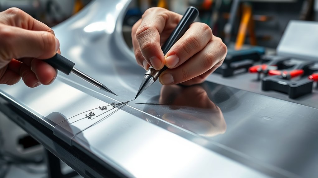
Shape the patch so its contour matches the surrounding panel before you trim the final edges. A flat patch forced into a curved opening will spring out of alignment and create stress at the seam.
Tools for Accurate Scribing
- Carbide scriber or fine-tip marker
- Straightedge and flexible ruler
- Contour gauge or cardboard template
- Body hammer and suitable dolly
- Sheet-metal shears, aviation snips, nibbler, or controlled cutoff tool
Overlap the patch only while marking if that method helps you transfer the opening accurately. Remove the patch before making the final cut so you do not accidentally cut or distort both layers.
Trim for a Small, Even Joint
Test the patch repeatedly and remove only a small amount of metal each time. For an approved butt joint, aim for a small and consistent joint that suits the process, wire, and panel thickness. Avoid wide gaps that require extra filler metal and heat.
Some OEM procedures require a lap joint, plug weld, weld bond, brazed joint, or factory-seam replacement instead. Do not convert one joint type into another because a butt seam looks easier to finish.
Clean and Align the Edges
Deburr both edges and remove rust, paint, adhesive, primer, and sealer from the fusion area. Clean both sides where you can reach them. Keep the patch flush with the original panel and verify the body line before welding.
Pro Tip: Spend more time on fit-up than on welding. A patch that follows the original contour and holds itself close to the opening needs fewer corrections, less filler metal, and less grinding.
Choose MIG or TIG Before You Start Welding
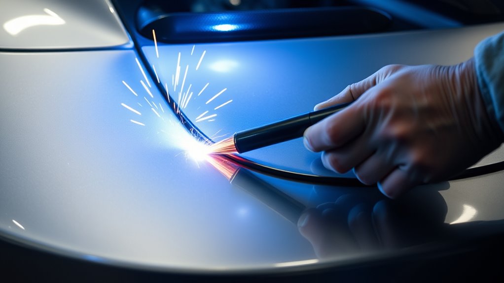
MIG and TIG can both join thin mild steel, but you must choose the process before tack welding. The approved OEM attachment method comes first.
Products Worth Considering

FIVE PROCESSES, ONE MACHINE FOR EVERY JOB - Pulse MIG, SPOT, Flux Core, Lift TIG and Stick in a single 140A welder. Pulse mode smooths the arc for less spatter, and SPOT mode pulses on a timer so thin auto body panels weld without burn-through or warping. Synergic control matches current to wire speed automatically, with no guesswork. The clear digital display shows your settings while you work. One machine replaces three

Wires diameter :0.6-1.0mm(0.023‘’-0.04‘’)

Compatible Welder Models: this compatible with KP1939-1 replacement kit is designed for use with 170A flux core welders; Before ordering, please confirm your welder uses the KP1939-1 nozzle interface by checking your welder manual or comparing the nozzle size with our product images
When MIG Makes Sense
Short-circuit MIG is a common choice for an approved mild-steel body patch. It is fast, easy to tack with one hand, and practical when rear access is limited. Small solid wire and argon-rich shielding gas can improve control and reduce spatter.
Use the push technique when it gives you a clear view of the joint and the welder or procedure recommends it. Maintain a consistent gun angle and stickout. Do not wave the gun across a thin seam or hold the arc in one place while trying to fill a large gap.
When TIG Makes Sense
TIG can provide precise control on clean, closely fitted, OEM-approved mild-steel patches. It requires two-handed control, excellent cleanliness, and more access around the joint. A poor fit can force you to add heat while filling the gap.
For ordinary steel TIG work, direct current electrode negative, argon shielding gas, a small suitable tungsten electrode, and thin matching filler wire are common starting choices. Do not apply that setup to aluminum or an unknown alloy. Follow the welder, filler-metal, and vehicle-maker instructions.
Why Flux-Core Is Usually a Poor First Choice
Self-shielded flux-core wire often produces more spatter, smoke, cleanup, and heat than gas-shielded solid wire on visible light-gauge panels. It can make burn-through and surface finishing harder for a beginner.
Flux-core can still have valid uses when its classification, machine, material, and procedure match the job. Read the guide to welding thin metal with flux core before deciding whether it suits your specific repair.
Step 3: Clamp and Tack the Patch
Hold the patch flush with the surrounding panel using sheet-metal clamps, butt-weld clamps, magnets, temporary fasteners, or a combination that does not block your weld sequence.
Place a few widely separated locating tacks around the seam. Do not immediately fill the spaces between them. First, remove or reposition the clamps as needed and check:
- The patch remains flush
- The joint has not opened or closed unevenly
- The body line and curvature still match
- The tacks have fused into both edges
- No hidden material has started to smoke or burn
If the panel moves, stop and correct it now. Grinding out a small locating tack is easier than repairing a fully welded, distorted panel.
Step 4: Close the Seam With a Skip-Tack Sequence
Do not run one continuous bead along a thin cosmetic panel. Build the seam with individual tacks or very short welds, depending on the approved procedure and your test results.
Use the Correct Weld Sequence
- Start with the locating tacks that hold the patch in position.
- Add a new tack in a distant, cool part of the seam.
- Move to another distant area rather than welding beside the last hot tack.
- Allow the panel to cool between welds.
- Check alignment and correct small changes before adding more heat.
- Continue filling the spaces until the required seam is complete.
On a cosmetic butt seam, many technicians close the joint with a series of overlapping tacks rather than long stitch beads. Each tack should fuse into the edges and the previous weld without leaving a pinhole.
Minimize Heat Distortion
Distortion comes from uneven expansion and shrinkage. Short arc time helps, but fit-up, bead size, weld sequence, machine settings, and grinding heat matter too.
- Use matching scrap to confirm the settings before welding the panel.
- Keep the joint small and consistent.
- Use the shortest weld that gives complete fusion.
- Move around the seam.
- Keep the wire stickout and torch distance steady.
- Do not pile weld metal over a cold, unfused bead.
- Do not quench the hot panel with water.
- Stop if the panel starts pulling out of shape.
A setting that is too hot may blow holes or enlarge the heat-affected area. A setting that is too cold may produce a tall bead that sits on the surface without proper tie-in. Adjust voltage and wire speed together according to the machine instructions.
Pro Tip: Watch the panel, not just the arc. Recheck the reflection, contour, and body line throughout the weld sequence so you can correct movement before it becomes a large low or high spot.
Step 5: Grind and Smooth the Weld Carefully
Inspect the completed seam before grinding. Look for cracks, visible pinholes, porosity, missed sections, and areas that did not tie into both panel edges. Check the reverse side where access allows.
Repair defects while the weld is still visible. Grinding first can hide the shape of a cold weld or make a weak area even thinner.
- Knock down only the excess: Use a suitable grinding or sanding disc with light pressure.
- Work in short passes: Long grinding passes can heat and warp the panel.
- Keep the tool flat and controlled: Avoid cutting a groove beside the weld.
- Leave sound metal: Do not chase a perfectly invisible seam by thinning the original panel or weld below a safe level.
- Finish with finer abrasives: Remove deep scratches before applying the specified coating system.
A hard grinding wheel can remove material quickly, but it is easy to gouge light sheet metal. A controlled sanding disc or file may give you better feedback near the final surface.
Step 6: Inspect and Correct the Repair
After the weld is close to flush, inspect the panel under a straightedge and reflected light. Run a clean hand over the surface only after it has cooled and all sharp edges have been removed.
Check the Weld
- No cracks or open pinholes
- No loose slag or trapped contamination
- No obvious unfused edges
- No excessive undercut beside the seam
- No areas ground thinner than the surrounding panel
- Required plug welds, tacks, or seam sections are present
Correct High and Low Spots
Use a hammer and dolly only when you understand which side to support and how the metal has moved. Light planishing can level a cosmetic seam, but uncontrolled hammering can stretch the panel and create a larger oil-can area.
If you cannot reach the rear side, use a suitable bodywork method rather than repeatedly heating, grinding, or striking the outer surface. Stop if the repair is moving farther from the original contour.
Step 7: Prepare the Surface and Restore Corrosion Protection
Welding and grinding remove factory coatings from the face, rear surface, flanges, and nearby heat-affected area. The repair is not complete until you restore the required corrosion protection.
I-CAR’s corrosion-protection guidance states that repair work can create corrosion hot spots and that the body repair manual should be checked before, during, and after the repair.
- Remove residue: Clean grinding dust, welding residue, oils, and approved-cleaner residue from the repair.
- Apply the specified primer: Use the OEM and refinishing-system procedure for bare steel. Do not assume every seam sealer or filler should be placed directly on bare metal.
- Refine the shape: Apply body filler only after the metal is sound, shaped, cleaned, and prepared according to the filler and coating system.
- Restore seam sealer: Match the original location, shape, and coverage where the repair procedure requires it.
- Restore underside protection: Replace stone-chip or underbody coatings in repaired wheelhouses and lower-body areas.
- Protect enclosed areas: Apply the specified cavity wax or corrosion inhibitor to the back side and enclosed sections after the coating sequence allows it.
- Protect access holes: Refit approved plugs and grommets, and do not block drains.
Use weld-through primer only where the OEM procedure and product instructions call for it, usually on prepared mating flanges that will become inaccessible. Applying too much can interfere with the welding process. Do not treat weld-through primer as a replacement for the final coating and cavity-protection system.
Note: Primer, seam sealer, filler, and cavity wax have different preparation and application requirements. Follow the complete product system instead of mixing steps from unrelated brands.
Common Welding Problems and How to Solve Them
| Problem | Likely Causes | What to Do |
| Burn-through | Large gap, too much heat, long arc time, slow travel, or thin rust-damaged edge | Stop, let the panel cool, correct the gap, confirm solid metal, shorten the weld duration, and retest the settings on scrap |
| Warping or oil-canning | Too many nearby welds, long beads, heavy grinding, poor initial contour, or excessive bead size | Stop adding heat, allow cooling, reassess the contour, and use a wider skip pattern with smaller weld deposits |
| Porosity | Dirty metal, paint or sealer, weak gas coverage, wind, leaks, excessive stickout, or contaminated wire | Remove the defective weld, clean both sides, check gas delivery and nozzle condition, block drafts, and review MIG welding problems and solutions |
| Tall, cold-looking bead | Insufficient voltage, excessive wire feed for the voltage, poor work-clamp connection, or incorrect technique | Do not grind it flat and assume it is sound. Correct the connection and settings, then make and inspect another scrap test |
| Wire stubs into the panel | Wire speed too high for the voltage, poor contact tip, unstable feed, or incorrect gun distance | Check the drive roll, liner, contact tip, tension, polarity, wire speed, and stickout |
| Pinholes after grinding | Spaces between tacks, porosity, contamination, or grinding into an incomplete seam | Clean the defect, make a controlled repair tack, inspect it, and grind only after it has fused correctly |
When Not to DIY the Repair
Use a qualified collision-repair technician when any of these conditions apply:
- The repair involves a frame rail, pillar, rocker reinforcement, roof rail, apron, suspension mount, seat mount, seat-belt mount, or airbag-related area.
- The OEM does not provide a sectioning or repair procedure for the damaged location.
- The panel contains HSS, UHSS, hot-stamped steel, aluminum, magnesium, carbon fiber, or an unidentified material.
- The procedure requires resistance spot welding, MIG brazing, weld bonding, self-piercing rivets, flow-form rivets, or calibrated structural equipment you do not have.
- The repair is near a fuel tank, fuel vapor, high-voltage battery, orange high-voltage cable, or damaged electrical system.
- The vehicle needs structural measurement, pre-repair scanning, post-repair scanning, calibration, or restraint-system work.
- You cannot inspect or protect the rear side of the weld.
- Your test welds do not show reliable fusion on matching material.
Warning: Do not make an unsupported structural repair and plan to have it inspected afterward. The material, cut location, attachment method, equipment, and corrosion protection must be correct from the beginning.
Frequently Asked Questions
What is the best way to weld auto body panels?
Start by checking the OEM body repair procedure and confirming that the panel is an approved mild-steel repair. Shape and trim the patch for an even fit, make test welds on matching scrap, add isolated locating tacks, and close the seam in a skip pattern. Inspect the weld before grinding and restore all removed corrosion protection.
What kind of welder do I need for body panels?
A short-circuit MIG welder with good low-end control is a common choice for an OEM-approved mild-steel patch. TIG can work on clean, closely fitted mild steel when the procedure allows it. Modern collision repairs may instead require resistance spot welding, MIG brazing, adhesive, or rivets.
Is MIG or TIG better for auto body panels?
MIG is usually faster and easier for tack-by-tack patch work, especially when access is limited. TIG gives precise control on clean, tight-fitting metal but requires more skill and access. Neither process is automatically correct for every vehicle, so follow the approved attachment method.
Is it better to weld or glue body panels?
Use the method stated in the OEM procedure. Some seams are welded, some are bonded, and some use weld bonding or rivet bonding. Do not replace a specified weld with adhesive or weld through adhesive unless the repair procedure and adhesive maker allow that exact application.
How do you prevent warping when welding auto body panels?
Begin with a correctly shaped patch and an even joint. Use small weld deposits, move to distant areas of the seam, allow cooling time, and avoid long beads. Heavy grinding can also warp the panel, so use light, short passes when finishing the weld.
What MIG wire and gas should I use for mild-steel body panels?
For an approved light-gauge mild-steel repair, .023 or .024-inch ER70S-6 solid wire with 75% argon and 25% carbon dioxide is a common starting setup. Use electrode-positive polarity for solid wire. Confirm the wire, gas, and settings with the welder chart, wire instructions, and repair procedure.
Can I use gasless flux-core wire on body panels?
Gasless flux-core wire is usually harder to control on visible light-gauge panels because it can create more heat, smoke, spatter, and cleanup. Gas-shielded solid wire is commonly easier for cosmetic mild-steel patch work. Use flux-core only when the wire, machine, material, and approved procedure match the job.
Should I disconnect the battery before welding on a vehicle?
Follow the vehicle maker’s complete power-down procedure. Many procedures require battery disconnection and additional precautions for electronic modules, airbags, capacitors, multiple batteries, hybrids, or EV systems. Place the welding work clamp on clean metal close to the weld, but do not treat clamp placement as a substitute for the OEM procedure.
Conclusion
Clean metal, close fit-up, and controlled heat remain the foundations of good auto body welding, but the repair must begin with the correct vehicle information. Confirm the panel material, approved cut location, joint design, and attachment method before you remove any metal.
For an approved nonstructural mild-steel patch, shape the panel carefully, verify your settings on matching scrap, build the seam with isolated tacks, and inspect the weld before grinding. Finish by restoring every coating and corrosion-protection layer removed during the repair.
Stop and use a qualified collision-repair technician when the repair involves structural material, restraint systems, fuel hazards, high voltage, an unsupported sectioning location, or equipment you do not have. A safe repair must restore more than appearance. It must also preserve the vehicle’s intended strength, corrosion resistance, and crash performance.
Sources
- I-CAR: Factory Built vs. Repair Procedure — explains why OEM repair attachment methods may differ and why some HSS and UHSS parts cannot use conventional GMAW.
- I-CAR: Corrosion Protection Inspection During the Repair Process — supports restoration of seam sealer, cavity wax, adhesives, and other corrosion-protection materials.
- Honda Body Repair Service Information — shows that steel welding and repair procedures vary with tensile strength and vehicle construction.
- OSHA 29 CFR 1910.252 — welding PPE, ventilation, coatings, and zinc-bearing material requirements.
- NIOSH: Welding Fumes and Fume Extraction — health risks and control considerations for welding fumes from coated and alloyed metals.
- Miller: MIG Basics for Automotive Welding Repair — wire size, shielding gas, settings, stickout, technique, and heat-control guidance for automotive welding.




