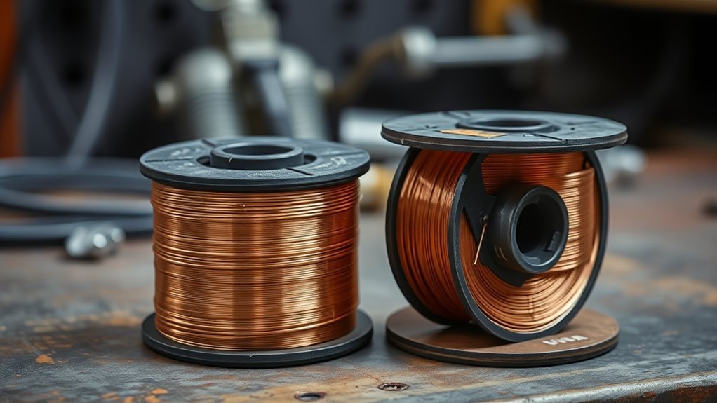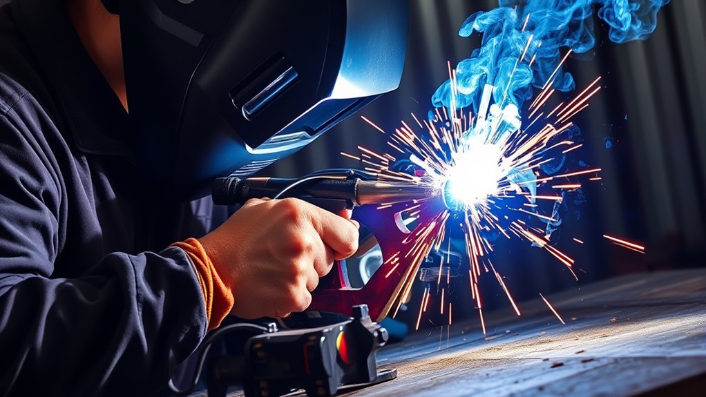
Welding a control arm is not a routine automotive repair. An original-equipment control arm is a highly stressed suspension part, and changing its metal, shape, or heat treatment can affect steering, braking, alignment, and vehicle stability. The safest default is to replace a damaged factory arm unless the vehicle manufacturer publishes a specific repair procedure. Welding is mainly appropriate for approved brackets or purpose-built fabricated arms designed for welded construction.
Quick Answer
Do not weld an original-equipment control arm unless the vehicle maker explicitly permits it and provides a repair procedure. Replace cracked, bent, heavily corroded, cast, forged, heat-treated, aluminum, or unidentified arms. Welding is appropriate mainly for approved brackets or purpose-built fabricated arms, using a qualified welder, documented procedure, fixturing, and inspection.
Key Takeaways
- Treat a damaged factory control arm as a replacement item unless the exact OEM service information authorizes welding.
- Do not apply universal voltage, wire-speed, bead-length, filler-metal, or preheat settings to an unknown suspension part.
- A custom fabricated arm needs known material, an engineered joint design, a documented welding procedure, accurate fixturing, and a qualified welder.
- Visual appearance alone cannot prove that a structural weld has adequate fusion or is free of hidden cracks.
- After an approved repair or fabrication, inspect the welds, restore corrosion protection, install hardware to OEM instructions, and complete a wheel alignment.
At a Glance
| Time Required | No universal estimate. Service-information review, removal, fixturing, welding, controlled cooling, inspection, installation, and alignment can take several separate work stages. |
| Difficulty | Expert or professional only. This is not a beginner welding project for a road vehicle. |
| Tools Needed | OEM service information, measuring tools, a rigid fixture or jig, suitable welding equipment, PPE, temperature-control tools when specified, weld-inspection tools, and alignment equipment. |
| Cost | Varies by vehicle, replacement-part price, fabrication, inspection, and alignment. Do not choose welding only because it appears cheaper than replacement. |
Warning: Do not drive on a cracked, bent, heavily corroded, or questionably welded control arm. Do not weld a factory arm merely because the metal appears to be steel. Some roadworthiness standards treat welded repairs or excessive heat on highly stressed suspension components as unsafe modifications.
Understanding Control Arm Functionality in Suspension Systems
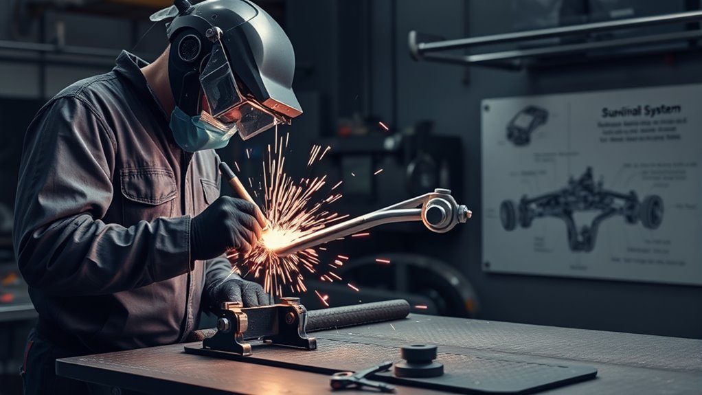
Control arms connect the vehicle chassis or subframe to the steering knuckle or wheel assembly. They guide wheel movement while helping maintain camber, caster, toe, and track position as the suspension travels. A front or rear control arm can therefore influence ride quality, steering response, braking stability, tire wear, and handling.
A typical assembly may include a stamped, tubular, cast, or forged arm body, bonded rubber or spherical bushings, and a separate or integrated ball joint. Those parts experience repeated bending, impact, braking, cornering, and fatigue loads. A repair that changes the arm’s geometry or material properties can move the wheel away from its intended path even when the weld looks smooth.
Material identification matters. Steel, cast steel, cast iron, and aluminum do not share one repair method. General techniques such as preheating cast iron should never be transferred to a control arm unless the arm’s material and an approved procedure specifically require them.
A clean bead is not proof of a safe suspension repair. The metal, joint design, heat input, geometry, procedure, and inspection all matter.
Can You Weld a Control Arm?
Sometimes, but the answer depends on what the part is and who approved the work. Separate these situations before you plan any welding:
| Part or Condition | Safe Default | Reason |
|---|---|---|
| Cracked, bent, or corroded OEM control arm | Replace it | The original material, forming, heat treatment, and fatigue life may not be recoverable through a field repair. |
| Cast, forged, heat-treated, aluminum, or unknown arm | Do not weld without explicit engineering and manufacturer approval | Heat can change strength, hardness, residual stress, and crack resistance. |
| OEM bracket, mount, subframe, or chassis area | Follow the exact OEM bulletin or service procedure | An approved bracket repair does not automatically authorize welding the control arm itself. |
| Purpose-built tubular or plate control arm | Use the designer’s drawings, material specification, WPS, fixture, and inspection plan | A fabricated arm can be designed for welded construction, but it still needs controlled engineering and production. |
For a street-driven vehicle, first check the service information for the exact year, make, model, trim, and suspension option. The UK Driver and Vehicle Standards Agency, for example, lists welded repairs and excessive heat among unsafe modifications to highly stressed suspension components. Local laws differ, but the principle is useful everywhere: roadworthiness rules can be stricter than a weld’s appearance alone suggests.
Before You Begin Welding Control Arms
Do not start by choosing a process or filler wire. Start with a repair decision. Confirm whether the manufacturer permits the work, whether the damaged item is the arm or a separate mounting bracket, and whether replacement is available.
- Locate the exact OEM procedure. Search by VIN or the complete vehicle configuration. A procedure for a different model, model year, or bracket is not transferable.
- Identify the part and material. Record whether it is stamped steel, tubular steel, cast, forged, aluminum, or a mixed-material assembly. If you cannot verify the material, do not guess.
- Measure before disassembly. Record center-to-center dimensions, bracket positions, bushing-axis alignment, ball-joint location, and any service-manual datum points.
- Inspect the full load path. Check the arm, subframe, mounts, knuckle, ball joint, bushings, fasteners, wheel, and tire. A collision or curb strike can damage more than one part.
- Check legal, warranty, and insurance consequences. A welded suspension part may affect roadworthiness, warranty coverage, inspection results, or liability.
- Choose a qualified professional. Structural suspension fabrication needs more than basic welding ability. The welder must be able to follow and document the required procedure.
Remove bushings, rubber parts, grease, paint, undercoating, and other heat-sensitive items only when the approved procedure calls for disassembly. Do not weld near a sealed ball joint, brake hose, fuel line, battery, airbag wiring, electronic module, or flammable coating. Follow the vehicle maker’s battery, restraint-system, and welding-ground precautions.
Estimated total time: There is no reliable universal 2-to-4-hour estimate. An approved job can require service-information research, removal, cleaning, measurement, fixturing, procedure setup, practice coupons, welding, cooling, inspection, coating, installation, torque procedures, and alignment.
What You’ll Need
- Vehicle-specific OEM service information or an engineer-approved fabrication drawing
- Documented base material and compatible bracket or tube material
- A welding procedure specification that covers the process, filler, joint, position, thickness, heat input, and temperature limits
- Welding machine and consumables that match the approved procedure
- Rigid fixture or jig, clamps, stops, and a flat layout table
- Calipers, angle gauges, straightedges, templates, and other measuring tools
- Angle grinder, wire brush, carbide burrs, and cleaning materials permitted by the procedure
- Infrared thermometer, contact thermometer, or temperature crayons when the procedure sets temperature limits
- Welding helmet, gloves, jacket, eye protection, hearing protection, suitable respiratory protection, and ventilation
- Visual inspection tools and any specified nondestructive testing equipment
Step-by-Step Decision and Professional Workflow for Welding Control Arms
The steps below describe a safe professional workflow, not universal DIY welding settings. If the OEM does not authorize repair of the arm, stop and replace it. For a purpose-built fabricated arm, follow the designer’s drawing and qualified welding procedure.
Preparation and Setup
- Inspect the control arm first. Look for cracks, severe rust, bends, damaged bushing eyes, distorted ball-joint mounts, previous repairs, and heat discoloration. Reject damage outside the approved repair scope.
- Confirm written authorization. Keep the OEM procedure, approved service bulletin, or engineering drawing at the workstation.
- Remove and isolate the part. Do not use the vehicle as a welding fixture. Protect or remove bushings, boots, bearings, sensors, hoses, wiring, coatings, and other heat-sensitive parts as instructed.
- Clean every weld area. Remove oil, paint, rust, undercoating, plating, and dirt far enough from the joint to prevent contamination and fumes. Reach clean metal without thinning the parent material.
- Verify material and thickness. Match the approved process, filler, shielding gas, polarity, joint preparation, and temperature limits to the documented base metal.
- Fixture the assembly. Hold the bushing axes, ball-joint location, tube centerlines, and brackets in a rigid jig. Record measurements before tacking.
- Make balanced tack welds. Use the tack size, position, and sequence stated in the procedure. Recheck every critical dimension before production welding.
- Make and evaluate practice welds. Use representative material, thickness, joint design, position, and backing. Inspect or test the coupons to the procedure’s acceptance criteria.
- Weld to the documented sequence. Control starts, stops, interpass cleaning, travel speed, heat input, and distortion exactly as required. Do not invent a universal bead length.
- Cool as specified. Do not quench unless the approved procedure requires it. Keep the assembly in the fixture until it reaches the stated release temperature.
- Inspect before coating. Check dimensions, weld profile, undercut, overlap, arc strikes, cracks, porosity, incomplete fusion indicators, and heat damage. Complete any specified NDT.
- Document the result. Record the procedure, welder, consumables, settings, temperature readings, inspection results, and final dimensions.
Pro Tip: Measure the arm from fixed bushing and ball-joint datums before tacking, after tacking, after welding, and after cooling. Distortion that is small on the bench can still create a major alignment problem on the vehicle.
Organize your tools and materials before work begins. A multiprocess welding machine, including a shop unit such as an XMT 350, may support MIG, TIG, flux-core, or stick processes. Machine capability does not approve a suspension repair, select the filler, or replace a qualified welding procedure.
Do not use a blanket target temperature range. A range such as 204°F to 300°F can appear in unrelated steel procedures, but it is not a default preheat for control arms. Some suspension manufacturers specifically warn that heat can reduce component strength. Preheat, interpass temperature, and cooling requirements must come from the applicable procedure.
Short or staggered beads can reduce local heat buildup in some approved bracket repairs, but there is no universal 3-to-4-inch control-arm rule. One manufacturer bulletin may call for 1-inch stitch welds on a chassis reinforcement, while another component may prohibit welding entirely. Follow the exact sequence for the exact part.
Welding Techniques Overview
Good welding techniques support strong, reliable joints, but technique must operate inside an approved procedure. Focus on clean metal, controlled fit-up, stable parameters, correct torch or electrode angle, proper stick-out length, interpass cleaning, and distortion control.
Use this high-level process for an approved steel bracket or purpose-built fabricated arm:
- Verify the drawing, material, joint preparation, and acceptance criteria.
- Clean the components without reducing required thickness.
- Fixture and measure the assembly before tacking.
- Prepare and evaluate representative practice coupons.
- Apply preheat only when the procedure requires it.
- Tack gussets, tubes, or side plates in the specified sequence.
- Weld within the WPS ranges for process, filler, position, thickness, gas, polarity, and heat input.
- Allow controlled cooling, then inspect dimensions and weld quality before finishing.
Settings near 21.5 volts and 471 inches per minute with .035-inch wire may work in a particular shop test, but they are not a safe starting point for an unknown control arm. Machine calibration, transfer mode, wire classification, shielding gas, joint gap, position, thickness, and base-metal chemistry can change the required settings. Use the approved WPS and practice coupon instead.
Choosing the Right Materials for Welding Control Arms and Brackets
When selecting materials for welding control arms or brackets, focus on traceable material properties, compatible strength and ductility, fatigue performance, and the designer’s required joint. A plate that is merely thick enough is not automatically suitable.
Control arm brackets are sometimes made from 1/4-inch steel, and axle tubes can be around 1/2 inch thick in some custom applications. Those dimensions are examples, not standards. The correct plate, tube, weld size, and sequence depend on the design loads, material grade, tube wall, joint geometry, and fatigue analysis.
Select the welding process and filler from the approved material specification, joint design, thickness range, access, service load, and inspection plan. Do not choose MIG, TIG, stick, or flux-core only because it is familiar.
Keep all materials clean and traceable. Contamination can contribute to porosity, poor fusion, inclusions, and cracking. You also need the mechanical properties of the steel, including whether it was cast, forged, normalized, quenched and tempered, or cold formed.
Wire such as ER70S-6 mild steel is common for compatible carbon-steel fabrication, but it is not a universal control-arm filler. Match the filler classification and strength to the documented base metal and qualified procedure.
Note: A magnet, spark test, appearance, or grinder feel cannot reliably identify every suspension alloy or heat treatment. When material records and manufacturer guidance are unavailable, replacement is safer than experimental welding.
Must-Have Tools for Welding Control Arms
Professional control-arm work needs tools that protect alignment, verify the procedure, and support inspection. A reliable welding machine is only one part of the setup.
For a purpose-built aluminum assembly, a spool gun may improve wire feeding. It does not make an unknown cast or heat-treated aluminum control arm repairable. Many aluminum suspension parts should be replaced unless the manufacturer or designer provides a qualified repair procedure.
Use these core tools when the approved job calls for them:
- Welding machine for the process listed in the WPS
- Spool gun only for a qualified aluminum GMAW procedure
- Carbide burrs and abrasives approved for joint preparation
- Correct, dry, traceable welding wire or electrodes
- Calipers, angle gauges, templates, and straightedges
- Rigid clamps, hard stops, and a dimensionally stable fixture
- Infrared or contact temperature tools when temperature limits apply
- Gas-flow meter, wire-speed verification, and machine checks where required
- Good lighting, magnification, weld gauges, and NDT supplies specified by the inspector
No single voltage or wire-speed setting fits every arm. Test on a representative coupon and record the result. Also, conduct regular equipment inspections so damaged leads, poor grounds, gas leaks, and worn consumables do not undermine the procedure.
Keep tools clean and separated by material when cross-contamination could matter. Good organization saves time, protects consumables, and makes it easier to document the work.
Products Worth Considering
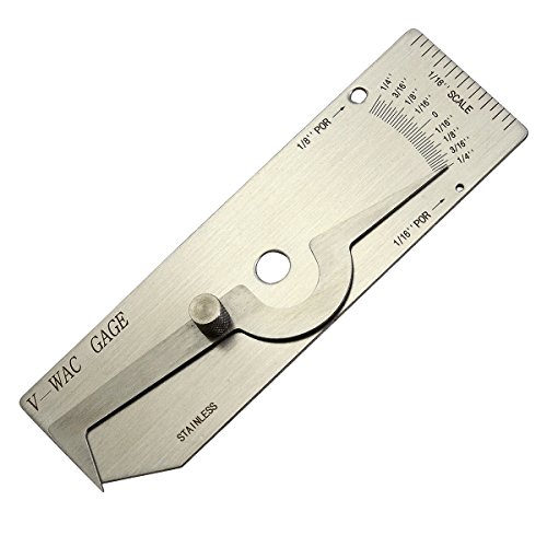
V-WAC Single Weld Gage
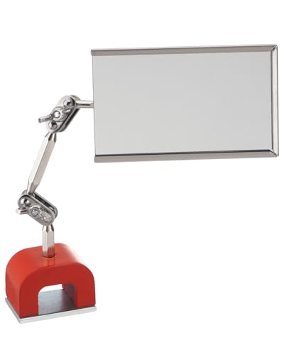
Magnetic Base: The inspection mirror frees your hands for precision work and ensures stability during critical inspections. Remove protective plate to use. Attach protective plate when not in use.

Package Includes: you will receive 3 piece welding measuring tools, including 1 piece single fillet weld depth gauge measured 4.72 x 1.26 inches/ 12 x 3.2 cm in length and width, 0.04 inches/ 1 mm in thickness, 1 piece 7 piece fillet weld gauge set measured 4.33 x 1.26 inches/ 11 x 3.2 cm in length and width, 0.31 inches/ 8 mm in thickness, and 1 piece bridge cam welding gauge measured 3.94 x 2.76 inches/ 10 x 7 cm in length and width, and 0.51 inches/ 1.3 cm in thickness
How to Prepare Your Workspace for Welding
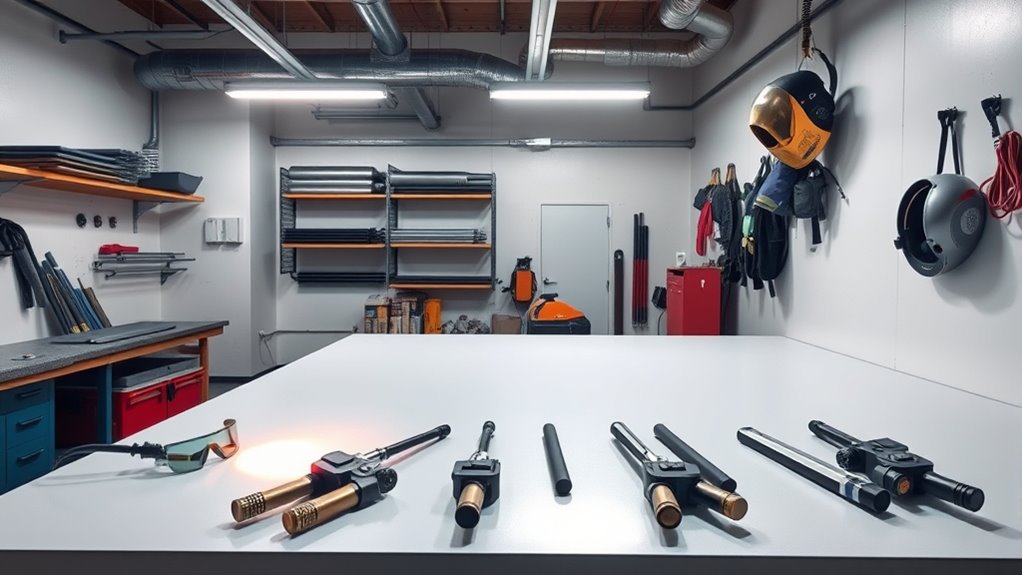
Start with a clean workspace so dirt, oil, loose debris, and grinding dust do not contaminate the weld or hide defects. Move combustible materials away from sparks, hot metal, and slag. Keep suitable fire protection ready.
Provide ventilation that controls fumes without blowing away shielding gas. Remove paint, undercoating, plating, and sealers according to the applicable safety data and procedure. Never assume a coating is harmless when heated.
Organize tools and materials so you can reach them without releasing the fixture or stepping over leads. Use a layout table or purpose-built jig for alignment. General gasless MIG welding information may help explain process limits, but it is not approval to weld an aluminum control arm without shielding gas or a qualified procedure.
Clean Workspace Essentials
A clean and organized workspace improves welding quality, fire safety, measurement accuracy, and inspection. Prepare it with these essentials:
- Clean components and the fixture before setup.
- Use adequate local exhaust or mechanical ventilation for the material and coating involved.
- Work on a nonflammable, stable welding surface.
- Remove nearby fuel, solvent, upholstery, paper, and other combustibles.
- Keep a welding helmet, safety glasses, gloves, jacket, hearing protection, and respiratory protection within reach.
- Route leads and hoses to prevent trips, abrasion, heat damage, and accidental movement of the fixture.
- Keep a fire extinguisher and post-work fire-watch plan appropriate to the shop.
Organize Tools Efficiently
A well-organized workspace improves welding efficiency and helps protect control-arm dimensions. Place the welder, clamps, gauges, filler metal, and safety gear within easy reach. Group components by material and job, then label them to prevent mix-ups.
Use a dedicated area for cleaning tools because clean metal supports better weld quality. Keep a covered waste container nearby so scraps and grinding dust do not crowd the work area. Use a written checklist for procedure revision, material identification, consumable lot, fixture measurements, temperature readings, and inspection sign-off.
| Tool/Material | Location | Purpose |
|---|---|---|
| Welder | Workbench or designated welding station | Run the approved welding process |
| Clamps and Fixture | Layout table | Secure components and preserve geometry |
| Safety Gear | Clean storage bin | Protect against radiation, heat, sparks, fumes, and noise |
| Waste Disposal Bin | Safe area away from hot work | Control debris and used cleaning materials |
Heating Techniques to Improve Welding Quality
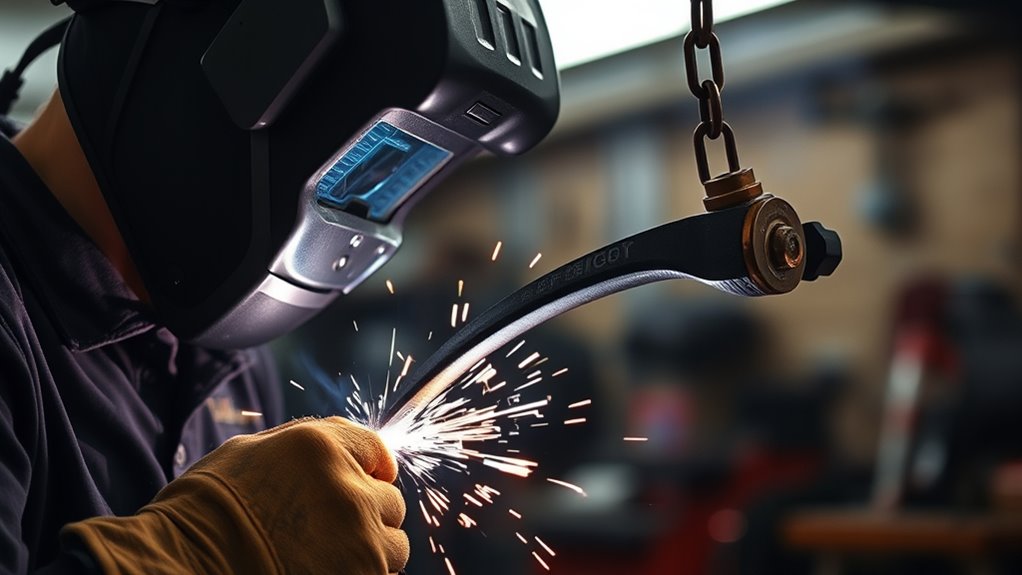
Heating the weld area can improve weld quality for some known materials and qualified procedures. Preheat may reduce cooling rate, moisture, hardness, or hydrogen-cracking risk in a suitable steel weldment. It can also weaken, distort, or damage a suspension component when used without approval.
Do not heat a control arm simply because it is thick or rusty. A manufacturer manual hosted by the National Highway Traffic Safety Administration warns that heat on certain suspension components can adversely affect their strength and contribute to loss of vehicle control. That warning is component-specific, but it shows why a universal preheat rule is unsafe.
Controlled heat is a procedure variable, not a repair trick. If the approved document does not specify preheat, interpass limits, and cooling, do not invent them.
Use these heating techniques only when the job requires them:
- Use the heating method and location specified by the WPS.
- Warm the required area evenly and avoid localized hot spots.
- Measure temperature at the specified distance and time with a suitable tool.
- Track minimum preheat and maximum interpass temperature.
- Keep heat away from rubber, seals, grease, ball-joint boots, wiring, sensors, and sealed assemblies.
- Follow the specified cooling rate and fixture-release temperature.
- Confirm proper weld sizing from the drawing or procedure rather than increasing weld size to compensate for uncertain fusion.
Note: A range such as 204°F to 300°F may fit a particular steel procedure, but it is not a standard control-arm preheat range. The exact requirement depends on verified material, thickness, restraint, hydrogen control, filler, and the approved procedure.
Which Welding Process Is Best for Control Arm Brackets?
Choose the welding process from the approved procedure after checking the material condition and thickness. Clean mild-steel brackets often use GMAW or MIG in fabrication shops, but the wire, gas, transfer mode, joint, position, and heat input still need qualification.
Stick welding with electrodes such as E6010 or E7018 can be suitable for some heavy carbon-steel fabrication. That does not make either electrode appropriate for every suspension arm, bracket, or axle housing. Electrode classification, storage, base metal, joint access, hydrogen limits, and procedure qualification all matter.
A 1/4-inch bracket joined to a 1/2-inch axle tube is a custom fabrication example, not a control-arm setting. MIG welding may be efficient when a qualified procedure covers both parts. Likewise, ER308L filler wire applies to compatible stainless work, not as a substitute for unknown suspension steel.
TIG welding offers precise control and clear visibility on suitable clean joints. It is slower and does not automatically produce a stronger joint. The weld still needs correct joint preparation, filler, penetration, heat control, and inspection.
Flux-core welding can suit some structural steel fabrication and may tolerate outdoor conditions better than gas-shielded solid wire. Wind, cleanliness, slag removal, filler classification, and procedure limits still apply. Do not select flux-core simply because the part is dirty or difficult to reach.
| Process | Possible Strength | Main Limitation |
|---|---|---|
| GMAW/MIG | Efficient and repeatable on approved clean steel fabrication | Easy to make a good-looking weld with inadequate fusion when settings or technique are wrong |
| GTAW/TIG | Fine control on suitable steel or aluminum joints | Slow, cleanliness-sensitive, and capable of excessive heat input |
| FCAW | Useful deposition rate and outdoor options for approved steel work | Slag, worm tracks, hydrogen control, and filler classification require careful management |
| SMAW/Stick | Useful for some heavy, accessible steel fabrication | Greater risk of slag inclusions, arc strikes, and poor access on small suspension parts |
Products Worth Considering

E71T-GS FLUX CORE WIRE: This self-shielding, AWS E71T-GS flux-cored wire excels due to its advanced core design, delivering exceptional arc stabilization and high feedability for effortless welding. The core also incorporates powerful deoxidizing agents, ensuring clean, reliable welds even when welding through light rust or mill scale.

E71T-GS GASLESS FLUX CORE WIRE: This AWS E71T-GS self-shielded flux-cored wire delivers smooth, stable welding without external shielding gas. It offers excellent arc stability, consistent feedability and reliable performance, allowing users to produce clean welds with minimal setup work. Its advanced flux formulation enables welding over light rust and mill scale for improved everyday practicality.

E71T-GS FLUX CORE WIRE: This self-shielding, AWS E71T-GS flux-cored wire excels due to its advanced core design, delivering exceptional arc stabilization and high feedability for effortless welding. The core also incorporates powerful deoxidizing agents, ensuring clean, reliable welds even when welding through light rust or mill scale.
Common Mistakes to Avoid When Welding Control Arms
Control-arm welding can fail because of a wrong repair decision even before the arc starts. Avoid these common problems:
- Repairing a replace-only OEM arm: Confirm manufacturer permission before planning a weld.
- Confusing a bracket procedure with an arm procedure: Approval to reinforce a frame mount does not approve welding the moving suspension link.
- Skipping material identification: Appearance alone cannot confirm alloy, forging, casting, or heat treatment.
- Skipping cleaning: Remove contamination without thinning the parent metal or spreading hazardous dust.
- Using generic settings: Do not copy voltage, wire speed, electrode, gas, or preheat from an unrelated project.
- Using poor heat control: Follow the specified sequence and temperature limits to reduce distortion and metallurgical damage.
- Ignoring alignment: Fixture and measure the arm through tacking, welding, and cooling.
- Welding over cracks or rust: Remove only defects covered by the approved repair. Replace the part when damage exceeds the procedure.
- Grinding the bead for appearance: Do not remove required throat, toe, or reinforcement. Grind only when the procedure allows it.
- Accepting uneven beads without evaluation: Monitor bead width and height, but judge the weld against documented acceptance criteria.
- Skipping post-weld protection: Bare metal can corrode quickly, especially around crevices and road-salt exposure.
Pro Tip: Use hard fixture stops and a written measurement sheet instead of relying on tack magnets alone. Magnets position parts, but they do not prove that bushing axes and ball-joint datums remain correct.
How to Assess the Quality of Your Welds
Inspect every approved weld before coating or installation. Start with bead appearance, but do not stop there. Even width and smooth tie-in can show good control, while a smooth surface can still hide incomplete fusion or subsurface cracking.
Look for visible cracks, arc strikes outside the joint, undercut, overlap, crater defects, burn-through, excessive reinforcement, poor starts and stops, and signs of porosity. I-CAR advises repairers to watch for porosity, penetration, cleanliness, and incomplete welds, to make practice welds, and to follow OEM procedures.
Use a representative coupon to verify the setup before production work. A bend, break, macro-etch, or other destructive coupon test may be required by the procedure. Do not perform an improvised load test on the finished control arm and assume it proves fatigue life.
Visual inspection should be followed by the nondestructive testing specified by the designer, OEM, or inspector. Liquid penetrant testing can reveal surface-breaking flaws in clean, nonporous materials. Magnetic particle testing can find surface and near-surface discontinuities in suitable ferromagnetic steel. A qualified inspector should select the method and acceptance criteria.
Watch for worm tracks in flux-core welds, but remember that any acceptance decision belongs to the applicable code, drawing, WPS, and inspection plan. Check the heat-affected zone for cracks, excessive grinding, local thinning, distortion, and evidence that rubber or sealed components overheated.
Post-Weld Inspection Checklist
- Final dimensions match the drawing or OEM datum points.
- No visible crack appears in the weld, crater, toe, root, or heat-affected zone.
- Weld size and length match the approved drawing.
- No unacceptable porosity, undercut, overlap, slag, burn-through, or incomplete fusion indication is present.
- No unauthorized arc strike, extra weld, drilled hole, heating mark, or ground area is present.
- Specified liquid penetrant, magnetic particle, ultrasonic, radiographic, or other NDT is complete and accepted.
- Inspection records identify the part, procedure, welder, date, and result.
Post-Weld Installation, Alignment, and Reinspection
An accepted weld is not the end of the job. Clean the part, restore approved primer, seam sealer, cavity protection, and topcoat without covering a weld before inspection is complete.
Install the arm with the exact fasteners, washers, eccentric hardware, and torque sequence specified by the vehicle maker. Replace one-time-use bolts, nuts, or alignment hardware when the service information requires it. Tighten bonded-rubber bushing fasteners at normal ride position only when the OEM procedure says to do so.
Complete a four-wheel alignment or the specified axle alignment. Verify camber, caster, toe, thrust angle, steering-wheel position, and sensor calibration as applicable. Check brake hoses, ABS wiring, tire clearance, bump travel, and full steering movement.
Use a cautious professional road test only after the vehicle passes inspection and alignment. Reinspect torque, witness marks, coating, tire contact, and the repaired area at the interval stated by the engineer or procedure. Stop driving immediately if you notice pulling, clunking, a steering change, uneven tire wear, or visible cracking.
When You Should Replace Instead of Weld
Replace the control arm when you see severe rust, section loss, a hole, a split, heavy bending, collision kinks, cracks near a ball-joint mount, a damaged bushing eye, a torn sleeve, previous unauthorized welding, or heat damage across a large section.
Also replace it when you cannot verify the material, heat treatment, geometry, repair permission, filler, or inspection criteria. Cast, forged, and heat-treated factory arms deserve special caution because a local weld can create hard zones, soft zones, residual stress, or new crack paths.
A new or approved replacement arm is often less expensive than engineering, fixturing, qualified welding, NDT, refinishing, alignment, and liability. More importantly, replacement restores a documented component rather than relying on an uncertain field repair.
Frequently Asked Questions
Can a lower control arm be welded?
A purpose-built fabricated lower control arm can be welded when its designer provides the material, joint, procedure, fixture, and inspection requirements. A cracked, bent, corroded, cast, forged, aluminum, heat-treated, or unidentified factory arm should normally be replaced unless the exact vehicle manufacturer procedure authorizes repair.
Is soldering just as strong as welding?
No. Soldering uses a lower-melting filler and does not fuse the control-arm base metal. It is not an acceptable joining method for a structural suspension component. Use an approved welded design or replace the part.
What is the golden rule in welding?
There is no single official golden rule, but a sound principle is to follow the approved procedure from preparation through inspection. Clean fit-up, correct material and filler, controlled parameters, qualified technique, and verified acceptance criteria matter more than bead appearance.
What’s the hardest welding position?
Overhead welding is difficult for many welders because gravity affects the molten pool and body position can be awkward. The hardest position varies by process, joint, access, and experience. Remove and fixture a control arm rather than attempting an unauthorized overhead repair on the vehicle.
Can you weld control arms with a MIG welder?
MIG can be used for some approved mild-steel brackets and purpose-built fabricated arms. The machine alone does not make the repair safe. The material, filler, gas, transfer mode, joint, thickness, position, heat input, welder qualification, and inspection must match the approved procedure.
Do you need to preheat control arms before welding?
Do not preheat a control arm by default. Some known steel weldments require preheat, while some suspension components can lose strength when heated. Use only the minimum, maximum, measurement method, and cooling instructions stated in the approved procedure.
Can you weld an aluminum or cast control arm?
Do not assume so. Cast and heat-treated aluminum can lose important properties in the heat-affected zone, while cast iron, cast steel, and forged steel require different procedures. Replace the arm unless the manufacturer or responsible engineer provides a qualified repair plan.
Is a visual inspection enough for a control-arm weld?
Usually not for a safety-critical fabricated arm. Visual inspection is essential, but it cannot reveal every hidden lack of fusion or subsurface crack. The drawing or repair plan should state whether liquid penetrant, magnetic particle, ultrasonic, radiographic, destructive coupon testing, or another method is required.
Safety Disclaimer: This article is for informational purposes only and does not replace vehicle-specific OEM service information, an engineered welding procedure, professional automotive advice, qualified welding, inspection, or local roadworthiness rules. Control arms are critical suspension parts. Do not repair or reinstall a welded component without written authorization and competent professional review.
Conclusion
A safe control-arm decision starts before welding. Replace a damaged factory arm unless the exact manufacturer procedure allows repair. For an approved bracket or purpose-built fabricated arm, use verified material, an engineered joint, a qualified WPS, rigid fixturing, controlled heat, documented inspection, proper corrosion protection, OEM installation procedures, and wheel alignment. When any part of that chain is unknown, replacement is the safer choice.
Sources
- UK DVSA MOT Inspection Manual, Suspension Arms and Unsafe Modifications: supports the warning that welded repairs and excessive heat can be unsafe modifications to highly stressed suspension components.
- I-CAR, Weld Inspection During the Repair Process: supports practice welds, inspection for porosity and incomplete welds, and following OEM procedures.
- OSHA 29 CFR 1910.252, Welding General Requirements: supports fire-hazard control, ventilation, and safe hot-work practices.
- American Welding Society, Standard Welding Procedure Specifications: supports using qualified procedures backed by procedure qualification records.
- American Society for Nondestructive Testing, Liquid Penetrant Testing: supports using penetrant inspection to reveal surface-breaking discontinuities in suitable nonporous materials.
- Hendrickson Suspension Service Procedure Hosted by NHTSA: provides a manufacturer example warning that heat can adversely affect suspension-component strength.