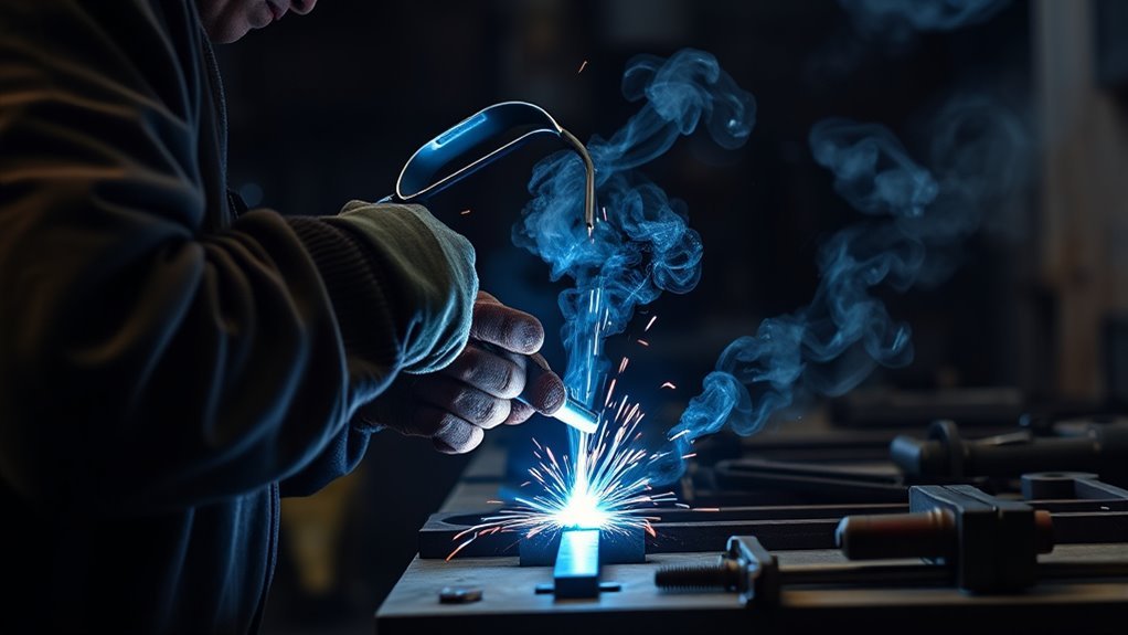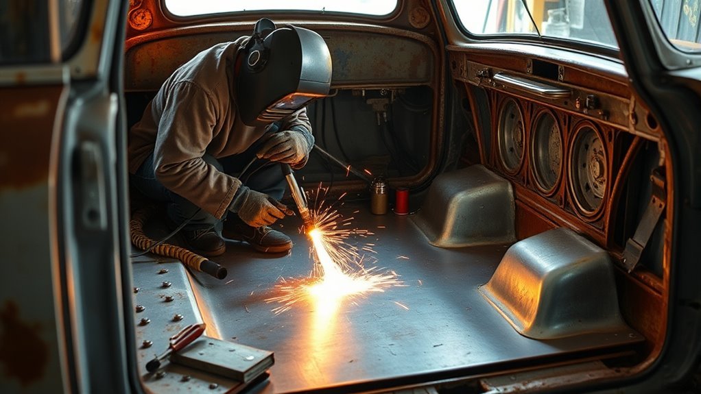
Rusty floor pans can let water, fumes, and road noise into the cabin, but the larger concern is what the damaged metal may be supporting. A floor panel can connect to crossmembers, seat mounts, restraints, or other parts of a unibody structure. A safe repair therefore starts with the exact vehicle procedure—not with a generic patch and a welder.
Quick Answer
To weld a car floor pan, first verify the VIN-specific OEM repair method, support the body correctly, remove every fire hazard, and cut back to sound metal. Test-fit the correct panel, make the specified plug or stitch welds with controlled heat, then restore primer, seam sealer, coatings, and cavity protection exactly as directed.
Key Takeaways
- Use the VIN and model year to obtain the vehicle maker’s body-repair procedure before cutting.
- Remove rust until the surrounding steel is full thickness, clean, and strong enough to weld.
- Protect fuel and brake lines, wiring, restraint parts, batteries, insulation, and hidden cavities from heat and sparks.
- Use the joint type, weld process, weld count, and corrosion products specified by the OEM.
- Make test welds on matching scrap, keep the work clamp close, and spread heat around the panel.
- After all hot work is complete, restore primer, seam sealer, underbody protection, and cavity wax in the correct sequence.
At a Glance
| Time Required | About 8–20+ working hours, often spread over one or more days for fitting, cooling, curing, and reassembly |
| Difficulty | Advanced DIY; professional repair is appropriate when structural members, seat-belt mounts, crash damage, or high-voltage components are involved |
| Tools Needed | OEM repair information, MIG or specified welder, cutting and grinding tools, measuring tools, clamps or Cleco pins, PPE, ventilation, and fire-extinguishing equipment |
| Cost | Roughly $150–$600 for a patch panel and common consumables when you already own the tools; full pans, rare parts, and professional labor can cost much more |
Warning: Do not cut or weld until you have checked both sides of the floor and followed the OEM procedures for the 12-volt battery, airbag/restraint system, and—on a hybrid or EV—the high-voltage system. Orange high-voltage cables and a traction battery beneath the floor require trained, vehicle-specific handling.
What’s in This Article
- Why Floor Pan Replacement Is Essential for Your Vehicle
- Verify the OEM Repair Procedure Before Cutting
- Preparing Your Workspace and Materials for Welding
- Essential Tools Required
- Safety Gear Importance
- Choose the Panel, Material, and Joint Design
- Step-by-Step Guide to Cutting and Fitting Replacement Panels
- Tack Welding: The Importance of Securing Your Panels
- Welding Techniques for Installing Floor Pans
- Inspect the Welds and Repair Before Sealing
- Sealing Your New Floor Pan
- Troubleshooting Common Welding Issues
- Find Resources for Enhancing Your Welding Skills
- Frequently Asked Questions
- Conclusion
- Sources
Why Floor Pan Replacement Is Essential for Your Vehicle
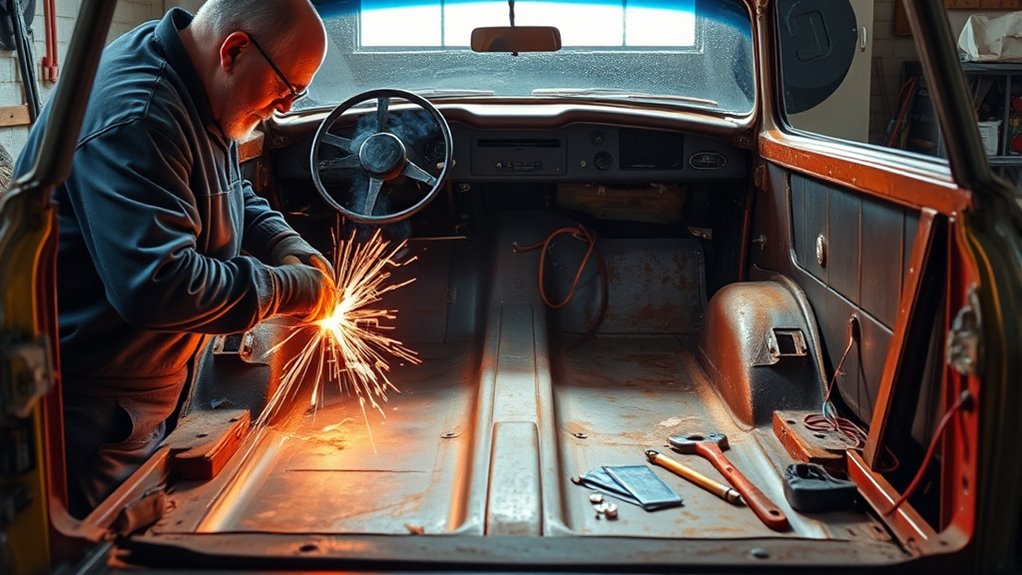
Repair a floor pan when rust has perforated the steel, a previous patch has failed, or impact damage has changed the panel’s shape or attachment. Water entering through the floor can damage carpet, insulation, connectors, and sound-deadening material. Exhaust gases may also enter through open holes, especially when the vehicle is moving or idling.
The safety effect depends on the vehicle. Some floor areas are mainly closure panels, while others connect to crossmembers, rockers, tunnel sections, seat tracks, seat-belt anchors, or battery structures. Severe corrosion around any mounting point or load-carrying joint needs a qualified collision-repair inspection.
A durable floor-pan repair restores three things: the specified attachment, the original body shape, and the corrosion protection removed during the work.
A clean repair can also improve cabin comfort and vehicle value. More importantly, it gives you a dry, sealed foundation for the carpet, wiring, seats, and other interior parts.
Verify the OEM Repair Procedure Before Cutting
Start with the complete VIN, model year, body style, and powertrain. Use them to locate the current vehicle maker’s body-repair manual or collision-repair procedure. The I-CAR OEM Information portal can help you find manufacturer resources, but the vehicle maker’s procedure remains the controlling instruction.
Confirm all of the following before you mark the cut:
- Panel material and thickness: Do not assume every floor pan is ordinary 20- or 22-gauge mild steel.
- Allowed repair boundary: Determine whether the panel must be replaced at factory seams or may be sectioned at a documented location.
- Attachment method: Check whether the repair calls for squeeze-type resistance spot welds, MIG/MAG plug welds, MIG brazing, adhesive, rivets, or a combination.
- Weld details: Record the required weld count, location, hole size, spacing, and any destructive test requirements.
- Corrosion protection: Identify the approved primer, adhesive, seam sealer, foam, underbody coating, and cavity-wax sequence.
- System precautions: Find the battery, SRS, sensor, fuel-system, and high-voltage disable instructions that apply to the repair area.
Note: A repair procedure for a different model year, body style, or powertrain may not apply. Changes in steel grade, battery placement, reinforcements, or attachment methods can alter the safe repair.
If the floor is distorted from a collision, measure the body on an approved fixture or measuring system before cutting. Bracing may be needed to hold door openings and body dimensions while a large section is removed.
Preparing Your Workspace and Materials for Welding
Work on a clean, level surface with the vehicle supported at manufacturer-approved lifting points. Use properly rated stands or a lift, and do not rely on a jack alone. Position the supports so the body stays at the dimension specified by the repair information.
Remove the seats, carpet, padding, insulation, seam sealer, undercoating, and trim far enough from the repair to expose hidden hazards. Inspect above and below the floor for fuel and brake lines, wiring harnesses, electronic modules, restraint components, exhaust parts, heat shields, refrigerant lines, and closed cavities that may contain foam or wax.
Follow the OEM battery and restraint-system shutdown instructions. I-CAR guidance for welding includes isolating both 12-volt battery cables, placing the work clamp close to the weld on the same panel, and following the vehicle maker’s procedure for SRS and high-voltage shutdown. Review the full I-CAR battery-disconnect guidance before welding near vehicle electronics.
Move combustible material away or shield it with a welding blanket. Keep a suitable extinguisher ready, assign a second person to watch the opposite side when sparks can enter hidden spaces, and inspect the area for at least 30 minutes after hot work. These precautions reflect OSHA hot-work fire-prevention requirements.
Warning: Stop immediately if you smell fuel, see smoke from a hidden cavity, or cannot protect a line, tank, battery, module, or restraint component. Do not weld in an area where flammable vapor may be present.
Products Worth Considering

✅【Fire-Resistant Carbon Felt Construction】The Matace welding blanket is made from 5mm thick carbon felt and has been tested in accordance with ASTM D6413 standards. Its dense, heavy-duty structure is designed to help manage sparks, hot slag, and radiant heat during welding and high-temperature work.

Made of Flame Retardant Fiberglass

Upgraded Reinforced Design – Unlike standard welding blankets with plain grommets, this fiberglass welding blanket comes reinforced metal grommets that resist loosening, making it more durable and stable. Each grommet is fitted with a double-sided thick black plastic washer for added strength, ensuring stronger support, more secure hanging, and flexible installation for maximum durability and safety during welding, cutting, and fire protection
Essential Tools Required
Gather the tools and materials before the first cut so you can test-fit the panel without rushing.
- Vehicle-specific repair information: Keep the procedure open where you can check cut lines, attachment points, and corrosion steps.
- Welder: Use the process and equipment required by the OEM. A properly set up MIG welder is common for older mild-steel floor repairs.
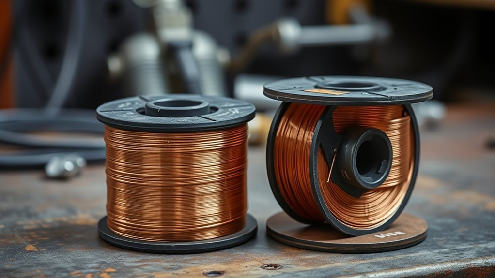
- Wire and shielding gas: Match the wire type, diameter, and gas to the machine, panel, and repair procedure.
- Cutting tools: An air saw, cutoff wheel, drill, spot-weld cutter, or nibbling tool can make controlled cuts.
- Grinding tools: Use a die grinder, belt sander, or flap disc for coating removal and careful weld finishing.
- Panel-forming tools: A punch/flanger, body hammer, dolly, and sheet-metal brake may be useful when the procedure allows a fabricated patch.
- Holding tools: Use clamps, panel clamps, self-tapping screws, or Cleco pins to hold the panel tight.
- Measuring tools: Use a tape, tram gauge, straightedge, contour gauge, and marker to preserve body and panel dimensions.
- Safety equipment: Have welding PPE, local fume extraction, welding blankets, and a suitable fire extinguisher ready.
- Finishing products: Use only the specified cleaners, primers, seam sealer, topcoats, underbody protection, and cavity wax.
Inspect the welder’s ground lead, gun liner, contact tip, drive rolls, gas hose, and regulator before use. Poor wire delivery or an unstable gas supply can ruin test welds and increase burn-through.
Safety Gear Importance
Wear a welding helmet with the correct shade, safety glasses under the helmet, flame-resistant clothing, leather welding gloves, and closed leather footwear. Add hearing and face protection when cutting or grinding.
Welding and cutting can release metal fumes, gases, and smoke from coatings, adhesives, seam sealers, and contamination. Remove coatings from the hot-work zone as the repair procedure directs and use local exhaust that pulls fumes away from your breathing zone. OSHA’s welding hazard guidance explains why ventilation and exposure controls matter.
A simple dust mask is not a universal welding-fume solution. Respiratory protection must be selected for the identified hazard, used with adequate ventilation, and fitted and maintained correctly. Never use oxygen to ventilate a work area.
Keep gas cylinders upright, secured, and away from sparks and vehicle traffic. Route welding leads so they cannot contact sharp edges, moving parts, computers, sensors, or high-voltage cables.
Choose the Panel, Material, and Joint Design
The best replacement is usually the correct service part because its shape, drain points, ribs, flanges, and mounting locations match the vehicle. A fabricated patch may be acceptable for an older non-structural area when the OEM information and local inspection rules allow it.
Match the original steel type and thickness as closely as the repair procedure requires. Do not replace high-strength or ultra-high-strength steel with generic mild steel, and do not add extra layers because they feel stronger. Added thickness can change fit, weld behavior, corrosion risk, and crash performance.
Use the specified joint:
- Factory-flange replacement: Remove the original attachment and recreate the approved welds or other fasteners at the factory seam.
- Plug weld: Use only when the procedure permits MIG/MAG plug welds in place of factory spot welds. Follow the required hole size, weld count, and spacing.
- Butt joint: Use only at an approved sectioning location. Tight fit-up is essential on thin metal.
- Lap joint: Do not treat an overlap as a universal beginner shortcut. It can trap moisture and may be prohibited unless the OEM provides an overlap or backing-plate procedure.
- Adhesive or weld bonding: Use the specified product, bead size, open time, clamping method, and weld sequence. Do not invent an adhesive-only substitution.
Pro Tip: Before trimming the new panel to its final size, mark seat tracks, drain plugs, wiring clips, reinforcements, and flange locations. A panel that looks flat can still be misaligned enough to affect reassembly.
Step-by-Step Guide to Cutting and Fitting Replacement Panels
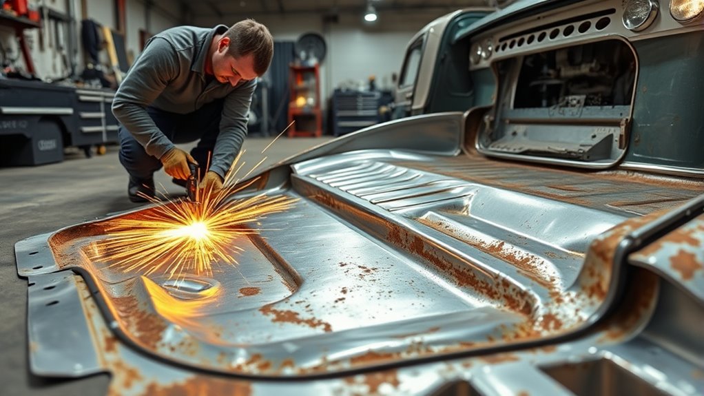
Inspect the original floor from above and below before you cut. The goal is to remove damaged metal without cutting into a reinforcement, line, wiring harness, battery enclosure, or attachment that the repair procedure says to preserve.
- Document the vehicle. Record the VIN, model year, body style, repair procedure, measurements, and pre-repair photos.
- Strip the work area. Remove interior trim, coatings, insulation, and hidden combustible material far enough to expose both sides of the repair.
- Locate every hazard. Mark fuel and brake lines, wiring, SRS parts, modules, exhaust components, and hybrid/EV components.
- Support and measure the body. Place the vehicle on approved supports, verify key dimensions, and install bracing when the procedure requires it.
- Mark the removal boundary. Follow factory seams or the documented sectioning location. Stay outside thinned, pitted steel so the remaining edge is sound.
- Cut in stages. Leave extra metal on the first pass, then trim gradually. Remove factory spot welds without excessively thinning the panel that will remain.
- Prepare the replacement panel. Compare the stamping, flanges, reinforcements, drain holes, mounts, and edges with the original part.
- Test-fit repeatedly. Trim small amounts until the panel rests in position without being forced. Check gaps, height, contour, and access to the back side.
- Confirm reassembly points. Temporarily check seat tracks, brackets, plugs, clips, and nearby trim before welding blocks access.
- Prepare attachment points. Mark plug-weld holes or other fastener locations exactly as the repair procedure specifies.
- Prepare mating surfaces. Clean the weld zone to the condition required by the OEM and product maker. Use weld-through primer only where both instructions permit it.
- Clamp the panel. Use clamps, self-tapping screws, or Cleco pins to hold the flanges in full contact, then recheck all measurements.
Good sheet-metal welding preparation reduces gaps, burn-through, and unnecessary grinding. Do not move to final welding until the panel fits correctly in a relaxed, fully clamped position.
Tack Welding: The Importance of Securing Your Panels
Tack welds lock the panel’s position before heat can pull it out of shape. Place the first tacks at widely separated points, then recheck panel height, gap, and body measurements. Correct a high edge or twist before adding more welds.
For an approved butt seam, add small tacks between earlier tacks while moving around the panel. Let each area cool before returning. For a factory flange, temporary tacks should not replace the specified plug welds or spot welds.
Keep tacks small enough to limit heat but large enough to hold the panel during inspection. A cracked tack, contaminated tack, or tack sitting on top of the metal should be removed and remade rather than buried under later welds.
Flux-cored wire can be used on some older mild-steel repairs, but it generally adds spatter and can make heat control harder on thin sheet. Review flux-core welding fundamentals and make test coupons before using it on the vehicle.
Welding Techniques for Installing Floor Pans
Start by reproducing the joint on scrap made from the removed floor and the replacement material. Include the same number of layers, flange fit, coatings, wire, gas, and access angle. Adjust the machine until the test weld has the fusion and nugget size required by the repair procedure.
For common mild-steel MIG work, a 75% argon/25% carbon-dioxide shielding-gas blend produces less spatter and is easier to control on thin sheet than straight carbon dioxide. Use the machine manufacturer’s chart as the starting point, then confirm the result on scrap. Miller’s automotive MIG guide also recommends a push technique for thin body panels.
Use these heat-control practices when they agree with the OEM procedure:
- Plug welds: Clamp the flange tightly, keep the gun angle consistent, and fill each prepared hole so the weld fuses to the lower panel and ties into the edge of the upper panel.
- Butt seams: Use separated short welds or overlapping tacks, moving around the panel until the required seam is complete.
- Skip welding: Move to a distant area instead of placing consecutive welds beside each other. This spreads heat and reduces distortion.
- Short current path: Attach the work clamp to clean metal close to the weld and, when possible, on the same panel.
- Natural cooling: Pause between welds. Do not rush the repair by laying a continuous bead on thin sheet unless the procedure expressly calls for it.
- Backing bar: A clean copper backing bar can support a butt seam and absorb heat when access and the repair procedure allow it.
Miller’s current thin-sheet welding guidance emphasizes tight fit-up, skip welding, and controlled travel to reduce burn-through and warping.
Pro Tip: Keep a written record of the successful test settings, wire, gas flow, plug-hole size, and coupon result. Recheck the coupon whenever the metal stack or welding position changes.
Inspect the Welds and Repair Before Sealing
Let the panel cool, then inspect every attachment from both sides where access permits. Compare the finished weld count and location with the OEM procedure. Look for missed welds, cracks, porosity, burn-through, edge separation, excessive grinding, and distortion.
Check plug welds for full tie-in around the hole and evidence of fusion to the lower panel. A round cap that merely fills the hole is not proof of a sound joint. Use the destructive test method specified by the OEM or training program on matching coupons before relying on the vehicle welds.
Recheck body measurements, panel contour, seat and bracket fit, drain openings, and access holes. Do not grind a structural weld below the profile allowed by the repair procedure simply to make it look smooth.
After reassembly, follow OEM requirements for a pre- or post-repair scan, restraint-system initialization, occupant-sensor calibration, battery reconnection, and warning-light checks. Do not clear a safety-system fault without diagnosing its cause.
Sealing Your New Floor Pan
Finish all welding, spark-producing grinding, and hot work before applying cavity wax, foam, or other flammable corrosion products. I-CAR warns that hidden seam sealer, foam, and cavity wax can create a fire hazard if their location and application sequence are ignored.
Use this general order only when it matches the OEM procedure and each product’s technical data sheet:
- Finish the welds carefully. Remove only sharp projections and excess weld that the procedure allows you to dress.
- Clean the repair. Remove grinding dust, oil, residue, and loose corrosion without contaminating the seam.
- Restore primer. Apply the specified epoxy, 2K primer, e-coat replacement, or other coating to the required surfaces and allow the stated flash or cure time.
- Apply seam sealer. Reproduce the OEM seam path and bead coverage. Do not block drains, threaded inserts, or service openings.
- Topcoat the repair. Restore paint, stone-chip coating, and underbody protection where required.
- Apply cavity protection last. After all hot work and refinishing are complete, fog approved cavity wax into enclosed seams as directed.
Product instructions differ. For example, the 3M Urethane Seam Sealer technical data sheet lists specific surface preparation, painting, and weld-through limits. Follow the exact data sheet for the sealer you use rather than applying a universal rule.
Seal the cabin side and underside wherever the OEM procedure calls for coverage and access allows proper preparation. After the products cure, perform a controlled water-leak check and confirm that every factory drain remains open before reinstalling dry insulation and carpet.
Troubleshooting Common Welding Issues
- Burn-through: Stop and let the area cool. Repair the hole on sound metal, reduce heat input, improve fit-up, shorten arc time, and retest on scrap.
- Little or no fusion: Remove the failed weld. Confirm clean bare metal at the weld point, full flange contact, correct work-clamp placement, and adequate machine settings.
- Porosity: Check for paint, rust, sealer, oil, drafts, poor gas coverage, a damaged nozzle, or excessive gun distance.
- Panel warping: Stop adding adjacent welds. Recheck support and measurements, spread the weld sequence farther apart, and allow full cooling between areas.
- Wide butt-joint gap: Refit the panel or add a correctly shaped patch. Do not bridge a large gap with repeated weld metal on thin sheet.
- Plug weld sitting on top: Remove it, tighten the clamp, verify the lower panel is clean, and adjust the test settings until the weld fuses both layers.
- Erratic wire feed: Inspect the spool tension, drive rolls, liner, contact tip, gun cable, wire condition, and power connection.
- Sealer lifting or cracking: Check the product’s approved substrate, cleaning method, primer compatibility, bead thickness, and cure time.
- Smoke from a cavity: Stop welding, disconnect power safely, inspect both sides, and begin fire response. Do not resume until the source is removed and the area is safe.
Note: If corrosion reaches a rocker, crossmember, frame rail, seat mount, seat-belt anchor, suspension pickup, or high-voltage battery enclosure, stop treating the job as a simple floor patch and have a qualified collision-repair professional assess it.
Find Resources for Enhancing Your Welding Skills
Begin with the vehicle maker’s repair information and current welding-equipment instructions. The I-CAR portal can help locate OEM collision information, hybrid/EV disable procedures, corrosion guidance, and partial-part replacement information.
Practice plug welds, butt seams, and heat control on scrap that matches the vehicle. Cut the coupons apart or perform the specified peel test so you can see whether the weld fused both layers. Appearance alone is not enough.
Community-college, vocational-school, and recognized collision-repair courses provide supervised practice and feedback. They are especially useful before you work near restraints, structural sections, coated steels, or high-voltage systems.
Manufacturer guides and structured welding books can build a sound base for machine setup and troubleshooting. Community forums may provide useful project examples, but compare any advice with the OEM procedure and product technical data before applying it.
Frequently Asked Questions
What Is the Best Metal for Floor Pans?
Use the OEM service panel or steel that matches the original material, thickness, shape, and coating as the vehicle procedure requires. Do not assume that 20- or 22-gauge mild steel is correct for every vehicle or every part of the floor.
Can You Weld Floor Pans With Flux Core?
Flux-core wire can join some older mild-steel floor panels, but it often creates more spatter and can be harder to control on thin sheet. Use it only when the repair procedure permits the process, and prove the settings on matching scrap before welding the vehicle.
What Welder Is Best for Car Panels?
A gas-shielded MIG welder is common for thin mild-steel automotive panels because it offers good control and relatively low spatter. The correct process is still the one listed by the vehicle maker; some repairs require resistance spot welding, MIG brazing, adhesive, rivets, or another attachment method.
How Do You Stop Floor Pan Welds From Warping?
Start with tight fit-up, use the correct low-energy settings proven on scrap, make short separated welds, and move around the panel instead of heating one area continuously. Keep the body supported correctly and allow the metal to cool before returning to the same spot.
Should You Seam Seal Both Sides of a Floor Pan?
Restore seam sealer wherever the OEM procedure shows it, including the cabin side, underside, or both. Prepare and prime each surface exactly as the sealer maker directs, and do not cover drains or apply cavity wax until every hot-work operation is finished.
How Do You Repair Car Flooring?
Remove the interior, identify and protect nearby systems, cut damaged steel back to sound metal, fit the correct panel, recreate the specified attachments, inspect the welds, and restore corrosion protection. Reinstall only dry insulation, carpet, seats, and restraint components after the repair passes its checks.
Do Floor Pan Seams Need a Continuous Weld?
Not always. Factory flanges commonly use a specified number of spot or plug welds, while an approved butt-section seam may require a continuous completed joint made through separated short welds. Follow the vehicle procedure rather than applying one weld pattern to every floor pan.
Should You Disconnect the Battery Before Welding a Floor Pan?
Yes, follow the exact OEM shutdown procedure. General collision-repair guidance calls for isolating both 12-volt battery cables and keeping the welding current path short. Hybrid and electric vehicles also require vehicle-specific high-voltage disabling by trained personnel, and some repairs require battery or module removal.
Conclusion
A strong floor-pan repair starts with the correct vehicle procedure, sound supporting metal, accurate fitment, and controlled heat. Take time to measure, protect nearby systems, test the welder on matching scrap, and inspect every attachment before hiding it under coatings.
The weld is only part of the job. Primer, seam sealer, topcoat, underbody protection, and cavity wax must be restored in the right order so moisture cannot restart the corrosion from inside the seam.
When damage reaches structural members, restraint mounts, crash-damaged areas, or a hybrid/EV battery structure, use a qualified collision-repair facility rather than improvising a patch.
Sources
- OSHA 29 CFR 1910.252: Welding, Cutting, and Brazing — fire prevention, fire watch, PPE, ventilation, and hot-work precautions
- I-CAR OEM Information — access points for vehicle-maker repair procedures and OEM-specific technical information
- I-CAR Battery Disconnect and Welding Guidance — 12-volt isolation, work-clamp placement, SRS, electronics, and high-voltage precautions
- I-CAR: When to Apply Corrosion Protection During the Repair Process — sequencing and fire risks involving seam sealer, foam, and cavity wax
- Miller: Successfully Welding Sheet Metal With MIG and TIG — fit-up, skip welding, backing bars, and heat control
- 3M Urethane Seam Sealer Technical Data Sheet — product-specific surface preparation, application, painting, and weld-through limitations