
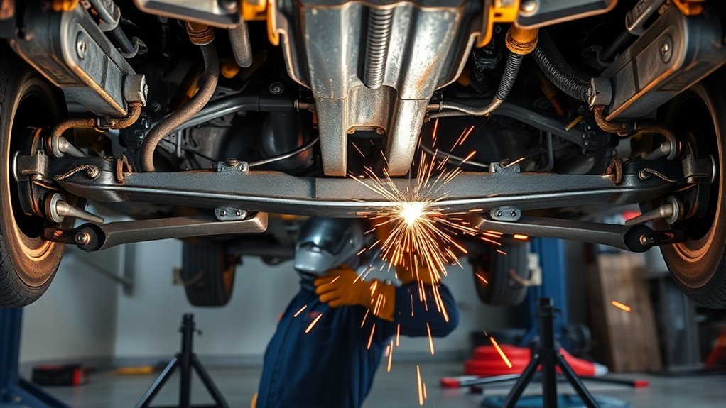
Installing a weld-in suspension crossmember is not a universal cut-and-weld job. The correct method comes from the crossmember manufacturer’s instructions and the vehicle maker’s repair information. Before trimming a rail, confirm the material, dimensions, permitted welding process, weld size, support condition, fasteners, corrosion-protection steps, and inspection requirements. If those procedures conflict or no approved procedure exists, stop and consult the manufacturer or a qualified structural repair facility.
Quick Answer
To weld a suspension crossmember safely, first confirm that the vehicle maker and crossmember manufacturer permit the installation and specify the welding process. Support and measure the chassis as directed, protect electrical and fuel systems, fit and bolt the assembly without preload, weld to the stated sequence, then inspect, protect, align, and verify the repair.
Key Takeaways
- Use the vehicle-specific repair information and the crossmember installation manual as the controlling instructions.
- Do not assume TIG, MIG, a certain filler, or a certain weld size is suitable until the material and procedure are confirmed.
- Measure the chassis in the required loaded or unloaded condition and keep the assembly square without forcing it into place.
- Protect batteries, electronics, fuel and brake lines, wiring, coatings, glass, and interior materials before hot work begins.
- Visual inspection can find surface defects, but it cannot by itself prove full internal fusion or penetration.
- Restore corrosion protection and complete suspension alignment and all required scans or calibrations before normal road use.
At a Glance
| Time Required | One full day or longer, depending on preparation, corrosion repair, fitment, welding, inspection, coating cure time, and alignment |
| Difficulty | Expert structural fabrication and suspension work |
| Tools Needed | OEM and kit instructions, approved lift or stands, measuring equipment, grinder, cutoff tool, clamps, specified bolts, approved welder and consumables, torque wrench, ventilation, fire extinguisher, and full PPE |
| Cost | Varies widely with the vehicle, crossmember kit, rust or collision repair, welding process, inspection, coatings, alignment, and local labor |
Warning: A suspension crossmember and its mounting rails carry vehicle and suspension loads. Do not cut, heat, straighten, or weld an original rail, subframe, or crossmember unless the vehicle maker and component manufacturer provide an approved procedure. Have the completed work inspected by a qualified structural repair professional before the vehicle returns to normal road use.
Confirm the Crossmember Can Be Welded
First, identify the job correctly. Installing a purpose-built weld-in crossmember kit is not the same as repairing a cracked, rusted, or collision-damaged original crossmember. A kit may include tested brackets, weld locations, bolt holes, dimensions, and a specific installation sequence. An original crossmember or subframe may require complete replacement instead of welding.
Obtain the current vehicle repair manual, body-repair information, crossmember instructions, drawings, and service bulletins before you remove any metal. Vehicle makers treat frame rails and other load-carrying parts as structural components, so their published procedure must control the repair. Review the current OEM structural-repair guidance that applies to the vehicle rather than relying on a generic welding method.
Confirm all of the following before cutting:
- The kit is approved for the exact vehicle, model year, body style, drivetrain, and intended use.
- The frame rail and crossmember materials are identified.
- The instructions permit welding at the proposed locations.
- The specified joint type, weld process, filler, shielding gas, weld length, weld size, and sequence are available.
- The required chassis dimensions and measuring condition are known.
- The supplied bolts, sleeves, brackets, reinforcements, and spring pocket parts are complete.
- The vehicle has no unresolved collision damage, rail movement, severe corrosion, cracking, or previous poor repairs.
Note: Stop if you cannot identify the base metal or find an approved installation procedure. Changing the process, joint, filler, weld location, or reinforcement can alter the structure’s strength and heat-affected zone.
Prepare the Vehicle and Work Area
Place the vehicle on a level surface or approved structural repair system. Support it only at locations stated by the vehicle or crossmember manufacturer. Do not rely on a hydraulic jack alone. Remove or safely unload the springs, torsion bars, air springs, control arms, steering parts, drivetrain components, or other assemblies when the instructions require it.
Determine whether the chassis must be measured with the suspension loaded, unloaded, or at a specified reference height. Vehicle dimensions can change when the engine, suspension, or body load changes. Use the required datum points and measuring condition instead of assuming the body is square because it looks level.
Follow the vehicle maker’s electrical shutdown procedure. That may include preserving memory settings, switching off the ignition, waiting for modules to power down, disconnecting the low-voltage battery, isolating backup batteries, and disabling a hybrid or electric vehicle’s high-voltage system. High-voltage work should be handled only by trained personnel with the specified equipment.
Remove or shield wiring, electronic modules, batteries, sensors, fuel lines, brake lines, hoses, glass, painted panels, insulation, carpeting, seam sealer, foam, undercoating, and interior materials near the work. I-CAR’s vehicle-protection guidance for welding explains why nearby electrical parts and combustible materials need to be disconnected, removed, or protected.
Keep a suitable fire extinguisher within reach. Check both sides of every cutting and welding area, including closed rails and hidden cavities. OSHA’s workplace hot-work rules use 35 feet as a benchmark for removing or protecting combustible material and determining when a fire watch is needed. Review the OSHA welding and fire-prevention requirements and continue watching hidden areas after hot work ends.
Use local exhaust or other suitable ventilation to keep fume away from your breathing zone. Coatings, zinc, lead, chromium, nickel, adhesives, paint, oil, and solvent residue can change the fume hazard. OSHA’s welding-fume guidance recommends identifying the materials, cleaning hazardous coatings, and using ventilation or respiratory protection appropriate to the exposure.
Wear a welding helmet with the correct shade, safety glasses, hearing protection, flame-resistant clothing, welding gloves, suitable footwear, and any respiratory protection required by the hazard assessment. The site’s PPE and hot-work safety checklist provides additional preparation reminders.
Prepare the Frame Rail for Welding
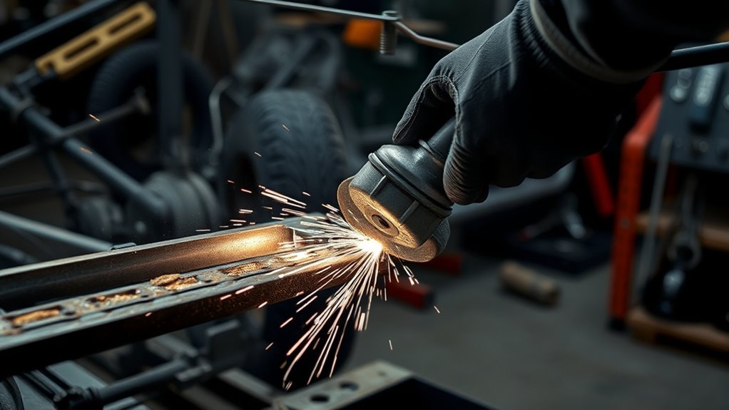
Mark the vehicle centerline, crossmember centerline, datum points, bolt holes, cut limits, and reference dimensions before removing any seam or flange. Photograph and record the original measurements so you can identify movement during fitment and welding.
Remove only the seam, flange, pinch-weld lip, coating, or rail material identified by the installation drawing. Do not strip away “every trace” of a factory flange unless the instructions specifically call for full removal. Factory seams may contribute to stiffness or join more than one layer of metal.
Make controlled cuts and inspect the rail as each layer becomes visible. Look for:
- Deep pitting or scale
- Cracks extending from holes or previous welds
- Separated factory seams
- Stretched, buckled, or kinked metal
- Overlapping repairs or filler hiding damage
- Thin edges that cannot support the specified weld
If any of these conditions appear, stop and determine the approved rail repair or replacement procedure before continuing. Do not bridge rust holes or thin metal with a larger bead.
Clean the approved weld zone to sound metal. Remove paint, seam sealer, undercoating, oil, moisture, rust, scale, zinc coating, and grinding residue far enough from the joint to prevent contamination, while preserving coatings outside the required work zone. See the site’s guide to cleaning mild steel for welding for general surface-preparation methods.
Pro Tip: Use layout dye or a paint marker to label centerlines, no-cut zones, bolt-hole centers, and measurement points. Re-mark them after grinding so the references remain visible throughout the installation.
Mock Up the Suspension Crossmember
Place the suspension crossmember into the chassis and compare its position with the supplied drawings. Install any temporary fixtures, spacers, locating plates, engine-mount references, control-arm pivots, spring pocket covers, or alignment bars included with the kit.
Bring the assembly into position without using the bolts or clamps to force a large gap closed. A forced fit stores stress in the parts and may pull the rail, spring pockets, or control-arm mounts out of position when the clamps are released.
Check the following measurements on both sides:
- Crossmember centerline to vehicle centerline
- Forward and rear reference-point spacing
- Diagonal measurements between opposite mounting points
- Height from the specified datum plane
- Spring pocket and control-arm pivot spacing
- Clearance for the engine, oil pan, steering, exhaust, brakes, wheels, and suspension travel
Do not substitute a tape-measure body edge for a specified structural datum point. If the vehicle maker provides exact dimensions, use those values and the appropriate tram gauge or three-dimensional measuring system. I-CAR notes that modern vehicles may require exact measurements rather than a generic tolerance. Review its repair-tolerance guidance before accepting the fit.
Once the crossmember rests against the prepared surfaces without bind, install the temporary or permanent bolts stated by the manufacturer. Tighten only in the sequence and to the stage required for mock-up.
Trim the Pinch Weld Lip and Seams
Use a grinder, saw, drill, or cutoff wheel suitable for the specified material to trim only the marked pinch-weld lip and seam areas. Keep sparks away from lines, wiring, glass, batteries, fuel vapors, interior materials, and hidden cavities. The site’s angle-grinder fire-prevention guide covers common spark hazards.
Make several small cuts rather than removing a large section at once. Deburr each edge and test-fit the crossmember after every adjustment. The goal is the joint gap and contact condition shown in the installation instructions, not simply the tightest fit you can create.
Do not fill an excessive gap by increasing weld size, adding scrap as an unapproved backing strip, or pulling the rails together with bolts. Correct the fit or obtain an approved repair method.
If the rail or component is zinc-coated, remove the coating from the stated weld zone and control the fume exposure. The site’s guides to welding galvanized steel and removing zinc coating provide supplemental preparation information. They do not replace the vehicle or kit procedure.
Note: Stop if cleaning exposes heavy rust, a crack, a separated reinforcement, previous collision damage, or steel that is thinner than the approved joint can accept. Repair or replace the damaged base structure before installing the crossmember.
Align the Spring Pocket Cover Mounts
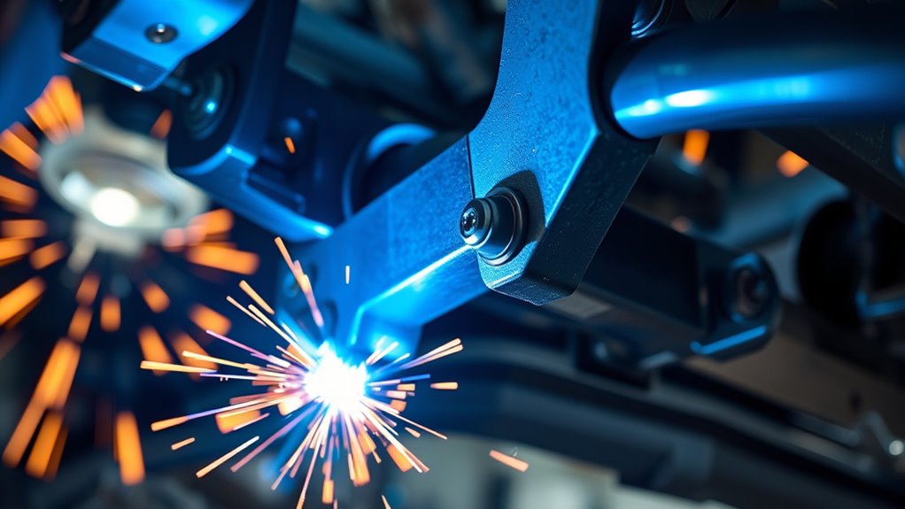
Fit the spring pocket cover mounts in the position and orientation shown by the supplied diagrams. Confirm that right- and left-side parts have not been swapped and that every formed edge, flange, hole, spacer, and reinforcement faces the correct direction.
Check the specified spring pocket spacing, height, angle, and relationship to the crossmember, frame, control-arm mounts, steering, and surrounding sheet metal. A mount can appear level while still being displaced forward, rearward, inward, or outward.
Align Pocket Mounts
Bring each mount against the prepared surface without rocking or twisting. Use the manufacturer’s locating bolts, sleeves, spacers, fixture holes, or temporary brackets whenever they are supplied.
Remove only enough approved flange material to obtain the specified interface. Do not reshape a mount with uncontrolled heat or hammer a rail into position to hide a dimensional error.
Hold the parts with clamps that provide firm contact without distorting the flange. Position clamps away from required weld zones and verify that they will not block the torch or gun.
Verify Mount Placement
Measure both sides from the same structural reference points. Check diagonals as well as side-to-side dimensions because equal individual measurements do not always prove that the assembly is square.
Inspect each interface for:
- The specified joint gap
- Full contact where the drawing requires it
- No folded or trapped metal
- No interference with bolts, springs, control arms, steering, brakes, or wheels
- Clear access to every required weld
Record the measurements before tacking. Those values become the baseline for detecting weld movement.
Secure Before Welding
Install the specified bolts and tighten them in the stated sequence. Some fasteners may be temporary locating hardware, while others may remain as structural fasteners. Do not substitute an unknown bolt grade, change a sleeve, omit a washer, or reuse a torque-to-yield fastener unless the procedure permits it.
| Check | Action | Pass Condition |
|---|---|---|
| Drawings | Compare orientation and dimensions on both sides | All stated dimensions and directions match |
| Fasteners | Install the specified bolts, sleeves, and washers | Parts remain located without forced preload |
| Clearance | Check nearby suspension, steering, engine, brake, and wheel paths | No contact through the required operating range |
| Joint Fit | Inspect contact, gap, edge condition, and access | Joint matches the installation drawing |
| Final Measurement | Recheck width, height, centerline, and diagonals | Recorded values remain within the stated specification |
Do not begin welding until every pass condition is met.
Bolt the Crossmember Assembly in Place
Install the crossmember and spring pocket components with the exact fasteners required by the kit or vehicle manufacturer. A generic “high-strength bolt” description is not enough. Diameter, thread pitch, grade, coating, washer type, sleeve length, installation direction, lubrication condition, and torque method can all affect clamp load.
The bolts and clamps should hold an already-correct assembly in position. They should not be used to pull a misaligned crossmember or damaged frame rail into shape.
Snug the fasteners in the specified pattern while monitoring the centerline and diagonal measurements. If tightening a fastener moves the assembly, stop and correct the joint fit.
Some suspension fasteners receive final torque only at normal ride height to avoid preloading rubber bushings. Others must be torqued before welding. Follow the exact instruction for each fastener and record the final torque after the work is complete.
Verify Fitment Before Final Welds
Complete a full dimensional and clearance check before the first tack. Verify the crossmember location against the drawings, the vehicle centerline, the required datum plane, and every suspension mounting point.
Confirm that:
- The assembly is supported in the correct loaded or unloaded condition.
- The rails and crossmember are not twisted or pulled together by excessive clamp force.
- Each seam and flange has the specified joint fit.
- All required weld areas are accessible and clean.
- No line, wire, hose, module, glass, coating, sealer, foam, trim, or interior material remains exposed to heat or sparks.
- Temporary fixtures can remain in position for the required welding stage.
- Final measurements have been written down.
Place the welding work clamp on clean metal as close to the weld zone as practical and on the same structural component whenever possible. Do not allow welding current to find a path through bearings, steering parts, wiring, modules, hinges, or suspension joints.
Warning: Do not weld near fuel or brake lines, refrigerant lines, batteries, wiring, electronic modules, insulation, seam sealer, foam, undercoating, carpeting, or interior trim unless the procedure permits them to remain and they are protected by an approved method. Inspect the hidden side of the panel before, during, and after welding.
Choose the Approved Welding Process and Consumables
Do not choose TIG simply because it produces a neat bead, and do not choose MIG simply because it is faster. Use the process named in the crossmember and vehicle instructions. Depending on the material and design, the approved method may involve GMAW/MIG, GTAW/TIG, resistance spot welding, MIG brazing, plug welds, fillet welds, a mixed attachment method, or no field welding.
Confirm these details before setting up the machine:
- Base-metal type and thickness
- Welding process and polarity
- Filler classification and diameter
- Shielding gas and flow range
- Joint preparation and permitted gap
- Weld type, size, length, pitch, and location
- Required preheat, interpass limit, or prohibition on added heat
- Tack size and permitted tack locations
- Welding sequence and cooling requirements
- Required test coupons and acceptance method
Make practice welds on clean scrap of the same type and thickness whenever the procedure requires qualification or a setup check. Cut, bend, peel, or inspect the coupons by the stated method before welding the vehicle. I-CAR’s weld-inspection guidance recommends practice welds and inspection throughout the repair process.
Do not increase a weld’s size because it “looks stronger.” An oversized weld can add heat, distortion and stress without improving the joint. Follow the drawing rather than selecting a size from plate thickness alone. The site’s guide to fillet-weld sizing is supplemental general information, not a substitute for the specified structural weld.
Products Worth Considering

Crafted with precision, our steel plates are laser-cut, offering unparalleled edge smoothness and dimensional accuracy compared to stamped and sheared parts.

Material: low carbon steel; Finish: Plain

♛【What You Get】: You will get 5pcs welding coupons, which is 100mm/3.9inch in length, 50mm/1.96inch in width. Sufficient quantities and commonly used size of welding coupons are enough for your daily welding requires.
Weld the Crossmember and Inspect It
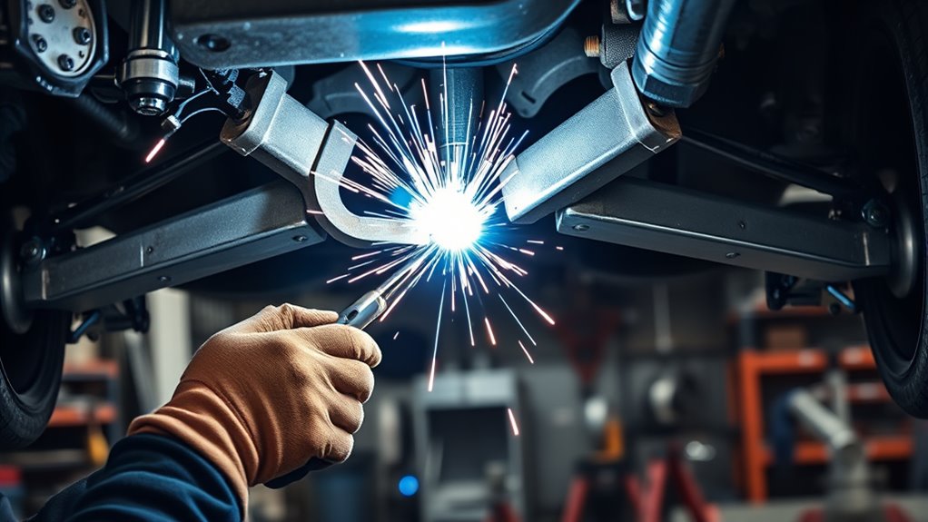
Place the specified tack welds in the stated order. Allow the assembly to return to a safe handling temperature, then recheck the centerline, height, width, diagonals, joint gaps, bolt fit and surrounding clearances. Correct tack-stage movement only by the method permitted in the instructions.
Apply the final welds using the approved machine settings, technique, sequence and weld dimensions. Alternate sides, skip locations, or pause between welds only when the procedure calls for that sequence. A generic distortion-control pattern can change the intended joint if it conflicts with the kit drawing.
Keep the work-clamp connection clean and close to the active weld area. Move it when needed so the welding-current path remains short. Do not quench structural welds with water or compressed air unless the procedure expressly requires a controlled cooling method.
If the manufacturer specifies TIG on an aluminum part, use the exact aluminum procedure and qualified filler. The site’s aluminum TIG guidance may help with general technique, but it cannot qualify a chassis repair or replace the component manufacturer’s instructions.
Inspect each weld as soon as it is accessible. Look for visible:
- Cracks
- Porosity
- Undercut
- Overlap or cold lap
- Incomplete weld length
- Incorrect bead size or location
- Arc strikes outside the permitted area
- Burn-through
- Contamination
- Heat distortion or movement
A surface inspection does not prove internal penetration or fusion. Complete the practice-coupon test, destructive test, dye-penetrant inspection, magnetic-particle inspection, ultrasonic inspection, or professional review required by the controlling procedure. Do not grind a structural weld smooth unless the instructions permit dressing and state the finished profile.
Warning: Do not apply suspension load or begin a road test to “see whether the weld holds.” Correct every defect, verify all dimensions, and obtain any required professional inspection before loading the repaired structure.
Restore Corrosion Protection
Allow the assembly to cool, then clean the repaired area without thinning the weld or base metal. Remove loose residue and inspect all exposed edges, seams, cavities and heat-affected surfaces.
Restore the coating system specified by the vehicle and component manufacturers. Depending on the location, this may include:
- Approved metal conditioner or primer
- Epoxy primer
- Seam sealer
- Topcoat or underbody coating
- Cavity wax inside rails and enclosed sections
- Stone-chip protection
- Replacement heat shields, plugs and grommets
Do not block factory drains, ventilation openings, locating holes or threaded mounting points. Apply cavity protection after welding and after any compatible primer or sealer has cured as directed. I-CAR’s corrosion-protection inspection guidance explains why removed seam sealer, cavity wax and related materials need to be restored.
Final Safety and Quality Checks
Before reinstalling the complete suspension, compare the finished dimensions with the original recorded values and the required specifications. Check the crossmember centerline, height, width, diagonals, spring pocket locations, control-arm pivots, steering-rack position and all related mounting points.
Complete a documented final inspection:
- All required welds are present in the correct locations and dimensions.
- No visible crack, porosity, undercut, burn-through, overlap or incomplete weld remains.
- The rail and crossmember show no unacceptable heat distortion.
- All temporary fixtures and locating hardware have been removed when required.
- Permanent bolts are correct and torqued using the specified procedure.
- Brake lines, fuel lines, wiring, grounds, hoses and modules are restored and secured.
- Coatings, seam sealer and cavity protection are complete.
- No drain, access hole, thread or mounting surface is blocked by coating or weld metal.
Reinstall the suspension, steering, brakes, drivetrain and related parts according to the service manual. Tighten suspension bushings at the required ride-height position when specified.
Cycle the steering and suspension by a safe workshop method before placing the vehicle on the road. Check for rubbing, binding, uneven movement and contact around the springs, shocks, control arms, steering linkage, brake hoses, wheels, tires, engine, oil pan and exhaust. Do not place hands between moving suspension parts.
Complete a professional wheel alignment. Confirm caster, camber, toe, steering-wheel position, ride height and thrust angle against the vehicle specification. If structural work, battery disconnection or part removal affects diagnostic or driver-assistance systems, complete all required pre-scan, post-scan, steering-angle reset, initialization or ADAS calibration.
A qualified technician should perform the first controlled road test only after every inspection and alignment requirement passes. Begin at low speed in a suitable area, listen for contact or movement, verify braking and steering, then recheck the repair and fasteners at the interval stated by the manufacturer.
Troubleshooting Crossmember Fitment and Welding
| Problem | Likely Cause | Safe Response |
|---|---|---|
| Crossmember will not sit flush | Unremoved interference, incorrect part orientation, distorted rail, or wrong kit | Stop forcing it, compare part numbers and drawings, find the interference, and measure the rail |
| Joint gap exceeds the drawing | Over-trimming, damaged rail, incorrect location, or distorted component | Do not bridge the gap with weld; obtain an approved refit or repair method |
| Measurements change after tacking | Insufficient fixturing, wrong sequence, poor fit, or excessive heat | Stop before final welding and correct the tack-stage movement by the approved procedure |
| Porosity appears | Contamination, moisture, coating, gas loss, wind, or incorrect setup | Stop, remove the defect as permitted, find the cause, clean the joint, and verify shielding and settings |
| Rail burns through or collapses | Thin rusted steel, excessive heat, wrong process, or unsupported gap | Stop welding and use the approved rail repair or replacement procedure |
| Suspension binds after assembly | Mount displacement, wrong spacers, preload, interference, or incorrect fastener torque | Do not drive; remeasure the mounting points and inspect every related component |
Products Worth Considering

Caliber Compass Patriot 4WD Rear Suspension Repair Kits: Rear Suspension Crossmember, Lower & Upper Control Arms, Lateral Links, Stabilizer Sway Bar End Link, Mounting Bolts

This Subframe Crossmember Bushings are OE design, Built to strict Quality control standards. Direct and easy replacement

Complete Kit: This subframe bushing kit includes 4 front subframe bushings for a complete repair solution.
Frequently Asked Questions
Can you weld a broken crossmember?
Not by default. A damaged original crossmember or subframe may require complete replacement, and welding or heat repair may be prohibited for its material or design. Weld it only when the vehicle maker provides an approved repair procedure for that exact component and damage location.
Can you weld a subframe on a car?
Only when the vehicle-specific repair information permits it. Many bolt-in subframes are replaced rather than welded. Material grade, crack location, corrosion, heat sensitivity, joint access, and suspension alignment all affect whether a repair is allowed.
Is MIG or TIG better for a suspension crossmember?
Neither process is universally better. Use the process specified by the vehicle or crossmember manufacturer. The correct choice depends on the base metal, thickness, joint design, weld location, heat limits, filler, equipment, and qualified procedure.
What is the best welder for car frame repair?
The best welder is one that can perform the exact approved process and settings for the repair and that the operator is qualified to use. GMAW or MIG is common in collision repair, but that does not make it suitable for every frame, rail, subframe, or aftermarket crossmember.
How much does it cost to get a chassis or crossmember welded?
There is no reliable universal price. The estimate depends on the vehicle, kit, corrosion or collision damage, disassembly, fabrication, welding procedure, inspection, coatings, suspension alignment, scanning, calibration, and local labor. A shop should inspect the vehicle and provide a written scope before quoting the work.
Should you bolt the crossmember before welding?
Yes, when the installation instructions use bolts, sleeves, or fixtures to locate the assembly. The hardware should hold a correctly fitted crossmember in position, not pull a twisted or misaligned assembly into place. Follow the stated tightening and final-torque sequence.
What should you inspect after welding a suspension crossmember?
Inspect weld location and size, visible cracks, porosity, undercut, overlap, incomplete welds, burn-through, arc strikes, heat distortion, chassis dimensions, bolt torque, suspension clearance, wiring and line protection, and restored corrosion coatings. Complete any additional test required by the approved procedure.
Do you need a wheel alignment after crossmember welding?
Yes. Welding or relocating suspension mounting points can affect caster, camber, toe, thrust angle, ride height, and steering-wheel position. Complete a professional alignment and any required steering-angle reset, scan, initialization, or ADAS calibration before normal driving.
Can you drive the vehicle after a visual weld inspection?
A visual check alone is not enough. The repair must meet the stated dimensions, weld requirements, torque values, corrosion-protection steps, suspension-clearance checks, alignment specifications, and any professional or nondestructive inspection required by the procedure.
Conclusion
A correctly installed suspension crossmember starts with an approved procedure, not a preferred welding process. Confirm the material and dimensions, support the chassis as directed, protect the vehicle, fit the assembly without preload, and use only the specified process, filler, weld size, and sequence. After welding, verify the structure, complete the required inspection, restore corrosion protection, align the suspension, and finish all required scans or calibrations. Do not return the vehicle to normal road use until every structural and suspension check passes.
Sources
- Ford Motor Company Structural Repairs Position Statement — supports the need to follow vehicle-maker structural repair procedures and specifications.
- I-CAR: Repair Tolerances — supports exact vehicle measurement and alignment requirements.
- I-CAR: Vehicle Protection When Welding — supports battery, electronics, interior, coating, and combustible-material protection.
- I-CAR: Weld Inspection During the Repair Process — supports practice welds, defect inspection, and following OEM procedures.
- OSHA: Controlling Hazardous Fume and Gases During Welding — supports material identification, coating removal, ventilation, and fume controls.
- OSHA 29 CFR 1910.252 — supports hot-work fire prevention, combustible control, and fire-watch precautions.



