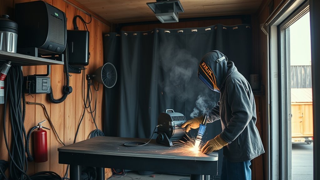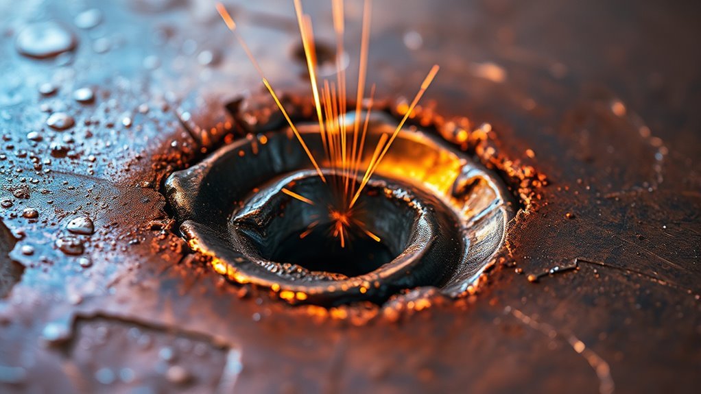
A weld crater is the depression left where a weld bead ends. A small, properly filled termination may be acceptable under the governing welding procedure, but a deep or cracked crater can reduce the weld’s effective size and create a weak point. Good crater control depends on the welding process, material, joint design, machine settings, and approved welding procedure.
Quick Answer
A weld crater forms when the arc stops before the shrinking weld pool receives enough filler metal. Prevent it by keeping the puddle controlled, filling the weld termination, and using a short backstep, downslope, crater timer, or other procedure-approved finish instead of snapping the arc away.
Key Takeaways
- A crater is a depression at a weld termination; a crater crack is a fracture that forms in or from that depression.
- Abrupt arc termination, an oversized puddle, insufficient filler, and poor machine sequencing raise the risk.
- MIG, flux-core, TIG, and stick welding require different crater-filling techniques.
- Do not lower current or change wire feed outside the approved WPS simply to make the crater smaller.
- A visible crack should be fully evaluated and repaired under the applicable code, WPS, and inspection requirements.
- Clean materials, suitable PPE, ventilation, and repeatable practice are essential parts of crater control.
At a Glance
| Time Required | About 5–15 minutes to diagnose and practice a correction; repair time varies with excavation and inspection requirements. |
| Difficulty | Beginner to intermediate for practice coupons; qualified personnel are required for code or safety-critical repairs. |
| Tools Needed | Welding machine, approved filler, PPE, cleaning tools, inspection light, WPS or procedure instructions, and repair tools when permitted. |
| Cost | Basic technique correction normally uses existing equipment; repair cost depends on consumables, excavation, rework, and inspection. |
What’s in This Article
- Understanding Weld Craters and Crater Cracks
- How Weld Craters Affect Weld Integrity
- How Weld Craters Form
- Common Causes of Weld Crater Formation
- Techniques for Filling Weld Craters
- How to Distinguish Craters From Other Defects
- How to Inspect a Weld Crater
- How to Repair a Weld Crater
- Troubleshooting Common Crater Problems
- Training Welders to Reduce Crater Issues
- Best Practices for Preventing Weld Craters
- Frequently Asked Questions
- Conclusion
- Sources
Understanding Weld Craters and Crater Cracks
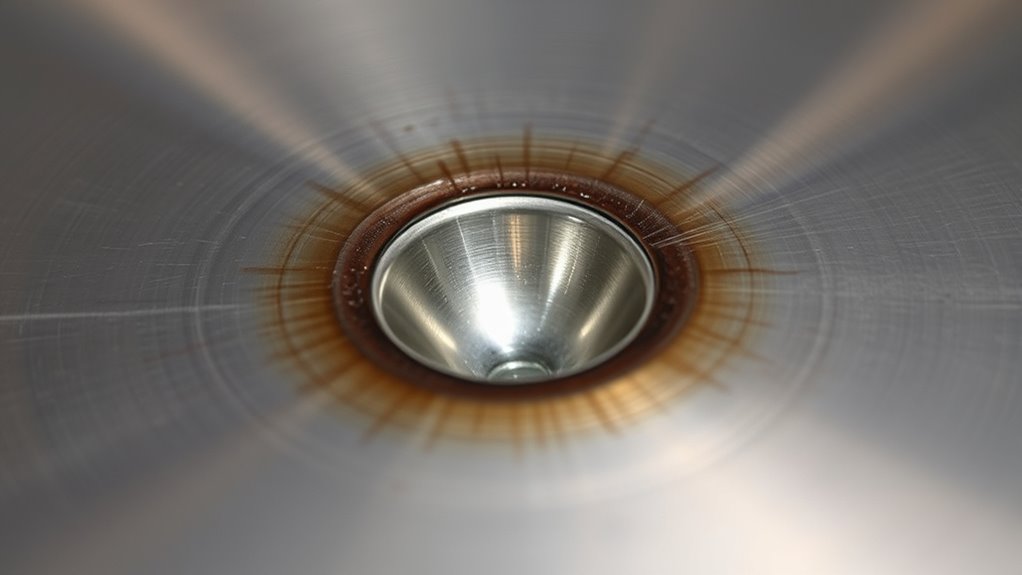
A weld crater is a shallow or deep depression at the point where the welding arc stops. It forms when the molten weld pool loses volume as it cools and solidifies without enough weld metal at the termination.
A crater crack is not the same thing as the crater itself. It is a hot crack that forms inside the crater or grows outward from it. The American Welding Society explains that crater cracks are commonly associated with improper arc termination and may become the starting point for a longer weld crack.
Not every visible dip is automatically a crack or an unacceptable defect. Acceptance depends on the applicable drawing, weld size, code, specification, and welding procedure. A crater that reduces the required weld throat or leg size may still be unacceptable even when no crack is visible.
A crater is not automatically a crack, but a poorly filled termination can become the starting point for a much larger weld failure.
You will see crater problems more often when the weld pool is large, the arc ends abruptly, filler addition stops too soon, or the machine’s end sequence is not set correctly. Position also matters because gravity can pull liquid metal away from the termination in vertical or overhead welding.
Good crater fill allows the bead to transition into the base metal without an abrupt notch. Learning how heat input and travel speed affect weld profile can help, but all parameter changes must stay within the approved welding procedure.
How Weld Craters Affect Weld Integrity
A deep crater can reduce weld integrity in two ways. First, it can leave the end of the weld smaller than the required size. Second, its concave shape can concentrate stress in a small area.
During cooling, the weld metal contracts. If the crater cannot carry the resulting strain, a hot crack may form before the weld has fully solidified. The crack can remain confined to the crater or extend lengthwise through the weld.
Crater-related defects deserve extra attention when the part will experience:
- Repeated or cyclic loading
- Vibration
- Bending or impact
- Thermal cycling
- High joint restraint
- Pressure, lifting, structural, or vehicle-safety loads
Warning: Do not leave a visible crater crack in a structural, pressure-retaining, lifting, rollover-protection, suspension, steering, or other safety-critical weld. Stop work and follow the applicable repair procedure, welding code, and inspection requirements.
Do not respond to crater problems by automatically lowering amperage or voltage. Excessive heat can create an oversized puddle, but insufficient heat can cause lack of fusion or an undersized weld. Use the approved heat input, travel speed, wire feed, and crater sequence specified by the WPS or qualified procedure. Guidance on controlling heat while stick welding stainless steel may be useful for that specific process and material, but it does not replace the job’s WPS.
How Do Weld Craters Form During the Welding Process?
A crater forms during the last moments of a weld. When the arc stops, the remaining liquid metal begins to lose heat. The outer edges of the pool often solidify first while the hotter center continues to contract.
If enough filler metal remains in the pool and the heat tapers in a controlled way, the weld end can freeze with a full or slightly crowned profile. If filler stops too early or power is removed instantly, the center can sink and leave an underfilled termination.
Puddle size, travel angle, arc length, electrode extension, joint restraint, material chemistry, filler selection, and welding position all influence the final shape. Maintaining proper electrode extension when flux-core welding supports arc stability, but it is only one part of crater control.
Factors That Influence Crater Formation
- Weld-pool size: A large liquid pool leaves more metal to contract at the end.
- Arc termination: Snapping the electrode or torch away removes heat and filler too quickly.
- Filler timing: Stopping wire or filler-rod addition before the pool is filled leaves lost volume uncompensated.
- Welding position: Gravity affects how the liquid metal settles in vertical and overhead welds.
- Joint restraint: A rigid joint cannot move freely as the weld contracts, which raises stress.
- Material and filler chemistry: Some alloy combinations are more sensitive to solidification cracking.
- Machine sequence: Final current, voltage, wire feed, downslope time, burnback, and post-flow settings can change the termination.
What Happens During Solidification?
Solidification begins at the cooler fusion boundary and moves toward the center of the puddle. As the final liquid metal freezes, it must withstand shrinkage strain from the surrounding weld and base metal.
A deep, concave termination has less metal across its center than a filled termination. That geometry can intensify local stress. Filling the crater before breaking the arc gives the termination a better cross-section and lowers the chance of a centerline or star-shaped crack.
Weld Crater Versus Crater Crack
| Condition | What It Means | Typical Action |
|---|---|---|
| Filled crater | The termination is filled to the required weld profile and has no visible crack. | Inspect against the drawing, WPS, and acceptance standard. |
| Underfilled crater | A depression reduces the termination’s cross-section but no crack is visible. | Evaluate weld size and acceptance limits; repair if required. |
| Crater crack | A fracture appears in or extends from the weld termination. | Stop and use the approved crack-removal, repair, and inspection process. |
Common Causes of Weld Crater Formation
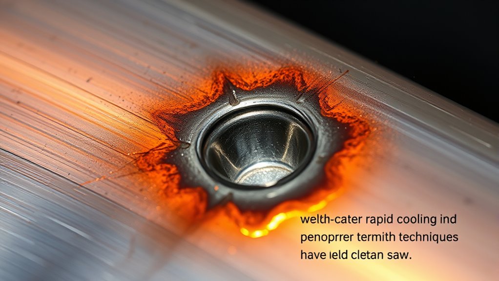
Most crater defects trace back to the relationship between puddle size, filler delivery, and arc termination. The problem is rarely solved by changing only one setting without checking the rest of the procedure.
Oversized or Poorly Controlled Weld Pool
High current, excessive voltage, slow travel, a long arc, or an incorrect torch angle can create a large or difficult-to-control puddle. When that puddle reaches the end of the weld, it may shrink into a deeper crater.
The correction is not always “turn the heat down.” Compare the actual settings with the WPS, machine chart, or qualified procedure. Also check travel speed, contact-tip-to-work distance, electrode extension, joint fit-up, and bead size.
Abrupt Arc Termination
Stopping the arc instantly is one of the most common causes of an underfilled weld end. With TIG, the problem often occurs when the operator removes filler rod and current at the same time. With MIG or flux-core, releasing the trigger may stop the arc and wire feed before the crater is filled.
A brief pause, approved trigger sequence, programmed crater cycle, downslope, or short return into the still-molten bead can produce a fuller termination.
Insufficient Filler Metal
The puddle loses volume as it solidifies. If filler addition stops too soon, the center may sink below the surrounding bead.
Use these habits:
- Keep filler addition steady as the weld approaches the stop.
- Use the machine’s crater sequence when the WPS permits it.
- For TIG, continue adding filler while tapering current.
- For wire processes, use the approved pause, backstep, or trigger method.
- Do not add an oversized lump that hides lack of fusion beneath the surface.
Material and Filler-Metal Effects
Aluminum transfers heat rapidly and has significant thermal expansion and solidification shrinkage. These properties make termination control especially important. Miller notes that unfilled aluminum MIG craters create stress points that can lead to cracking, while crater timers or a controlled trigger sequence can help fill the termination.
Filler-metal selection must match the base-alloy combination and service requirements. Do not choose 4043, 5356, or another aluminum filler only because it is commonly available. Follow the WPS, engineering specification, and a current manufacturer selection guide such as Lincoln Electric’s aluminum welding guidance.
Contamination and Shielding Problems
Dirt, oil, oxide, moisture, coating residue, and poor shielding gas do not usually create a crater by themselves, but they can add porosity, inclusions, unstable arc behavior, or cracking to an already weak termination.
Verify that the base metal and filler are clean, the gas flow is correct, the nozzle is clear, and drafts are not disturbing the shielding envelope.
Effective Techniques for Filling Weld Craters
The best crater-fill method depends on the welding process and the approved procedure. Practice the method on a coupon before using it on production work.
Products Worth Considering

Liquid Paste Filling Range: 5-50ml (Adjustable by scale). Food grade 304 stainless steel material ensures it can be used for all paste and liquids with good fluidity (no particulate matter). Such as shampoo, gel, body wash, essential oil, lip gloss, etc.

【Good Material】: Weld bead cleaning machine is composed of metal chassis, plastic and metal hardware, which makes it very strong, durable, stable performance and has a long service life.Weld cleaning machine has an internal fan for cooling, which can ensure that the machine can also run normally in the hot summer.
MIG, GMAW, and Flux-Core Welding
- Crater timer or end sequence: Use the machine’s programmed final-current, voltage, and wire-feed settings when they are included in the procedure.
- Brief pause: Hold the arc at the termination only long enough to fill the profile without overheating the joint.
- Short backstep: Reverse a short distance into the still-molten bead. The distance depends on bead size, position, and the WPS; it is not a fixed ½-inch rule.
- Approved trigger technique: On some manual MIG procedures, a quick second trigger action adds metal to the crater. Do not improvise this method on code work.
- Run-off tab: When the joint design and procedure allow it, continue the weld onto a removable tab so the crater forms outside the finished joint.
Correct polarity is essential for arc stability, but polarity alone will not fill the crater. Use the machine and consumable manufacturer’s data rather than treating a general flux-core and MIG settings chart as a substitute for the WPS.
TIG and GTAW
With TIG welding, continue feeding filler rod while gradually reducing current. Keep the torch over the puddle so shielding gas protects the hot termination until it solidifies.
Miller’s TIG crater-control guidance recommends continuing filler addition while reducing current or using the machine’s crater-control feature.
- Use foot-pedal control, a torch switch sequence, or programmed downslope as specified.
- Add small amounts of filler during the downslope instead of pulling the rod away immediately.
- Maintain shielding gas post-flow over the hot weld end.
- Avoid holding low current so long that the pool becomes contaminated or excessively wide.
Stick and SMAW
Do not snap the electrode away at the end of a stick weld. Shorten the arc, pause briefly, and make a small return movement into the bead if the procedure allows it.
Keep the electrode angle and arc length controlled during the finish. An amperage change may be appropriate for a different electrode or joint, but it should be based on the electrode manufacturer’s range and the WPS. A stick welding amperage chart is a starting reference, not an acceptance standard.
Aluminum Welding
Crater fill is especially important in aluminum welding. A crater-finish feature, downslope, controlled trigger sequence, or short backstep can reduce the depth of the termination. Miller’s MIG defect guide identifies unfilled aluminum craters as stress points that may lead to cracking.
Do not assume that a crater-control program is correct because it is enabled. Confirm final current, voltage, wire-feed speed, ramp time, burnback, and gas post-flow on test coupons before production.
When a Side Step Is Used
Some welders use a small sideways wash at the termination to move metal into the crater. This method can leave an uneven or off-center profile if the movement is too large. Use it only when it is part of approved training or the welding procedure. A controlled pause, downslope, short backstep, or run-off tab is usually easier to repeat.
Pro Tip: Practice five identical welds on clean coupons and compare only the final half-inch of each bead. A repeatable termination matters more than one unusually good-looking finish.
Good joint preparation and welding fundamentals give every crater-control technique a better chance to work. Clean fit-up, stable parameters, and consistent travel are more reliable than trying to repair the termination with a last-second motion.
How to Distinguish Weld Craters From Other Defects
A crater is normally located where a bead stops. Other defects may occur anywhere along the weld or may have a different shape and cause.
| Condition | Typical Appearance | Common Cause |
|---|---|---|
| Weld crater | A depression at the end of the bead | Underfilled arc termination |
| Crater crack | A line, star, or center crack in the termination | Solidification stress and poor crater fill |
| Porosity | Rounded pinholes or cavities, sometimes spread through the bead | Trapped gas, contamination, or shielding loss |
| Undercut | A groove melted along a weld toe | Excessive heat, speed, arc length, or poor angle |
| Lack of fusion | An unfused interface that may not be visible at the surface | Insufficient energy, poor angle, fast travel, or contamination |
| Burn-through | A hole through the base metal | Excessive heat, slow travel, or a large root opening |
Understanding gas entrapment and welding porosity helps prevent a pore at the termination from being mistaken for a shrinkage crack. When the indication is unclear, stop and have it evaluated rather than covering it with more weld metal.
How to Inspect a Weld Crater
Inspect the termination after it has cooled enough to examine safely. Use suitable lighting and clean away slag, spatter, soot, or oxide that blocks the view.
- Locate every stop and restart. Crater problems are often concentrated at bead terminations and tie-ins.
- Check the profile. Look for a deep depression, concavity, pinhole, star-shaped line, or centerline indication.
- Check weld size. Confirm that the termination still meets the required leg, throat, reinforcement, or groove profile.
- Check the weld toes. Look for cracks or undercut extending away from the crater.
- Compare with the acceptance standard. Use the drawing, WPS, code, customer specification, or inspector’s criteria.
- Escalate suspected cracks. A qualified inspector may require liquid-penetrant, magnetic-particle, or another examination method suitable for the material and code.
Note: A smooth surface does not prove that the weld is sound below the surface. Do not use visual appearance alone when the procedure requires nondestructive examination.
How to Repair a Weld Crater
Repair depends on whether the termination is merely underfilled or contains a crack, pore, slag, or lack of fusion. Do not begin a production repair until the applicable procedure permits it.
- Stop and identify the governing requirements. Review the drawing, WPS, repair procedure, code, and inspection hold points.
- Mark the affected area. Include the entire visible indication and any area identified by inspection.
- Remove the defect to sound metal. Use the approved grinding, machining, or gouging method. A crack must be removed completely rather than covered with new weld metal.
- Verify removal when required. The inspector may call for visual, penetrant, magnetic-particle, or another examination after excavation.
- Clean the repair area. Remove abrasive residue, oil, oxide, slag, moisture, and contamination. Use dedicated tools where required for aluminum or stainless steel.
- Restore the joint profile. Reweld with the approved process, filler, preheat, interpass temperature, and crater-fill technique.
- Inspect the completed repair. Confirm weld size, profile, fusion, and freedom from cracks or other rejectable indications.
- Document the repair when required. Record the welder, WPS, location, inspection results, and any authorized deviation.
Warning: Do not weld over a visible crater crack. The added metal may hide the surface while leaving part of the crack underneath.
Products Worth Considering

【Designed For Automotive Repair Work】Spot weld panel chisel Designed for automotive body repair work, precisely removes auto body spot welds and easily separates metal panels. It is suitable for a wide range of bodywork, include accident repairs, vehicle dismantling, door and fender replacement, and the separation of welds on frames and chassis, ensuring efficient performance to meet your needs.

UL CERTIFIED: Our Plastic Welder, the factory, and the process have been tested, approved, and Certified by Underwriters Laboratories (UL). Safety is our number one priority

Troubleshooting Common Issues With Weld Craters
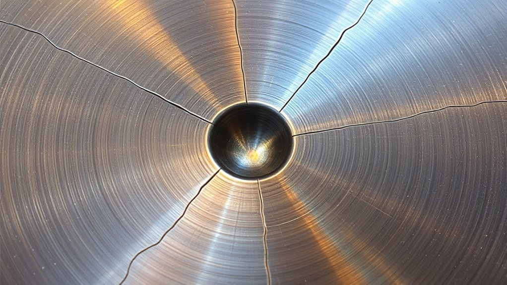
Start by examining the shape of the termination and noting whether the problem occurs on every weld, only in one position, or only after the machine warms up.
| What You See | Likely Causes | What to Check |
|---|---|---|
| Deep crater with no visible crack | Abrupt stop, insufficient filler, oversized puddle, short crater time | Termination motion, crater timer, final wire feed, travel speed, WPS settings |
| Star or centerline crack | Underfilled crater, crack-sensitive alloy, restraint, incorrect filler | Full crack removal, filler compatibility, joint restraint, procedure qualification |
| Pinhole at the center | Shielding loss, contamination, excessive gas turbulence, torch removed too soon | Gas flow, leaks, drafts, nozzle condition, cleaning, post-flow |
| Large raised button at the stop | Excessive pause, too much filler, overly high crater wire feed | Crater duration, filler timing, final current, bead-size requirement |
| Crater appears mainly in vertical or overhead welding | Gravity, excessive puddle size, poor angle, slow freeze control | Position-qualified WPS, travel angle, puddle size, electrode classification |
| Crater settings cause burnback or wire sticking | Incorrect final wire feed, voltage, burnback, or timing | Machine manual, contact tip, liner, crater sequence, wire-feed calibration |
Surface condition also matters. Remove dirt, oil, moisture, paint, and coating according to the approved procedure. When welding galvanized steel, do not rely on casual coating removal as the only safety control. Grinding can create zinc-bearing dust, and residual coating can produce hazardous fumes.
OSHA’s general welding requirements include ventilation provisions for zinc-bearing metals and coatings. Use suitable local exhaust, respiratory protection when required, safe coating-removal methods, and proper housekeeping. Additional process information is available in this guide to MIG welding galvanized steel.
Tips for Training Welders to Reduce Crater Issues
Training should make the weld termination a separate skill rather than treating it as the final instant of the bead.
- Explain the difference between a crater and a crater crack. Use cleaned examples that show an acceptable termination, an underfilled crater, and a cracked crater.
- Practice one process at a time. TIG downslope, MIG crater timing, flux-core termination, and stick backstep require different hand movements.
- Use identical coupons. Keep material, joint, position, filler, and settings the same while changing only the termination method.
- Record machine settings. Note current, voltage, wire feed, travel speed, crater time, final current, burnback, and gas post-flow where applicable.
- Clean and inspect every stop. Review crater depth, crack indications, weld size, porosity, and toe profile.
- Repeat until the result is consistent. One acceptable bead does not prove a repeatable technique.
- Introduce code acceptance criteria. Teach welders to distinguish appearance preferences from actual drawing, WPS, and code requirements.
Machine practice should use the same controls welders will encounter in production. When crater-fill settings are available, train welders to understand what the settings change rather than simply copying a number.
Best Practices for Preventing Weld Craters
Reliable crater prevention starts before the arc is struck and continues through final inspection.
- Follow the WPS: Use the approved process, filler, polarity, current, voltage, wire feed, travel range, and preheat requirements.
- Control puddle size: Avoid an oversized or unstable pool, but do not reduce heat below what is needed for fusion.
- Keep filler available through the finish: Do not stop filler delivery before the termination is filled.
- Use machine controls correctly: Verify crater time, downslope, final current, final wire feed, burnback, and post-flow on a coupon.
- Use a short, controlled finish: Pause, backstep, overlap, or use a trigger sequence only as the procedure permits.
- Use tabs where practical: Run-on and run-off tabs can move the termination away from the finished joint.
- Place stops carefully: When the procedure allows a choice, avoid ending directly in a highly stressed location.
- Clean base and filler metals: Remove contamination with tools and methods suitable for the alloy.
- Select compatible filler: Base the choice on the alloy combination, service conditions, and engineering requirements.
- Inspect every termination: Check the final profile, weld size, and freedom from cracks.
Maintaining appropriate weld sizing also prevents unnecessary puddle volume and heat. The required weld size must come from the design or procedure rather than appearance alone.
Frequently Asked Questions
What causes craters in welding?
A weld crater forms when the weld pool contracts at the end of a bead without enough filler metal to maintain the required profile. Abrupt arc termination, an oversized puddle, insufficient filler, poor travel control, and incorrect crater settings can make the depression deeper.
Can a weld crater cause cracking?
Yes. An underfilled crater has a reduced cross-section and can concentrate solidification stress. A crack may form inside the crater and, in some cases, continue lengthwise through the weld.
How do you prevent crater cracks in welding?
Fill the termination before breaking the arc. Depending on the process, use gradual current reduction, continued filler addition, a programmed crater cycle, a short backstep, an approved trigger sequence, or a run-off tab. Keep all changes within the WPS and machine instructions.
Should you grind out a weld crater before repair?
An uncracked, underfilled crater may only need the repair allowed by the governing procedure. A cracked crater must be excavated completely to sound metal with an approved method. Inspection may be required after removal and again after rewelding.
Are weld craters the same as porosity?
No. A crater is the weld-end depression left by arc termination. Porosity consists of gas cavities or pinholes caused by contamination, moisture, shielding problems, or gas entrapment. A pore can appear inside a crater, but the two conditions have different causes.
Is every weld crater unacceptable?
Not necessarily. Acceptance depends on weld size, profile, crack indications, the drawing, the WPS, and the governing code or customer specification. A visible crack should be treated as unacceptable until evaluated under those requirements.
What is a crater-fill setting on a welder?
A crater-fill setting controls part of the weld-ending sequence. Depending on the machine, it may taper current, voltage, or wire-feed speed for a set time. The correct values depend on the process, material, joint, filler, and qualified welding procedure.
Why are crater cracks common in aluminum welding?
Aluminum’s thermal expansion, heat transfer, and solidification behavior can create substantial shrinkage strain at an underfilled termination. Proper filler selection, crater control, joint design, and procedure qualification are especially important.
Safety Disclaimer: This article is for general information and does not replace a welding procedure specification, welding code, equipment manual, engineering instruction, workplace hazard assessment, or guidance from a qualified welding professional or inspector. Use suitable eye, face, hand, body, respiratory, ventilation, and fire protection. Do not perform an unapproved repair on a structural, pressure-retaining, lifting, vehicle-safety, or other critical component.
Conclusion
Weld craters matter because the end of a bead must carry the same required load as the rest of the weld. A deep termination can reduce weld size, and a crater crack can grow beyond the small area visible at the surface.
Prevent problems by following the WPS, controlling puddle size, keeping filler available through the finish, and using the correct termination method for MIG, flux-core, TIG, stick, or aluminum welding. Inspect every stop, and never cover a suspected crack without fully evaluating and removing it under an approved repair procedure.
Sources
- American Welding Society — What Is Weld Cracking? — crater-crack formation, propagation, prevention, and repair context.
- Miller — Common TIG Welding Problems — TIG downslope, continued filler addition, cleaning, and crater-control guidance.
- Miller — Common MIG Weld Defects on Aluminum and Steel — aluminum craters, stress concentration, and crater-timer use.
- Lincoln Electric — A Guide to Aluminum Welding — aluminum welding characteristics, consumables, and crack-prevention considerations.
- OSHA 29 CFR 1910.252 — General Welding Requirements — ventilation, zinc-bearing materials, cleaning compounds, PPE, and workplace safety controls.