Automotive welding can restore a rusted panel, fabricate a bracket, repair an exhaust part, or replace a collision-damaged body component. The process uses controlled heat, pressure, or both to join metal. The difficult part is not simply making a bead—it is choosing a repair method that preserves the vehicle’s strength, electronics, corrosion protection, and original crash performance.
Quick Answer
MIG or MAG welding is practical for many mild-steel automotive repairs, TIG gives precise control for clean fabrication work, and resistance spot welding joins accessible overlapping panels. For collision repairs, however, the vehicle maker’s procedure—not a general rule—must specify the approved joint, process, wire, gas, weld locations, and testing.
Key Takeaways
- MIG or MAG welding is common for mild-steel panels and fabrication, but it is not approved for every structural vehicle component.
- Identify the vehicle, repair location, metal grade, joint design, wire, gas, and approved attachment method before welding.
- High-strength and ultra-high-strength steels can lose important properties when heated outside the vehicle maker’s limits.
- Hybrid and electric vehicles may require low-voltage disconnection, high-voltage de-energization, component removal, and trained personnel.
- Make and destructively test matching weld coupons before welding a collision-repair joint when the OEM procedure or shop process requires it.
- After welding, inspect the joint, correct defects properly, and restore every required layer of corrosion protection.
At a Glance
| Time Required | From less than an hour for simple bench fabrication to several days for removal, structural replacement, refinishing, scanning, and reassembly |
| Difficulty | Moderate for basic mild-steel fabrication; advanced and safety-critical for structural, aluminum, UHSS, hybrid, or EV repairs |
| Tools Needed | Approved welder and consumables, helmet, gloves, flame-resistant clothing, extraction equipment, clamps, grinder, measuring tools, test coupons, and fire-control equipment |
| Cost | Varies widely with access, material, replacement parts, corrosion, required equipment, refinishing, calibration, and labor |
| Controlling Rule | Use the vehicle-specific body repair procedure for every collision-related attachment, sectioning, or structural weld |
What Is Automotive Welding?
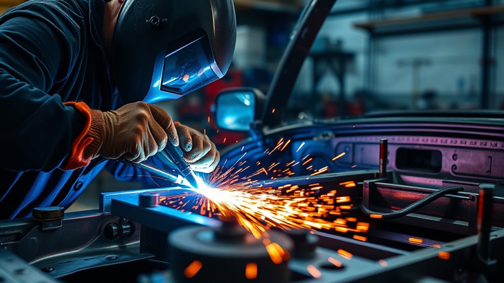
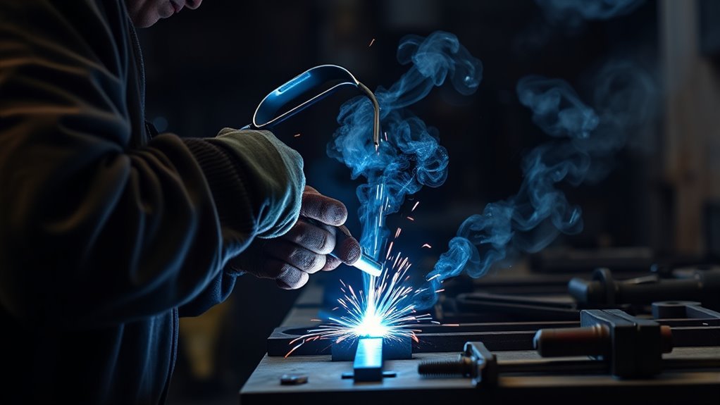
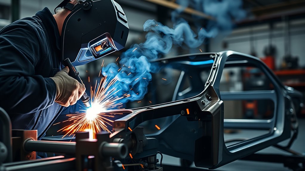
Automotive welding is the process of joining vehicle metal components with heat, pressure, or both. Depending on the process, the base metal may melt and fuse with filler wire, or resistance and clamping pressure may create a weld nugget between overlapping sheets.
The term covers several different types of work. A welder may fabricate an exhaust bracket on a bench, replace a cosmetic outer panel, repair rust in mild sheet steel, build a race-car component, or install a collision-replacement structural part. These jobs do not carry the same risks or use the same procedures.
For general fabrication, you select a process by material, thickness, access, joint design, and finish requirements. For collision repair, you must also protect crashworthiness, occupant-restraint mounting points, corrosion resistance, sensors, wiring, and high-voltage systems. The repair method must therefore come from current service information for the exact vehicle.
Filler selection also matters. The wire or rod must be compatible with the base metal and strong enough for the joint. This is especially important when working with high-strength steel or stainless components; background guidance on stainless-steel filler and shielding choices can help with general fabrication, but it does not replace an OEM collision-repair specification.
Warning: Do not improvise repairs to a frame rail, crumple zone, roof rail, pillar reinforcement, suspension mount, seatbelt anchor, airbag mounting area, high-voltage battery enclosure, fuel tank, pressurized container, or safety-critical wheel. Use the current vehicle-maker procedure and qualified personnel. Some damaged parts must be replaced rather than heated, straightened, sectioned, or welded.
A weld that looks smooth can still be the wrong repair. On a modern vehicle, the approved material, location, attachment method, heat input, and test result matter as much as appearance.
Verify the Vehicle, Material, and Repair Procedure First
Before choosing MIG, TIG, spot welding, brazing, adhesive, or mechanical fasteners, identify the exact vehicle and damaged component. Record the VIN, model year, body style, powertrain, and relevant options. Then obtain the current body repair manual, welding guidelines, position statements, and component-replacement procedure.
This step matters because a panel that looks like ordinary steel may contain several grades of high-strength steel, reinforcements, coatings, adhesives, and tailored thicknesses. The approved method can also change between model years or between two locations on the same panel.
- Identify the part: Confirm whether it is cosmetic, load bearing, part of a crash-energy path, or connected to an occupant-restraint mounting point.
- Identify the material: Check the OEM material map or repair manual for mild steel, high-strength steel, ultra-high-strength steel, aluminum, stainless steel, cast material, or a mixed-material assembly.
- Check repairability: Determine whether straightening, sectioning, partial replacement, heating, or welding is allowed.
- Confirm the attachment method: The procedure may call for MAG plug welds, butt welds, squeeze-type resistance spot welds, MIG brazing, adhesive, rivets, bolts, or a combination.
- Confirm consumables: Use the required wire classification, diameter, shielding gas, electrode tips, primer, adhesive, and corrosion-protection products.
- Confirm weld details: Follow specified hole diameter, weld count, weld spacing, joint overlap, flange preparation, location, and sequence.
- Confirm testing: Make matching test coupons and perform the required destructive test before welding the vehicle.
Current I-CAR welding and MIG-brazing resources show why collision repair now includes multiple attachment technologies rather than one universal welding process. Acura’s September 2025 welding and sectioning guidelines also demonstrate that approved methods change with steel strength and repair location.
Note: “MIG” is commonly used as a general shop term, but some OEM information distinguishes inert-gas MIG welding or brazing from active-gas MAG welding. Use the terminology, gas mixture, and process specified by the vehicle maker.
How Automotive Welding Works
Automotive welding works by creating a controlled joint between prepared pieces of metal. Arc processes form an electrical arc between an electrode and the work. Resistance spot welding passes current through clamped overlapping sheets. Each process must deliver enough energy for fusion without creating unacceptable distortion, burn-through, contamination, or heat damage.
Welding Preparation Steps
Start in a clean, dry, fire-resistant work area. Wear a properly selected welding helmet, safety glasses, gloves, hearing protection, and flame-resistant clothing. Position source-capture ventilation close enough to remove fumes without pulling shielding gas away from the weld.
- Read the complete repair procedure before cutting or removing the damaged part.
- Inspect both sides of the work area for fuel lines, brake lines, wiring, electronic modules, carpet, foam, sound deadening, seam sealer, undercoating, and closed cavities.
- Follow the specified battery-disconnection, power-down, and system-isolation steps.
- Remove paint, rust, grease, oxide, adhesive, coating, and contamination only as far as the procedure requires.
- Prepare the flange, overlap, root gap, plug-weld hole, bevel, or backing arrangement exactly as specified.
- Clamp the panels in final alignment and verify measurements before welding.
- Install the correct wire, gas, polarity, torch parts, spot-welder tips, and other consumables.
- Make test welds on coupons that match the vehicle joint’s material, thickness, layer count, coating, and orientation.
- Destructively test the coupons and adjust the equipment until the weld meets the required result.
- Place a suitable extinguisher nearby and assign a fire watch when sparks or heat can reach hidden areas.
Detailed surface preparation for galvanized steel can reduce contamination, but coated automotive panels also require fume control and restoration of corrosion protection after the weld.
Joining Methods Explained
The correct joining method depends on the vehicle and the component. Common methods include:
- GMAW/MIG or MAG welding: A continuously fed wire acts as the electrode and filler. It is practical for many mild-steel repairs and fabrication jobs, but wire strength, gas, transfer mode, and joint design must match the procedure.
- GTAW/TIG welding: A non-consumable tungsten electrode creates the arc. The operator adds filler separately when needed. TIG offers fine control for clean fabrication, aluminum, stainless steel, tubing, and visible work, but it is not automatically approved for structural body repair.
- Squeeze-type resistance spot welding: Copper-alloy electrodes clamp accessible overlapping sheets and pass current through them. The process can reproduce factory-style spot attachments when the equipment, tips, force, current, time, and test result meet the OEM requirement.
- GMA plug welding: A weld is made through a prepared hole in one panel to join it to the panel beneath. Hole size, number, spacing, penetration, and location must follow the procedure.
- MIG brazing: A lower-melting filler such as silicon bronze joins specified coated-steel flanges with less base-metal melting than fusion welding. It is used only where approved.
- Adhesive and mechanical fastening: Modern repairs may combine structural adhesive with welds, rivets, bolts, or other fasteners. Adhesive is not an unapproved substitute for a weld, and a weld is not an automatic substitute for adhesive.
High-strength and ultra-high-strength steels need special care because uncontrolled heat can alter their properties. Acura’s current guidance, for example, limits some butt-welding and plug-welding operations according to steel strength and the model-specific body manual. That is why a general thickness chart cannot determine structural-repair approval.
Post-Weld Inspection Process
Inspect each joint after it has cooled as directed. Solid-wire MIG/MAG and TIG welds normally do not leave a slag layer, so clean spatter, soot, oxide, and residue without thinning the surrounding panel. Remove slag only when the selected process actually produces it.
- Compare the finished joint with the approved procedure, including weld count, location, spacing, length, and joint profile.
- Check for cracks, pinholes, porosity, undercut, overlap, excessive reinforcement, burn-through, incomplete fusion, missed welds, or panel distortion.
- Inspect the back side where access allows and confirm that surrounding wiring, coatings, trim, and components were not damaged.
- Perform any required peel, chisel, bend, nugget, or destructive coupon test.
- Use dye penetrant, magnetic-particle, ultrasonic, or another nondestructive method only when the procedure, engineering plan, or applicable inspection standard calls for it.
- If a weld is defective, stop. Remove or repair the defect as directed rather than covering it with another bead.
- Repeat the coupon test after changing settings, consumables, panel stack, or electrode condition.
I-CAR advises following OEM welding requirements and using destructive testing to help confirm a complete and safe repair. Its spot-welder setup guidance reinforces that machine settings and test results must be verified rather than assumed.
Essential Automotive Welding Tools and Safety Gear
Automotive welding requires more than a power source and torch. The exact equipment depends on the approved process, material, joint, and vehicle.
- An approved MIG/MAG, TIG, pulse, aluminum, or squeeze-type resistance spot welder
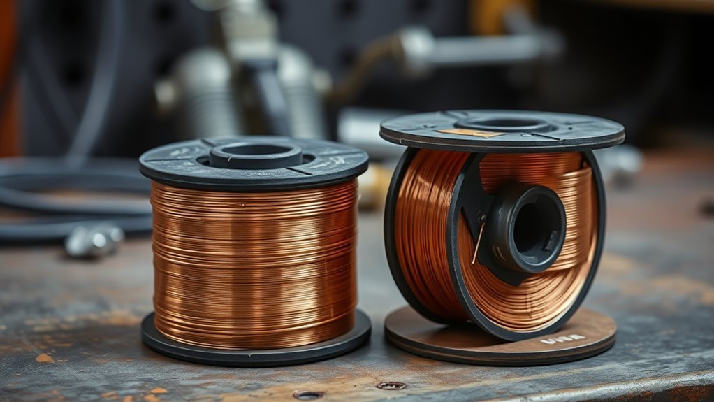
- Correct wire, filler rod, shielding gas, drive rolls, liner, contact tips, nozzles, and electrode caps
- Welding helmet with a suitable filter shade and safety glasses underneath
- Flame-resistant jacket, trousers, gloves, closed footwear, and hearing protection
- Local exhaust or source-capture fume extraction
- A hazard-appropriate respirator when required by the exposure assessment and respiratory-protection program
- Clamps, panel-holding tools, measuring equipment, and vehicle fixtures
- Angle grinder, files, wire brushes, abrasives, spot-weld cutters, and approved cutting tools
- Weld-test coupons and tools for peel, bend, chisel, or nugget testing
- Fire extinguisher, welding blanket, spark shields, and fire-watch equipment
- Epoxy primer, approved weld-through primer where specified, seam sealer, cavity wax, and other corrosion-protection materials
An autodarkening welding helmet, gloves, and flame-resistant clothing protect against arc radiation, hot metal, and sparks. This guide to protective clothing for arc welding explains the basic clothing categories, while workplace requirements should follow the applicable safety program and equipment instructions.
OSHA’s welding, cutting, and brazing standards address fire prevention, ventilation, PPE, and related hazards. NIOSH also warns that welding-fume composition changes with the base metal, coatings, consumables, and process.
Note: Galvanized, stainless, painted, plated, undercoated, or contaminated metal can create hazardous fumes and gases. Use source capture, remove coatings as the procedure allows, keep your breathing zone out of the plume, and use respiratory protection selected for the actual hazard. A fan that merely blows fumes across the shop is not a substitute for proper control.
Products Worth Considering

Sateen Fabric: The IRONCAT 7050 FR Sateen cotton jacket features 9 oz. sateen fabric with black anodized snaps on the front for secure fastening
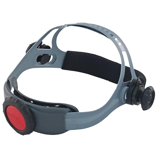
REPLACEMENT WELDING HELMET HEADGEAR - Jackson Safety's Premium 370 Speed Dial Replacement Headgear offers a perfect fit and secure hold for your welding hood

Hybrid and Electric Vehicle Welding Safety
Do not treat a hybrid or electric vehicle like a conventional vehicle with an extra battery. High-voltage cables, battery packs, capacitors, inverters, onboard chargers, electric air-conditioning compressors, and other components can create electrical, fire, and chemical hazards.
Before welding:
- Obtain the exact OEM welding and high-voltage disable procedure.
- Confirm that the technician performing the power-down is trained and authorized for that vehicle.
- Disconnect the low-voltage system when required.
- De-energize the high-voltage system using the specified service disconnect and waiting period.
- Verify the system state with the procedure’s approved test method and PPE when required.
- Remove or protect nearby electronic and high-voltage components when the maker specifies a distance or removal requirement.
- Do not weld near a damaged, leaking, overheated, or compromised battery pack.
- Follow the prescribed reactivation, diagnostic scanning, fault-clearing, and calibration steps after repair.
Volvo’s published EV welding position states that the 12 V battery must be disconnected and the high-voltage system de-energized before welding. It also requires nearby electronic units or the high-voltage battery to be removed in certain circumstances. See the Volvo EV welding position summarized by I-CAR.
Warning: Pulling a service disconnect does not automatically prove that every high-voltage component is safe to touch. Follow the complete OEM shutdown, waiting, verification, PPE, and restart procedure. Do not work on a damaged battery enclosure unless the vehicle maker provides a procedure and the facility is equipped for high-voltage battery hazards.
MIG Welding for Car Repairs
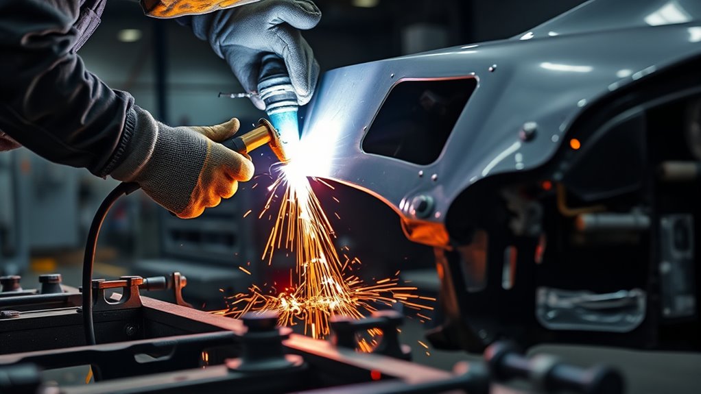
MIG or MAG welding is a practical choice for many automotive fabrication and mild-steel repair jobs because the process feeds wire continuously and is comparatively easy to start. It can make tack welds, short stitch welds, butt welds, lap welds, and plug welds when the material and repair plan allow them.
The machine, wire, shielding gas, polarity, contact-tip size, torch angle, travel speed, and voltage or amperage relationship must all suit the joint. Aluminum also needs compatible equipment, wire feeding, gas, and cleaning practices; changing only the spool of wire is not enough.
- Use the OEM specification or equipment chart as the starting point.
- Install the specified wire classification and diameter.
- Confirm gas type and flow, polarity, liner, drive-roll tension, contact-tip condition, and ground connection.
- Prepare matching coupons with the same material, thickness, layer count, coating, gap, and orientation.
- Adjust the machine until the test weld has the required profile and destructive-test result.
- Use controlled tacks or stitch sequences on thin cosmetic panels to limit heat buildup.
- Move around a large panel when practical instead of concentrating heat in one area.
- Allow cooling intervals that follow the repair plan; do not quench hot automotive steel unless the procedure expressly permits it.
Understanding the relationship between voltage, wire-feed speed, travel speed, arc length, and stick-out is more useful than relying on a single “amperage” number. These beginner welding setup principles can help with practice, but vehicle work should begin only after successful coupons.
Pro Tip: On thin cosmetic sheet metal, make a series of small, spaced welds and let the panel shed heat between them. Keep checking alignment with a straightedge. This reduces distortion, but it does not authorize stitch welding on a structural part when the OEM requires another attachment method.
Products Worth Considering

5 IN 1 MULTIFUNCTIONAL: Enjoy the convenience of a 5-in-1 welding machine that masterfully handles Gasless Flux Core MIG/Gas MIG/Spool Gun MIG/Stick/Lift TIG (additional lift TIG torch/spool gun required: B07YP9TQV1/B0B12JLSS9). This unit suits a wide range of welding applications and meets your various welding needs.
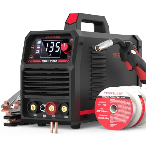
READY OUT OF THE BOX: Start welding immediately! It masterfully handles Gasless Flux Core MIG, Stick, and Lift TIG (Extra Lift TIG torch required). This budget-friendly 3-in-1 machine includes extra E71T-GS .030''&.035'' flux core wires, known for its smooth arc and high feedability. Say goodbye to heavy shielding gas cylinders—perfect for outdoor, windy, or all-position welding.

TIG and Spot Welding for Auto Body Work
TIG and resistance spot welding serve different purposes. TIG provides manual control over the arc and filler addition, while a squeeze-type resistance spot welder creates a weld nugget by clamping overlapping sheets and passing current through them.
TIG Welding Precision
TIG welding uses a non-consumable tungsten electrode and a shielding gas, commonly argon, to create a clean, controllable arc. It is useful for stainless exhaust components, aluminum fabrication, brackets, tubing, trim pieces, and custom work where finish and heat control matter.
TIG is not automatically the lowest-heat process. A slow travel speed, wide bead, poor fit-up, or repeated reheating can place substantial heat into a thin panel. Practice on matching scrap and control arc length, torch angle, filler addition, and travel speed.
- Remove grease, oxide, paint, plating, and contamination with material-appropriate tools.
- Use dedicated stainless or aluminum cleaning tools where cross-contamination is a concern.
- Choose the correct tungsten, cup, gas, polarity, current type, and filler rod.
- Keep a short, stable arc and add filler without touching the tungsten.
- Stop and regrind or replace contaminated tungsten.
- Use a test joint to verify penetration, profile, distortion, and strength.
Machine controls differ, so a brand-specific guide such as these Miller TIG settings for stainless steel should be treated as equipment background rather than a universal vehicle repair specification.
Spot Welding Uses
Squeeze-type resistance spot welding is often used on accessible overlapping steel flanges. The electrode tips clamp the panel stack, apply force, and pass current through the sheets for a controlled time. Resistance at the interface creates a fused nugget.
A successful spot weld depends on more than placing the arms over the flange. Panel coatings, total stack thickness, tip shape, tip condition, shunting, clamp force, current, weld time, machine capability, access, and calibration all affect the result.
- Confirm that STRSW is approved at the repair location.
- Use the required electrode tips and dress or replace them as needed.
- Prepare the mating surfaces and apply weld-through primer only when the OEM procedure specifies it.
- Enter the required manual settings when automatic mode is not approved.
- Make and destructively test a matching coupon before welding the vehicle.
- Maintain the specified edge distance, weld spacing, and weld count.
- Retest after tip maintenance, equipment changes, or a change in panel stack.
Choosing the Right Method
Choose the method by working through the repair information rather than ranking processes as universally stronger or better.
- MIG/MAG: Practical for approved steel fusion welds, plug welds, and general fabrication.
- TIG: Precise for clean fabrication, specialty alloys, tubing, exhaust work, and visible joints when permitted.
- STRSW: Preferred for many factory-style overlapping panel attachments when both sides are accessible and the procedure approves it.
- MIG brazing: Used on specified coated-steel joints where lower heat input and the approved filler are required.
- Adhesive plus fasteners: Common on mixed-material or OEM-designed joints that use bonding with rivets, welds, or bolts.
- Replacement rather than welding: Required when the component, material, heat damage, crack, corrosion, or OEM instruction rules out repair.
Do not substitute TIG for MIG, plug welds for spot welds, welds for rivets, or extra welds for adhesive unless the vehicle maker provides that option. More weld metal can add heat and stiffness in the wrong place rather than improve the repair.
How to Prepare Metal for Welding
Good preparation improves fusion, reduces contamination, controls distortion, and helps the joint match its intended dimensions. Start by removing rust, paint, grease, seam sealer, adhesive, oxide, undercoating, or plating from the weld zone as required.
Do not strip a much larger area than necessary. Excessive coating removal creates additional refinishing work and exposes more metal to corrosion. On a collision repair, preserve factory e-coat outside the required heat-affected and bonding areas whenever the procedure allows it.
- Cut away metal that is too thin, cracked, heavily pitted, or outside the repairable limit.
- Use an approved cutting method that does not damage hidden reinforcements or neighboring panels.
- Dress the edge without reducing the remaining metal below specification.
- Prepare the required flange, overlap, bevel, plug-weld hole, or butt-joint gap.
- Trial-fit the replacement part and verify body measurements, gaps, and alignment.
- Clamp the assembly securely without forcing it into a stressed position.
- Clean the final weld area with a residue-free product suitable for the material.
- Keep stainless and aluminum preparation tools separate from carbon-steel tools when contamination matters.
For thin material, the principles in this guide to maintaining a clean surface when welding thin metal remain useful. However, self-shielded flux-core welding is generally a poor choice for many thin automotive body panels because it can produce more spatter, fumes, cleanup, and heat than an appropriate gas-shielded setup.
If plasma cutting is part of a fabrication job, confirm the machine’s rated capability instead of assuming it will make a clean precision cut at its maximum advertised thickness. This overview of plasma-cutter thickness capability explains the difference between quality cuts and maximum severance. Keep the cutting arc, heat, and sparks away from vehicle electronics, pressurized components, fuel systems, and high-voltage parts.
Common Automotive Welding Positions
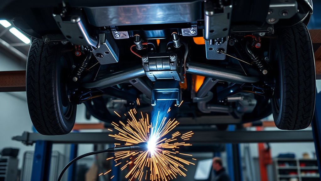
The welding position changes puddle control, visibility, travel speed, heat input, and the risk of molten metal falling onto the operator or vehicle. Use the process-specific work and travel angles recommended for the joint, wire, position, and machine.
- Flat: Usually the easiest position because gravity helps keep the puddle in the joint. Do not rely on a single fixed torch angle for every butt, lap, or T-joint.
- Horizontal: The puddle can sag toward the lower edge. Adjust technique and settings according to the approved welding procedure and coupon result.
- Vertical: Travel direction and parameters depend on the process, transfer mode, material, and joint. Use matching vertical coupons before welding the vehicle.
- Overhead: Reduce puddle size and maintain full protective clothing. Shield glass, wiring, hoses, trim, and underbody materials from falling sparks and metal.
A “push” or “pull” direction is not a universal rule for thin or thick material. Direction affects visibility, gas coverage, bead shape, and penetration, but the correct choice depends on the process and procedure. Flux-containing processes also behave differently, as covered in these flux-core welding tips.
Fire, Fume, and Hidden-Damage Control
Vehicle fires often begin out of sight. Sparks can travel through holes and seams into carpet, foam, seam sealer, wiring coverings, sound insulation, dry debris, or trim. Heat can also damage a component without creating an immediate flame.
- Inspect and clear both sides of the weld area.
- Remove nearby trim, carpet, foam, modules, hoses, fuel lines, and other vulnerable parts when required.
- Use welding blankets and noncombustible spark shields without trapping heat against the vehicle.
- Keep an appropriate, inspected extinguisher within reach.
- Assign another person as a fire watch when the welder cannot see the back side or adjacent cavity.
- Reinspect the work area and hidden spaces during and after the job.
- Follow the shop’s hot-work permit and fire-watch duration where applicable.
OSHA’s general welding requirements address fire prevention, removal or shielding of combustibles, and ventilation. See 29 CFR 1910.252. A broader plasma cutting and hot-work safety checklist can also help identify common spark, PPE, and workspace hazards.
Manual vs. Robotic Welding
Manual and robotic welding both have automotive applications, but they solve different problems. Manual welding is suited to one-off fabrication, varied damage, limited production, and work that requires continuous judgment. Robotic welding is suited to controlled, repeatable production with consistent parts and validated fixtures.
Manual Welding Benefits
A skilled technician can adjust torch position, access, sequence, and travel in response to an irregular repair. Manual welding also avoids the programming and fixture cost of an automated cell.
- Practical for one-off parts and low-volume fabrication
- Adaptable to repairs with changing access or geometry
- Suitable for MIG/MAG, TIG, brazing, and approved manual spot-welder settings
- Allows direct inspection between welds
- Requires strong training, procedure discipline, and repeatable coupon testing
Portable combination equipment, including a plasma cutter and welder combination machine, may save space in a fabrication shop. It does not replace a vehicle-maker-required pulse welder, aluminum system, resistance spot welder, fume-control system, or dedicated collision-repair tooling.
Robotic Welding Advantages
Robotic welding can improve cycle-time consistency and repeatability when the parts, fixtures, program, consumables, and incoming quality remain controlled. It can also move the operator farther from the arc during normal production.
- Repeatable torch path and travel speed
- Consistent timing and programmed parameters
- High output on validated, repetitive parts
- Data collection for process monitoring
- Less direct arc exposure during automatic operation
Automation does not remove the need for guarding, fume extraction, maintenance, inspection, tip changes, fixture checks, programming control, destructive testing, and trained personnel.
Automation Transition Steps
- Document the current joint, cycle time, defects, consumables, and inspection method.
- Confirm that part volume and repeatability justify automation.
- Select the process, robot, power source, positioner, fixture, guarding, and extraction system.
- Program torch access, collision limits, start and stop locations, and parameter windows.
- Validate the cell with representative parts and destructive tests.
- Train operators to load parts, recognize faults, inspect welds, and respond safely.
- Set schedules for cleaning, calibration, tip replacement, wire delivery, fixture checks, and preventive maintenance.
- Control program changes and revalidate the process after significant changes.
Vision-Guided Robotic Welding
Some robotic cells use cameras, laser sensors, touch sensing, through-arc sensing, or other systems to locate a seam and correct a programmed path. Supported systems may also adapt selected parameters within validated limits.
These capabilities should not be described as universal automatic correction. A system may compensate for a limited position change but still fail when the gap, contamination, part stack, fit-up, reflectivity, joint design, or material falls outside its programmed range.
Successful vision-guided welding still requires stable fixtures, clean optics, sensor calibration, process limits, representative validation parts, inspection, and maintenance. The technology can reduce variation, but it does not make a poorly designed or contaminated joint acceptable.
Common Automotive Welding Mistakes
- Starting without the OEM procedure: The chosen weld may be prohibited for the material or location.
- Assuming every steel panel is mild steel: Modern bodies may combine several steel grades in one assembly.
- Welding over rust, paint, adhesive, or undercoating: Contamination can cause fumes, porosity, unstable arc behavior, and incomplete fusion.
- Using unapproved wire or gas: The joint may not achieve the required strength or corrosion performance.
- Skipping test coupons: A machine setting that worked yesterday may fail after changes in tips, voltage supply, gas, wire, panel stack, or coating.
- Using too much heat: Excess heat can distort thin panels and damage high-strength steel, coatings, electronics, adhesive, and nearby trim.
- Using too little heat: The bead may sit on the surface without adequate fusion.
- Ignoring fit-up: Wide or uneven gaps increase filler demand, heat input, and distortion.
- Adding extra welds “for strength”: Extra welds can increase heat and change the intended stiffness of a crash structure.
- Covering a defective weld: Another bead does not automatically remove porosity, cracks, or lack of fusion.
- Quenching the panel: Rapid cooling can create distortion or conflict with the material’s repair procedure.
- Skipping corrosion protection: Bare steel, damaged e-coat, open seams, and unprotected cavities can rust rapidly.
- Failing to inspect hidden areas: Heat may damage wiring, foam, trim, hoses, or coatings behind the weld.
Automotive Weld Defect Troubleshooting
Stop when a weld does not look or test correctly. Diagnose the cause before continuing on the vehicle.
- Porosity: Check for dirty metal, coating residue, drafts, blocked gas flow, leaks, excessive stick-out, contaminated wire, or an empty cylinder.
- Burn-through: Reduce heat input as the procedure permits, shorten weld duration, improve fit-up, use the approved backing method, and retest on matching coupons.
- Lack of fusion: Check voltage or amperage, wire-feed relationship, travel speed, work angle, joint preparation, ground connection, and contamination.
- Excessive spatter: Check polarity, gas, contact-tip condition, wire quality, surface contamination, voltage, wire-feed speed, and arc length.
- Undercut: Correct excessive heat, travel speed, torch angle, or arc length and retest.
- Distortion: Improve fit-up and clamping, reduce concentrated heat, change the sequence, use shorter weld intervals where approved, and allow controlled cooling.
- Weak spot-weld coupon: Check tip shape and condition, panel stack, coatings, shunting, clamping force, current, weld time, machine supply, and manual settings.
- Cracking: Stop immediately. Confirm base material, filler compatibility, contamination, joint restraint, heat input, and whether the component is repairable.
Do not grind away so much material that a weak weld merely looks smooth. Appearance is only one inspection point; joint dimensions, fusion, nugget size, penetration where applicable, and destructive-test performance are more important.
Post-Weld Cleanup and Inspection
Let the joint cool according to the approved process. Clean it enough to inspect the surface without thinning the base metal, cutting into the weld, or removing required reinforcement.
- Remove loose spatter, soot, residue, and slag if the chosen process produced slag.
- Verify weld count, length, spacing, position, and joint dimensions.
- Inspect for cracks, porosity, undercut, overlap, incomplete fusion, burn-through, and distortion.
- Inspect the back side and nearby components for heat or spark damage.
- Correct defective welds using the approved rework method.
- Dress the weld only to the extent permitted by the repair procedure.
- Clean the area and apply the specified epoxy primer, seam sealer, adhesive, cavity wax, underbody coating, paint, and other corrosion protection.
- Reinstall removed components and restore grounds, wiring, insulation, shields, and trim.
- Reconnect and reactivate electrical systems using the proper sequence.
- Perform required diagnostic scans, calibrations, inspections, measurements, leak checks, or road tests.
- Document the repair procedure, equipment, consumables, settings, test results, weld locations, and corrosion-protection steps.
Weld-through primer is not a universal coating for every welded flange. Some OEMs specify it for particular resistance spot welds but prohibit it for certain plug welds, butt welds, or MIG-brazed joints because it can affect weld quality. Follow the process-specific instruction and protect exposed metal after inspection.
Sources
- OSHA 29 CFR 1910.252: General Welding Requirements — fire prevention, ventilation, equipment, and welding safety requirements
- NIOSH: Welding Fumes and Manganese — welding-fume composition and occupational exposure concerns
- I-CAR Welding and MIG Brazing Hotspot — collision-repair welding, MIG brazing, STRSW, and training resources
- Acura Body Repair Manual Welding and Sectioning Guideline Revisions — approved methods, HSS wire, primer, shielding gas, and UHSS restrictions
- Volvo Position Statement: Electric Vehicle Welding — low-voltage, high-voltage, electronic-component, and battery precautions
- U.S. Bureau of Labor Statistics: Welders, Cutters, Solderers, and Brazers — national wage and employment context
Frequently Asked Questions
How much does welding work on a car cost?
There is no reliable flat price for automotive welding. A small bench-welded bracket may require little labor, while rust removal, structural replacement, aluminum work, difficult access, refinishing, corrosion protection, scanning, and calibration can make a repair much more expensive. A shop must inspect the damage and review the OEM procedure before giving a meaningful estimate.
Can a welder make $100,000 a year?
It is possible, but it is not typical of the occupation as a whole. Six-figure earnings are more likely with extensive overtime, travel, hazardous or remote work, specialized certifications, supervision, business ownership, or a highly paid industry. The U.S. Bureau of Labor Statistics reported a $51,000 median annual wage for welders, cutters, solderers, and brazers in May 2024.
Is MMA or stick welding stronger than MIG?
Neither process is automatically stronger. Joint design, base metal, filler classification, preparation, settings, penetration, defects, and welder skill determine the result. Stick welding is useful for many heavier outdoor jobs, while gas-shielded MIG or MAG welding is usually easier to control on thin automotive sheet metal. The vehicle maker must approve the process for collision-related structural work.
What type of welding is best for car body panels?
MIG or MAG welding is practical for many mild-steel cosmetic repairs, while squeeze-type resistance spot welding is often used for approved overlapping flanges. TIG can be useful for clean custom fabrication. On a collision repair, the best method is the one specified for that vehicle, panel, material, and joint.
Can you weld over rust on a car?
No. Rust, paint, grease, seam sealer, and undercoating can contaminate the weld and hide metal that is too thin to repair. Remove severe corrosion and cut back to sound metal. Clean the approved weld zone to the condition required by the procedure before fitting the replacement metal.
Should you disconnect a car battery before welding?
Follow the vehicle maker’s procedure. It may require a specific shutdown sequence, memory or access preparations, low-voltage disconnection, and protection or removal of electronic modules. Hybrid and electric vehicles may also require high-voltage de-energization, a waiting period, verification, special PPE, and removal of nearby components.
Can you weld a cracked car frame at home?
A frame or structural crack should not be treated as a general home-welding job. The component may be made from heat-sensitive high-strength steel, may not be repairable, and may affect suspension alignment and crash performance. Have the damage measured and use the current OEM procedure or a qualified structural collision-repair facility.
What shielding gas should you use for automotive MIG welding?
Use the gas specified for the wire, process, equipment, base metal, and repair procedure. Common mild-steel MAG mixtures contain argon and carbon dioxide, aluminum MIG commonly uses argon, and MIG brazing may require 100% argon. Do not substitute a gas mixture merely because it produces an acceptable-looking bead.
Is it safe to weld galvanized automotive steel?
Galvanized steel can be welded only with suitable preparation, fume controls, PPE, consumables, and an approved process. Heating zinc coatings can produce zinc oxide fume. Remove coating only as required, use source-capture ventilation, follow respiratory-protection requirements, and restore the specified corrosion protection afterward.
Conclusion
Automotive welding is not one universal technique. MIG or MAG, TIG, resistance spot welding, plug welding, MIG brazing, adhesive, and mechanical fasteners each have valid uses, but the correct choice depends on the vehicle, material, component, and repair procedure.
For safe, dependable work, identify the metal before applying heat, isolate electrical and high-voltage systems, prepare the joint carefully, use the specified consumables, validate settings on matching coupons, inspect every weld, and restore corrosion protection. Cosmetic fabrication can be a rewarding shop skill. Structural collision repair demands current OEM information, proper equipment, documented testing, and trained judgment.