
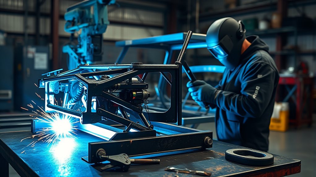
A vehicle structure is not just metal that needs to be joined. Its rails, pillars, crossmembers, reinforcements, crush zones, adhesives, and factory welds work together to manage loads and collision energy. That means the correct welding process is the one specified for the exact year, make, model, body style, material, and repair location—not simply the process a welder prefers.
Gas metal arc welding (GMAW), often called MIG or MAG welding, is common for approved steel repairs. However, a vehicle maker may instead require squeeze-type resistance spot welding (STRSW), MIG brazing, weld bonding, rivet bonding, full-part replacement, or a combination of methods. TIG is mainly relevant to custom tubular chassis work when the fabrication specification allows it, while stick welding is rarely appropriate for modern passenger-vehicle structures.
Quick Answer
There is no universal “best” process for every car frame. Follow the vehicle-specific repair procedure. GMAW/MIG is common for approved steel joints, but STRSW, MIG brazing, weld bonding, or rivet bonding may be required. Use TIG mainly for specified custom tubular chassis work, and avoid stick welding unless an approved procedure expressly permits it.
Key Takeaways
- Identify the vehicle by VIN, model year, body style, material, and exact repair location before choosing a joining method.
- GMAW/MIG is common for approved steel plug, stitch, and butt welds, but it is not automatically correct for every structural joint.
- Modern unibody structures may require STRSW, MIG brazing, structural adhesive, rivets, or complete part replacement.
- Do not preheat, section, reinforce, or substitute a weld process unless the OEM repair information allows it.
- Practice welds, destructive testing, vehicle protection, corrosion restoration, measurements, scans, and calibrations are part of a complete repair.
At a Glance
| Time Required | Varies by damage, measuring needs, part availability, OEM procedure, and required curing or calibration time |
| Difficulty | Expert; structural collision repair should be performed and inspected by trained professionals |
| Tools Needed | OEM repair information, measuring system, approved welder and consumables, clamps, extraction, PPE, fire protection, and inspection equipment |
| Cost | Requires a vehicle-specific professional estimate; process choice alone does not determine total repair cost |
What’s in This Article
- Start With OEM Repair Information
- Know Whether You Have a Frame or Unibody
- Compare the Main Joining Processes
- When MIG/MAG Is the Right Choice
- When TIG Welding Makes More Sense
- Why Stick Welding Usually Falls Short
- Match the Process to Material and Joint Design
- Use Other OEM Attachment Methods When Required
- Set Up the Vehicle and Welding Area
- Use the Approved Joint and Technique
- Handle Difficult Welding Positions Safely
- Inspect Welds and Restore Protection
- Fix Common Welding Problems
- Choose Equipment for the Procedure
- Check the Legal and Safety Side
- Frequently Asked Questions
- Sources
- Conclusion
Warning: A structurally incorrect weld can change how a vehicle carries loads or performs in another collision. Do not weld, section, straighten with heat, add reinforcement, or substitute an attachment method until the exact OEM procedure has been found and understood.
Start With OEM Repair Information, Not Welder Preference
The first step is to identify the vehicle by VIN, model year, body style, drivetrain, and exact damaged part. Two vehicles that look similar may use different steel grades, aluminum parts, adhesives, weld locations, or sectioning rules.
I-CAR states that vehicle-maker procedures are service specifications, not optional recommendations. Use the current body repair manual, collision repair manual, workshop manual, and OEM position statements for the exact vehicle. The procedure should tell you whether the part can be repaired, must be replaced, may be sectioned, and which joining method, wire, gas, adhesive, rivet, weld count, or test is required.
If no vehicle-specific procedure exists, do not invent one. Check the manufacturer’s general repair information and published position statements. A qualified collision repair facility may also need to contact the OEM technical information service or stop the repair until approved guidance is available.
The correct process is the process the vehicle maker specifies for that exact material, joint, and repair location.
Know Whether You Have a Full Frame, Unibody, or Tubular Chassis
Body-on-frame vehicles use separate frame rails and crossmembers that support the body. Unibody vehicles use the body shell, rails, pillars, floors, rockers, and reinforcements as one engineered structure. A custom tubular chassis is different again and may follow a drawing, welding procedure specification, sanctioning-body rulebook, or fabricator specification.
This distinction matters because the words “car frame” often get used for all three. A repair that is acceptable on a conventional mild-steel frame rail may be prohibited on a hot-stamped unibody reinforcement. A TIG-welded 4130 tube joint may be appropriate in a custom race chassis but not in a production passenger-vehicle pillar.
Note: Do not identify a structural material by appearance, spark pattern, magnet test, or thickness alone. Use the OEM body-construction diagram and repair information.
Compare the Main Joining Processes
| Process | Where It May Fit | Main Limitation |
| GMAW/MAG, commonly called MIG | Approved steel plug, stitch, seam, or butt welds; some approved aluminum work with dedicated equipment | Wire, gas, transfer mode, joint design, and settings must match the OEM procedure |
| STRSW | Replacing factory spot welds where electrode access and OEM requirements allow | Requires adequate clamp force, current, tip access, tip condition, and approved test results |
| MIG brazing | Specific heat-sensitive steel joints identified by the manufacturer | It is not a universal substitute for fusion welding and must be used only where specified |
| GTAW/TIG | Custom tubular chassis, specialty fabrication, and specific aluminum or steel work when the governing procedure permits it | Slow travel can add heat; it is rarely the specified process for production unibody structural replacement |
| SMAW/stick | Occasional heavy fabrication outside typical passenger-vehicle collision repair | Too much heat, slag, spatter, and limited control for many thin or coated automotive structures |
| Adhesive and rivet bonding | Steel, aluminum, or mixed-material joints specified by the OEM | Requires the exact products, fasteners, preparation, spacing, clamping, and cure conditions |
When MIG/MAG Is the Right Choice for Car Frame Repair
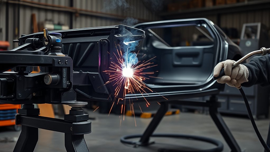
GMAW uses a continuously fed wire electrode and shielding gas. In North American shop language, it is often called MIG welding, even when an active-gas mix makes MAG the more precise term. For approved steel repairs, it can provide good control, repeatability, speed, and minimal slag.
That makes GMAW practical for many OEM-specified plug welds, stitch welds, and butt welds. It is also accessible for technicians learning wire-welder fundamentals. However, basic process familiarity is not enough for structural repair. The machine must be capable of the required transfer mode and output, and the wire, diameter, shielding gas, polarity, joint design, weld count, and settings must match the procedure.
Do not treat flux-cored wire as an automatic substitute for solid wire and gas. Flux-cored welding can be useful in general fabrication, and these flux-core welding tips explain the process, but a production vehicle structure should receive the attachment method and consumable specified by the vehicle maker.
Aluminum GMAW requires a suitable power source, wire-delivery system, correct filler alloy, dedicated tools, and contamination control. Some aluminum structures also use rivets and adhesive rather than a welded joint. The OEM procedure—not the fact that a machine can feed aluminum wire—decides whether welding is allowed.
Pro Tip: Before welding the vehicle, reproduce the joint on matching practice coupons and perform the test required by the OEM or training standard. A smooth-looking bead is not proof of adequate fusion or plug-weld nugget size.
When TIG Welding Makes More Sense
TIG welding gives the operator separate control over the arc and filler metal. It can produce precise, clean welds on properly prepared material, but it is not automatically a low-heat process. Slow travel, poor fit-up, or repeated passes can increase total heat input and enlarge the heat-affected zone.
TIG makes the most sense for custom tubular chassis, motorsport fabrication, specialty brackets, and certain aluminum or stainless work when the engineering drawing, welding procedure specification, sanctioning rules, or vehicle maker permits it. For 4130 chrome-moly tubing, filler choice, tube condition, joint fit, cleaning, sequence, and any heat-treatment requirement must come from the governing specification.
Do not substitute TIG for an OEM-specified STRSW, GMAW plug weld, MIG-brazed joint, weld-bonded flange, or rivet-bonded joint merely because TIG looks cleaner. Production structures are designed around specific attachment methods and heat input.
Shielding-gas control still matters. This guide to TIG settings for stainless steel is relevant only after the alloy and approved process have been confirmed; stainless settings should not be transferred to unknown frame material.
Why Stick Welding Usually Falls Short
Stick welding, or SMAW, is useful for many heavy-fabrication and field-repair jobs. It is usually a poor match for modern passenger-vehicle structures because thin or coated metal is easy to overheat, slag must be removed, and bead size can be difficult to control in tight flanges and complex joints.
Stick welding can also create more spatter and cleanup than the attachment methods normally used in collision repair. That increases the risk to glass, wiring, trim, seam sealer, foam, fuel-system parts, and nearby coatings.
The issue is not that stick welds can never be strong. The issue is that strength alone does not make an attachment method correct. A structural repair must reproduce the required joint, heat input, corrosion protection, and crash behavior. Unless an approved vehicle or fabrication procedure calls for SMAW, choose the specified process instead.
Keep extraction and airflow suitable for the material and coating. This hot-work PPE and ventilation checklist covers general shop precautions, while the vehicle repair procedure and workplace safety rules control the actual job.
Match the Process to Frame Material, Strength, Thickness, and Joint Design
Material thickness is only one input. You also need the material grade, coating, number of layers, joint access, attachment method, load path, and repair location.
Mild steel, HSS, and UHSS: High-strength and ultra-high-strength steels can be heat-sensitive. Some parts may be straightened cold, some may be replaced only at factory seams, and some may allow a specific sectioning joint. Honda/Acura’s welding and sectioning guidance, for example, limits certain weld types by steel strength and requires welding instructions to be followed exactly. Do not generalize one manufacturer’s limits to another vehicle.
Aluminum and mixed materials: Aluminum repair requires dedicated contamination control because embedded steel particles can contribute to corrosion. Mixed-material structures may use isolation materials, adhesives, and rivets to manage galvanic corrosion and heat. Follow the exact cleaning, fastener, adhesive, and joining procedure.
Custom tubular chassis: TIG or GMAW may be suitable when the design specification permits it. Tube alloy, wall thickness, joint geometry, filler metal, sequence, and inspection criteria should come from a qualified drawing or welding procedure—not a general car-body settings chart.
Stainless components: ER308L is commonly associated with 304-series stainless fabrication, but that does not make it suitable for an unknown structural part. Use 304 stainless welding guidance only when the part is positively identified as compatible stainless and the repair specification approves welding.
Note: A generic voltage-and-wire-speed chart is a starting point for practice coupons, not an OEM structural repair specification. Material stack-up, coatings, gap, transfer mode, wire, gas, and machine design can change the required settings.
Use Other OEM Attachment Methods When Required
Modern collision repair is not limited to MIG versus TIG. The I-CAR OEM Technical Information Matrix tracks manufacturer information on materials, sectioning, attachment methods, weld-through primer, corrosion protection, adhesives, and related repair requirements.
Squeeze-type resistance spot welding (STRSW) may be required to replace factory spot welds. The welder must provide the needed current and clamp force, the electrodes must reach the joint, and the tips must be correct and maintained. Practice welds and destructive tests help confirm the setup before welding the vehicle.
MIG brazing uses a lower-melting filler than fusion welding and may reduce heat to certain heat-sensitive joints. It should be used only where the vehicle maker specifies the joint, wire, gas, and technique.
Weld bonding combines an approved structural adhesive with spot welds or another specified weld. Rivet bonding combines approved rivets with adhesive. Do not change the adhesive, rivet type, hole size, spacing, flange preparation, open time, clamping method, or cure procedure.
Never add an unapproved backing plate, fish plate, gusset, sleeve, extra weld, or reinforcement “for safety.” Extra stiffness can move stress into a different area or alter how a crush zone responds.
Set Up the Vehicle and Car Frame Welding Gear
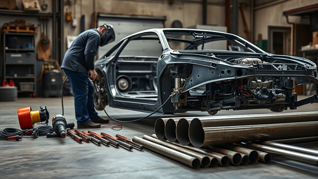
Once the repair method is confirmed, set up the vehicle, equipment, and work area in the order required by the OEM procedure and shop safety plan.
- Measure before cutting or welding. Confirm the vehicle is supported at the specified points and record structural dimensions. Correct pulling and alignment work must be completed in the proper sequence.
- Disable vehicle systems correctly. Follow the OEM waiting times and shutdown procedure for the 12-volt battery, restraint system, backup power supplies, and high-voltage system when applicable. Do not assume disconnecting one battery cable makes an EV or hybrid safe.
- Protect electronics. Keep the welding current path short, place the work clamp as close to the weld as the procedure allows, and keep cables away from modules, sensors, and wiring.
- Remove or shield fire hazards. Inspect both sides of the joint. Remove or protect trim, carpet, glass, wiring, fuel lines, brake lines, undercoating, seam sealer, foam, adhesive, and cavity wax within the required distance.
- Clean only the required area. Remove paint, corrosion, contamination, and coatings as directed. Do not grind away unnecessary metal or factory protection.
- Set up ventilation and PPE. Use a welding helmet with the proper shade, safety glasses, gloves, flame-resistant clothing, hearing protection as needed, and local exhaust that pulls fumes away from the breathing zone.
- Prepare the joint and clamps. Use the specified overlap, gap, plug-weld hole, flange, adhesive, and clamping method. Suitable clamps can hold parts in position, but they must not distort the assembly or block required access.
- Make and test practice welds. Use matching layer count, material, coating condition, wire, gas, and machine settings before touching the vehicle.
- Maintain a fire watch. Keep the correct extinguisher available, inspect hidden cavities during work, and recheck the vehicle after hot work is complete.
I-CAR’s vehicle-protection guidance calls for protecting nearby surfaces, removing combustible foams and sealers, shutting down electrical systems, and moving modules, batteries, sensors, and wiring away from the welding area as specified by the OEM.
OSHA’s welding-fume guidance also warns that outdoor or open-space welding does not guarantee adequate ventilation. Clean hazardous coatings as required, keep fumes out of the breathing zone, and use local exhaust or respiratory protection when the exposure assessment requires it.
Warning: Fuel vapors, batteries, pyrotechnic restraint devices, high-voltage components, hidden foam, seam sealer, and cavity wax can create fire, explosion, shock, or toxic-fume hazards. Follow the vehicle maker’s disable and removal procedures before hot work.
Products Worth Considering
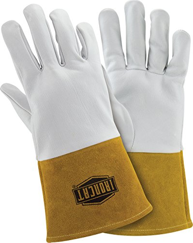
Work Safety Gear: TIG welding gloves protect hands during welding jobs. Commonly used by welding operators engaged in steel mills, manufacturing, automotive, glass welding, and torch work, these safety gloves protect from sparks and molten metal fragments

𝐏𝐫𝐨𝐟𝐞𝐬𝐬𝐢𝐨𝐧𝐚𝐥-𝐆𝐫𝐚𝐝𝐞 𝐋𝐞𝐧𝐬 𝐂𝐨𝐚𝐭𝐢𝐧𝐠: Compared to standard safety glasses, our premium coating delivers superior performance: impact-resistant, scratch-resistant, and acid/alkali-resistant on the outside, with an advanced anti-fog treatment on the inside to maintain clear vision in changing temperature and humidity conditions. Durable and easy to clean – simply rinse with water and wipe dry.

Size - 150 x 155 x 50mm / 6 x 6.1 x 2"(L*W*H); Weight: 44g, The protective glasses are lightweight, do not put pressure on the bridge of the nose, and are comfortable to wear.
Use the Approved Joint and Technique for Stronger Repairs
Joint preparation affects fit, penetration, weld size, corrosion protection, and distortion. Follow the exact flange width, root gap, overlap, plug-hole diameter, weld count, pitch, sequence, and finish specified for the repair.
Joint prep matters. Remove rust, oil, paint, sealers, and coatings only where the procedure calls for bare metal. Bevel an edge only when the approved joint design requires it. Keep panels aligned and clamped without forcing them into a stressed position. These general joint-preparation tips can help with practice work, but the OEM dimensions control the vehicle repair.
Control heat input. Do not “turn up the heat until it penetrates” or preheat a structural part unless the procedure says to do so. Heat can change the properties of HSS and UHSS. Use the specified machine mode, settings, wire, gas, stickout, travel speed, sequence, and cooling intervals. Stop if the panel distorts, coating burns far beyond the expected heat-affected zone, or the weld test fails.
Work angle and travel angle are different. A butt joint commonly uses a work angle near 90 degrees to the face of the joint, while a fillet joint often splits the included angle. Travel angle is the gun angle in the direction of motion. Miller’s automotive MIG guidance describes a normal travel-angle range of about 5 to 15 degrees, but the approved procedure and process setup still take priority.
Do not use a universal “push for thin, pull for thick” rule. Push or drag technique affects bead shape, visibility, penetration, and shielding differently depending on the process, transfer mode, material, position, and joint. Aluminum GMAW, for example, is normally pushed rather than dragged.
Do not reinforce a joint from an extra side unless the repair information calls for that reinforcement. The goal is to reproduce the specified structure, not create the largest possible weld.
Handle Flat, Vertical, and Overhead Positions Safely
Flat and horizontal welding positions are usually easier to control, but vehicle access may force a technician to work vertically or overhead. Do not change the joint, cut location, or attachment method merely to make access easier.
For approved GMAW joints, keep the work angle centered on the joint and use the travel angle, wire stickout, sequence, and settings that produced a passing practice weld. Do not automatically lower voltage and wire feed for every vertical or overhead joint; an untested change can create lack of fusion.
If a removable service part can be safely positioned for better access without violating the procedure, prepare and weld it as allowed. When the vehicle itself must be welded in position, protect the operator and vehicle from falling sparks and molten metal, maintain gas coverage, and inspect hidden surfaces for fire.
For thin exterior sheet metal that is not part of the structural frame decision, review these automotive sheet-metal welding practices. Structural rails, pillars, rockers, and reinforcements still require their own vehicle-specific procedures.
Inspect Welds, Dimensions, Electronics, and Corrosion Protection
A structural repair is not complete when the arc stops. Inspection should occur before, during, and after welding.
- Test before vehicle welding. Make practice welds and perform the required peel, chisel, bend, or destructive test on coupons.
- Inspect each stage. Check weld location, count, spacing, size, penetration, porosity, undercut, burn-through, cracks, contamination, incomplete fusion, and distortion before covering the joint.
- Confirm dimensions. Re-measure datum points, openings, suspension mounting areas, and related structural dimensions according to the repair plan.
- Restore corrosion protection. Apply the specified epoxy primer, seam sealer, adhesive, underbody coating, and cavity wax in the correct order. Weld-through primer is not suitable for every process or joint.
- Restore vehicle systems. Reconnect systems in the specified sequence and complete required diagnostic scans, steering-angle resets, restraint checks, ADAS calibrations, or other post-repair operations.
- Document the repair. Save the OEM procedure, weld-test results, measurements, products, lot information when required, scans, calibrations, and inspection records.
I-CAR recommends practice welds on matching scrap and inspection for porosity, penetration, cleanliness, and incomplete welds. The Honda/Acura guidance linked earlier also shows why corrosion products must match the process: it directs technicians not to use weld-through primer for certain MAG and MIG-brazed joints and calls for epoxy primer over completed exposed steel.
Fix Common Car Frame Welding Problems
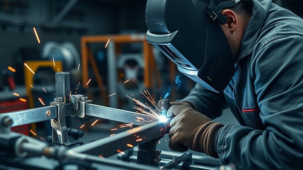
When a test weld or vehicle weld fails inspection, stop and correct the cause. Do not cover a defect with a larger bead.
| Problem | Likely Causes | Safe Correction |
| Lack of fusion or weak plug weld | Wrong settings, poor fit-up, incorrect hole size, coating in the joint, long stickout, poor ground, or wrong wire/gas | Return to matching coupons, correct the setup, retest destructively, and repair the vehicle joint only as the OEM procedure permits |
| Porosity | Contamination, drafts, gas leak, blocked nozzle, excessive stickout, moisture, paint, primer, oil, or rust | Remove the defective weld as allowed, clean correctly, restore gas coverage, check equipment, and retest |
| Burn-through or excessive heat-affected zone | Excess heat, slow travel, large gap, repeated passes, wrong transfer mode, or wrong joint design | Stop, reassess whether the part remains repairable, correct fit and settings on coupons, and follow OEM instructions for the damaged joint |
| Undercut, oversized bead, or excess buildup | Wrong angle, excessive heat, poor travel speed, excessive weaving, or incorrect wire feed | Correct technique and parameters on coupons; do not grind a structural weld below the permitted finished size |
| Panel movement or distortion | Poor clamping, incorrect sequence, forced fit, too much continuous welding, or inadequate cooling control | Stop before adding more heat, verify dimensions, and use the specified clamping and weld sequence |
| Unstable arc or heavy spatter | Incorrect polarity, poor ground, worn tip, wire-feed issue, wrong gas, contamination, or mismatched settings | Check the machine, consumables, polarity, gas, cable path, and coupon results before continuing |
A generic MIG wire-speed and voltage chart can help establish a practice starting point, but the passing coupon and OEM procedure determine whether the setup is acceptable.
Pro Tip: Photograph passing destructive tests, machine settings, joint preparation, measurements, and corrosion-protection steps. Good documentation supports quality control and makes final inspection easier.
Choose Welding Equipment for the Repair Procedure
Do not buy or select a welder based only on maximum amperage or input voltage. Start with the vehicles and procedures the shop must repair, then choose equipment that meets those requirements.
For steel GMAW, consider the required wire diameters, shielding gases, short-circuit or pulse capability, output range, duty cycle, stable low-end control, and access to approved programs or settings. A small 120-volt machine may be suitable for practice and light nonstructural work but may not meet the output, duty-cycle, or process requirements of a structural procedure.
For STRSW, verify the required clamp force, current, electrode access, cable reach, tip options, automatic or manual modes, and test capability. For aluminum GMAW, use dedicated wire delivery and tools, suitable pulse control when required, and a separated work area that prevents steel contamination.
TIG equipment should be selected only after the approved alloy, thickness, current type, filler, and fabrication specification are known. A machine that can create a neat bead is not automatically approved for a production vehicle structure.
Use the welder manufacturer’s chart and MIG settings reference to build practice settings, then qualify those settings through the required weld tests. Never copy settings from a different machine, joint stack-up, alloy, or vehicle and assume they are equivalent.
Products Worth Considering

🍨【Easy and Quick Welding】HIZONE ER70S-6 solid wire has the highest combination of manganese and silicon deoxidizers, permitting higher welding currents with 100% CO2 shielding gas. Install it then you can weld all positions welding including T-joints, butt welds, and lap welds. Great for construction work, farm implement fabrication, shaft buildup, tanks, truck bodies and general shop applications with poor fit-up or rusty, oily plates.


Do you love welding? Best gift idea with a quote "Welder I try to make things idiot-proof but they keep making better idiots" for welders and pipefitters. Cute present on birthday and Christmas for welding fans who love brazing and soldering.
Before You Weld, Check the Legal, Insurance, and Safety Side
Structural welding can affect crash performance, inspection status, warranty coverage, insurance decisions, resale disclosures, and liability. Requirements vary by location and vehicle, so check applicable inspection rules, insurer requirements, and manufacturer position statements before authorizing the repair.
A qualified collision repair technician should review any repair involving frame rails, aprons, shock towers, suspension mounting points, crossmembers, pillars, rockers, roof rails, floor reinforcements, seat-belt anchors, restraint mounts, battery enclosures, or engineered crush zones.
After the repair, the vehicle may need structural measurements, wheel alignment, diagnostic scans, restraint-system checks, steering or sensor initialization, and ADAS calibration. Road use should wait until all required inspections and operations are complete and documented.
Frequently Asked Questions
What type of welding is best for car frames?
The best process is the one specified in the vehicle-specific repair information. GMAW/MIG is common for approved steel joints, but STRSW, MIG brazing, weld bonding, rivet bonding, or full-part replacement may be required. TIG is more common in custom tubular chassis fabrication than production unibody repair.
How do you weld a car frame safely?
Identify the vehicle and material, obtain the OEM procedure, measure and support the structure, disable electrical and high-voltage systems as specified, remove fire hazards, use proper PPE and extraction, make passing practice welds, follow the approved joint and settings, inspect the repair, and restore corrosion protection and required calibrations.
Is a unibody repaired the same way as a body-on-frame vehicle?
No. A unibody uses rails, floors, pillars, rockers, and reinforcements as part of one engineered shell. A body-on-frame vehicle has separate frame rails and crossmembers. Both require exact OEM procedures, but their materials, sectioning limits, attachment methods, measurements, and load paths can differ greatly.
Is MIG or TIG better for auto body work?
GMAW/MIG is common for many approved steel body and structural joints because it is fast and repeatable. TIG offers precise manual control but is not automatically lower heat and is rarely a substitute for an OEM-specified collision-repair attachment method. Use the process named in the repair procedure.
Can you stick weld a car frame?
Stick welding can make strong welds in suitable heavy fabrication, but it is rarely the specified process for modern passenger-vehicle structures. Thin coated metal, limited access, slag, spatter, and heat input make it a poor choice unless an approved repair or fabrication procedure expressly permits it.
Can you weld a frame over rust, paint, primer, or undercoating?
Do not weld through rust, paint, oil, seam sealer, undercoating, or unknown coatings. Remove contamination and factory coatings only as directed for the specific joint. Some weld-through primers are allowed for certain spot-welded flanges but prohibited for other MAG or MIG-brazed joints.
Do you need to disconnect the battery before welding a vehicle?
Follow the exact OEM shutdown procedure. It may require disconnecting and isolating both 12-volt battery cables, waiting for restraint-system capacitors, disabling backup batteries, and disconnecting a high-voltage service device. Place the work clamp close to the weld and keep the current path away from electronics.
Should a beginner weld a car frame?
A beginner should not learn on a road-going structural repair. Build skills on practice coupons and nonstructural projects, complete process-specific training, learn destructive testing and inspection, and work under qualified supervision before performing vehicle structural welding.
How can you tell whether a frame weld is strong enough?
Appearance alone is not enough. Use passing practice coupons, required destructive tests, weld-size and count checks, visual inspection for defects, structural measurements, and any OEM quality-control steps. A qualified technician should inspect the completed repair before the vehicle returns to service.
Safety Disclaimer: This article is for informational purposes only and does not replace vehicle-specific OEM repair information, professional collision-repair training, workplace safety requirements, or inspection by a qualified technician. Structural welding errors can affect vehicle safety.
Sources
- I-CAR — Always Follow Vehicle Maker Procedures — supports using OEM procedures as service specifications for sectioning, straightening, attachment, and part replacement.
- I-CAR — OEM Technical Information Matrix — identifies manufacturer resources for materials, attachment methods, adhesives, sectioning, primer, and corrosion protection.
- Honda/Acura — Body Repair Manual Welding & Sectioning Guideline Revisions — shows material-strength limits, approved welding methods, wire selection, and primer requirements.
- I-CAR — Vehicle Protection When Welding — supports fire, electronics, battery, sensor, wiring, foam, and sealer precautions.
- I-CAR — Weld Inspection During the Repair Process — supports practice welds and inspection for porosity, penetration, cleanliness, and incomplete fusion.
- OSHA — Controlling Hazardous Fume and Gases During Welding — supports coating removal, ventilation, local exhaust, respiratory protection, and fume-control guidance.
Conclusion
The best welding process for a car frame depends on the exact vehicle, structural design, material, joint, and approved repair procedure. GMAW/MIG is common for many steel repairs, but it is only one option among STRSW, MIG brazing, weld bonding, rivet bonding, TIG for specified fabrication, and full-part replacement.
Do not choose a process from thickness alone. Verify the VIN and model-specific repair information, qualify the setup on matching coupons, protect the vehicle and technician, reproduce the specified joint, inspect every stage, restore corrosion protection, and complete required measurements, scans, and calibrations.
For road-going structural work, skill with a welding gun is only one part of the job. A safe repair depends on current OEM information, correct equipment, tested technique, disciplined documentation, and final inspection by a qualified professional.




