
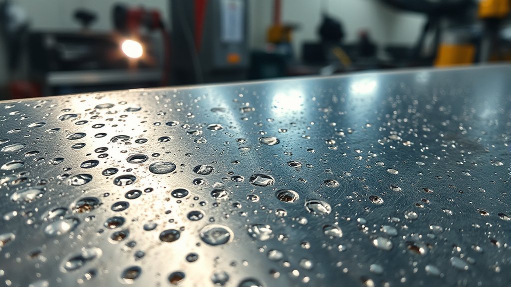
Bubbly welds usually mean gas became trapped in the metal as the weld cooled, creating a defect called porosity. The root cause is often dirty or damp material, interrupted shielding gas, the wrong gas or polarity, contaminated filler metal, or an unstable technique. Start with the simple checks before changing several machine settings at once.
Quick Answer
Your welds may look bubbly because contamination or poor shielding allowed gas to become trapped in the weld metal. Clean and dry the joint, confirm the correct wire, gas, and polarity, inspect the full gas path for leaks or blockages, and reset the welder from its chart before testing one adjustment at a time.
Key Takeaways
- Porosity is trapped gas in the weld metal, but a lumpy or rough bead may instead be spatter, cold lap, slag, or poor bead shape.
- Clean and dry the base metal, filler wire, filler rod, nozzle, and nearby joint area before changing machine settings.
- Check gas flow while gas is actually moving, then inspect the cylinder, regulator, hose, gun connection, diffuser, and nozzle.
- Voltage, wire-feed speed, amperage, gas flow, and stick-out are process-specific. Start with the machine chart, wire data, or approved welding procedure.
- Remove porous weld metal before rewelding. Safety-critical work may require inspection under the applicable drawing, code, or procedure.
At a Glance
| Time Required | About 15–45 minutes for basic diagnosis and test welds |
| Difficulty | Beginner to intermediate; qualified inspection may be needed for critical work |
| Tools Needed | Welding PPE, wire brush or grinder, nozzle pliers, approved cleaner, leak-detection solution, and matching scrap metal |
| Cost | Often $0–$25 for cleaning and basic consumables; damaged hoses, regulators, liners, tips, or gas cylinders cost more |
What’s in This Article
- Identifying Causes of Bubbly Welds
- Porosity or Another Weld Defect?
- Step-by-Step Bubbly Weld Troubleshooting
- How Shielding Gas Affects Bubbly Welds
- Contamination’s Impact on Weld Integrity
- Spotting Equipment Problems
- Adjusting Welding Parameters
- Effective Surface Preparation
- Controlling Environmental Factors
- Process-Specific Porosity Causes
- Alternative Welding Methods
- Bubbly Weld Troubleshooting Table
- When to Stop and Check the Weld
- Frequently Asked Questions
- Conclusion
- Sources
Identifying Causes of Bubbly Welds
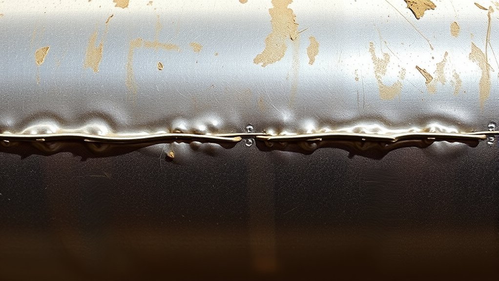
A bubbly weld bead commonly points to porosity: rounded cavities left when gas cannot escape before the molten metal solidifies. According to Miller’s MIG defect troubleshooting guidance, common causes include inadequate shielding, gas leaks, drafts, dirty material, excessive gun angle, and excessive wire extension.
Rust, oil, grease, paint, mill scale, moisture, cutting fluid, anti-spatter compound, and coatings can release gases or interfere with the weld pool. Shielding can also fail because the cylinder is empty, the valve is closed, the gas mixture is wrong, a hose is damaged, the gun is not fully seated, or the diffuser or nozzle is blocked.
Machine parameters can contribute, but porosity should not automatically be blamed on voltage. Excessive arc length, an unsuitable voltage-to-wire-speed balance, the wrong polarity, or poor wire feeding may make the arc unstable or reduce shielding. Begin with the machine chart rather than guessing at a universal voltage or wire-feed speed.
Check the work area as well. Wind, fans, open doors, or extraction placed too close to the arc can disturb gas-shielded processes. Keeping a clean workspace lowers contamination and fire risks, but cleanliness does not replace proper gas delivery or ventilation.
Change one variable at a time. When several settings and parts are changed together, you may hide the real cause without learning which correction solved it.
Porosity or Another Weld Defect?
Visible pinholes, rounded pits, or cavities in the bead are common signs of surface porosity. Porosity can also remain below the surface, so a smooth bead does not prove that a weld is sound.
Do not assume every rough or “bubbly” bead is porous. Use the appearance and behavior of the weld to narrow the problem:
| What You See | Likely Issue | First Checks |
|---|---|---|
| Round pinholes or cavities | Porosity | Gas delivery, contamination, moisture, gas type, angle, and stick-out |
| Loose metal droplets around the bead | Excessive spatter | Polarity, voltage balance, wire feeding, gas, surface condition, and technique |
| High rope-like bead with poor tie-in | Cold lap or lack of fusion | Heat input, travel speed, work angle, arc position, and joint preparation |
| Long grooves or tracks on flux-core welds | Gas marks or worm tracking | Voltage, electrode extension, wire condition, technique, and manufacturer guidance |
| Dark trapped lines after slag processes | Slag inclusion | Slag removal, joint access, angle, travel speed, and heat input |
| Uneven starts and stops without clear holes | Technique or wire-feed instability | Drive rolls, liner, contact tip, spool drag, work clamp, and trigger control |
If earlier welds were sound and porosity suddenly appears, identify what changed. Check the gas cylinder, material batch, wire spool, work location, weather, consumables, gun position, and machine setup. Understanding common causes of porosity helps, but a fixed inspection order is faster than random adjustments.
Step-by-Step Bubbly Weld Troubleshooting
1. Confirm the Process, Wire, Gas, and Polarity
Read the wire label, spool specification, machine chart, and owner’s manual. Confirm that the selected gas and polarity match the exact wire. Solid-wire mild-steel MIG commonly uses DCEP, while many self-shielded flux-core wires use DCEN. Gas-shielded flux-core wires often use DCEP, but the wire manufacturer’s instructions control.
Make sure the machine is not still configured for a different process. A polarity left over from self-shielded wire can produce a poor solid-wire MIG bead, and the wrong shielding gas can create instability, spatter, or porosity.
2. Clean and Dry the Material and Filler
Remove oil, paint, rust, scale, moisture, marking compounds, and coating from the joint and the nearby area. Clean the work-clamp location to bare metal. Inspect wire or filler rod for rust, dirt, oil, and condensation.
Cold metal brought into a warm, humid shop may collect condensation. Allow it to reach a dry condition before welding. Store filler metals according to the manufacturer’s instructions.
3. Test the Entire Gas-Delivery System
- Confirm supply: Make sure the correct cylinder is connected, contains gas, and has its valve open.
- Check flowing gas: Read the flowmeter while the trigger or purge function is supplying gas. A static reading does not prove that gas reaches the nozzle.
- Inspect for leaks: Check approved connection points with a suitable leak-detection solution. Replace damaged hoses or seals rather than patching them.
- Inspect the gun path: Confirm the gun is fully seated and examine its connection, O-rings, gas hose, diffuser, nozzle, and cable for damage or blockage.
- Listen and feel carefully: With the machine made safe according to its manual, verify that gas exits at the nozzle. Do not place your face in front of the nozzle.
4. Reset the Machine From an Authoritative Starting Point
Use the chart inside the welder, the owner’s manual, an approved welding procedure specification, the wire manufacturer’s data, or the machine’s automatic setup feature. Voltage and wire-feed speed cannot be reduced to one range that fits every machine and job.
Record the starting values. Make one small change, run a short bead on matching clean scrap, and compare the result. Returning to a known baseline prevents endless adjustment.
5. Check Technique on Matching Scrap
Keep a consistent contact-tip-to-work distance, work angle, travel angle, and travel speed. For common short-circuit MIG work, Miller lists a typical travel angle of 5–15 degrees and warns that excessive angle can cause spatter and arc instability. Follow the recommendation for your process and joint.
Hold the arc near the leading edge of the puddle. Avoid waving the gun far from the joint or stretching the wire beyond the nozzle. When the scrap weld becomes clean and repeatable, transfer the verified setup to the workpiece.
Pro Tip: Photograph the machine chart and write down successful settings for each wire, gas, thickness, and position. This creates a reliable starting library for future jobs without turning one setup into a universal rule.
How Shielding Gas Affects Bubbly Welds
Shielding gas protects the molten weld pool from the surrounding atmosphere. If coverage is interrupted, oxygen, nitrogen, and moisture can enter the weld zone and contribute to porosity.
Use the Correct Shielding Gas
The gas must match the material, wire, and transfer mode. For mild-steel MIG, common choices include an argon-carbon-dioxide blend or 100% carbon dioxide. Aluminum MIG commonly uses argon or an approved argon-helium blend. Stainless-steel gas selection depends on the wire and transfer mode.
Do not assume that a cylinder contains the correct gas because the connection fits. Read the cylinder label and wire specification.
Set Gas Flow While Gas Is Flowing
For indoor mild-steel MIG, Miller gives 20–25 CFH as one common setup example. That is not a universal specification. Nozzle size, gas type, current, process, joint geometry, welding position, and environmental conditions can require a different value.
Check the flowmeter while gas is moving through the gun. Too little flow leaves the puddle exposed. Too much flow can create turbulence, waste gas, and pull surrounding air into the shield.
Protect the Gas Shield From Drafts
Wind and drafts can break the shield even when the regulator shows the expected flow. Block unwanted crossflow with a suitable welding screen or move the work when practical. Gas-shielded MIG and TIG are difficult to protect in strong outdoor wind; self-shielded flux-core or stick may be better suited when the procedure permits.
Warning: Do not block required ventilation or trap welding fumes just to preserve shielding gas. Position local exhaust so it captures fumes without pulling the gas shield directly off the weld, and follow applicable workplace and confined-space requirements.
Gas-shielded flux-core welding still needs correct external gas when the wire requires it. Review this explanation of when flux-core welding requires shielding gas.
Contamination’s Impact on Weld Integrity
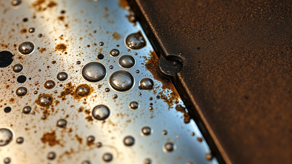
Oil, grease, paint, mill scale, cutting fluid, moisture, rust, adhesive, and anti-spatter residue can interfere with fusion or release gases into the weld pool. Contamination may come from the workpiece, filler metal, shielding-gas system, tools, gloves, or nearby processing.
Clean beyond the visible bead area because heat spreads outside the joint. A coating next to the weld can burn, contaminate the puddle, or create hazardous fumes even when the immediate groove looks bare.
Mild Steel
Solid MIG wire has limited tolerance for heavy rust, oil, paint, and scale. Remove coatings and contamination to bright metal where the weld and work clamp will contact the part. A sound setup starts with a clean electrical path and joint.
Aluminum
Aluminum is especially sensitive to hydrogen-related porosity. Remove grease and moisture with an approved method, then remove oxide with a dedicated clean stainless-steel brush or another procedure suitable for the alloy. Do not use a brush that has touched carbon steel.
Keep aluminum filler wire and rods clean and dry. Check the gas system carefully because a small leak or draft may produce widespread pinholes.
Galvanized and Coated Metals
Galvanized steel contains zinc. Heating zinc can produce zinc oxide fume, and OSHA identifies zinc exposure as a common cause of metal fume fever. Remove coating from the weld zone only with an appropriate procedure, control fumes at the source, use required PPE, and follow the coating manufacturer’s safety data and workplace rules. Learn more about zinc contamination and coating removal.
Warning: Never use chlorinated brake cleaner or another chlorinated solvent on or near a welding job. Heat and welding radiation can break down chlorinated hydrocarbons and form highly toxic phosgene. Read the product label and safety data sheet before using any cleaner.
Good preparation works together with proper shielding. This guide to MIG welding problems and gas-flow checks provides additional troubleshooting context.
Spotting Equipment Problems With Nozzles and Settings
Equipment faults can produce porosity even when the material and technique appear correct. Inspect the system from the cylinder to the arc rather than looking only at the regulator.
Products Worth Considering

Gel eliminates erratic operation with a film that will not clog orifices and threads on MIG nozzles and contact tips

APPLICATION METHOD: Enhance welding efficiency by dipping nozzles or contact tips in our specialized welding nozzle gel; reapply as needed for continuous protection and improved welding experience.

For MIG Welding Gun Torch & Lincoln Magnum 100L and Tweco Mini/#1
Nozzle Size Matters
The nozzle must be large enough and correctly positioned to cover the weld pool. A small, damaged, or heavily blocked nozzle can restrict or distort gas flow. Match its bore and contact-tip recess to the gun, current, wire, joint access, and manufacturer’s recommendations.
Remove spatter without damaging the nozzle or diffuser. Replace distorted or badly worn parts. Keep the recommended contact-tip-to-work distance because excessive distance weakens coverage, while an extremely short distance can increase spatter and damage consumables.
Inspect Gas Flow Rate and the Full Gas Path
- Read flow during operation: Use the trigger or purge function so the meter reflects flowing gas.
- Confirm the cylinder: Check the label, valve, remaining supply, regulator, and fittings.
- Inspect for leaks: Examine hoses, connections, seals, and the gun cable.
- Clean the gas path: Remove spatter from the nozzle and inspect the diffuser for blocked ports.
- Confirm gun installation: A loose or partly seated gun connection can leak or restrict gas.
- Avoid blind increases: Correct leaks, blockages, and drafts before raising flow beyond the recommended range.
Check Electrical Connections and Polarity
Inspect the work clamp, work lead, gun connection, power cable, and internal polarity leads. Attach the work clamp to clean metal. Loose or damaged connections can create erratic output, excess spatter, poor wire feeding, and inconsistent heat.
Solid-wire MIG commonly uses DCEP. Many self-shielded flux-core wires use DCEN, while gas-shielded flux-core wires often use DCEP. Always follow the wire label and machine manual because a general rule does not cover every electrode.
Inspect the Wire-Feeding System
Irregular wire feeding can make the bead surge, spit, or appear spotty. Check that:
- The contact tip matches the wire diameter and is not worn or burned.
- The liner is the correct size, clean, properly trimmed, and free of sharp bends.
- The drive rolls match the wire type and diameter.
- Drive-roll tension is high enough to feed without crushing or shaving the wire.
- The spool brake is not dragging or allowing the spool to overrun.
- The wire is clean, dry, and free from rust or oil.
Use the welder’s setup information and this wire-speed and voltage guide as supporting information, but give the machine chart and wire data priority.
Adjusting Welding Parameters to Reduce Porosity
Do not begin parameter tuning until the joint is clean and the correct gas, wire, polarity, and gas delivery have been confirmed. Machine adjustments cannot repair an empty cylinder, leaking hose, wet filler, or painted joint.
Products Worth Considering

High-quality: ARCCAPTAIN's ER70S-6 mig welding wire .030" meets industry standards(Net Weight: 10lbs), ensuring consistent performance, superior strength. With its smooth feeding and stable welding parameters, you can achieve optimal penetration, high deposition rates, and exceptional overall welding performance.

E71T-GS FLUX CORE WIRE: This self-shielding, AWS E71T-GS flux-cored wire excels due to its advanced core design, delivering exceptional arc stabilization and high feedability for effortless welding. The core also incorporates powerful deoxidizing agents, ensuring clean, reliable welds even when welding through light rust or mill scale.

ER308L WIRE: A low-carbon stainless steel wire engineered to minimize intergranular carbide precipitation. This enhances corrosion resistance without the need for stabilizers, making it ideal for critical applications.
Use the Machine Chart Instead of a Universal Voltage
There is no single 20–30-volt range that fits general MIG welding. The correct voltage depends on wire diameter, wire classification, base-metal thickness, gas mixture, joint design, welding position, transfer mode, and machine characteristics.
Start with the welder chart, owner’s manual, wire data sheet, or WPS. Then inspect the arc and bead:
- Voltage too low for the setup: The wire may stub, the bead may become high and narrow, and fusion may be poor.
- Voltage too high for the setup: The arc may become long, the bead may flatten excessively, spatter may increase, and shielding may become less reliable.
- Correct balance: The arc remains steady, the bead ties into both sides of the joint, and the wire does not repeatedly stub or burn back.
Balance Wire-Feed Speed With Voltage
Wire-feed speed controls welding current on a constant-voltage MIG machine. A feed speed that is too high for the selected voltage may drive the wire into the puddle. A feed speed that is too low may cause an overly long arc or burnback.
Do not use 250–300 inches per minute as a general target. Begin with the value specified for your exact wire and material thickness. Make small paired adjustments while testing on clean scrap.
Check Travel Speed, Angle, and Stick-Out
Moving too slowly can create a large, overheated puddle and excessive buildup. Moving too quickly can leave a narrow bead with poor tie-in. Excessive gun angle or wire extension can expose the puddle to air and destabilize the arc.
Maintain the recommended welding parameters and arc length. Keep your hand position steady enough that the gas shield remains centered over the puddle.
Note: A sound test bead should be evaluated for more than appearance. Check bead shape, tie-in, penetration appropriate to the joint, and any acceptance requirements that apply to the finished part.
Effective Surface Preparation Techniques
Surface preparation removes materials that can form gas, block fusion, contaminate filler metal, or interfere with the work connection. Use a process suitable for the base metal and coating.
Clean metal gives the shielding gas, arc, and filler metal the best chance to create a sound weld, but preparation must be combined with correct process settings and fume control.
- Identify the base metal and coating: Determine whether the part is bare steel, galvanized, painted, plated, stainless, aluminum, cast material, or an unknown alloy.
- Review hazards: Check labels and safety data sheets before grinding, heating, or welding coatings and cleaners.
- Remove loose contamination: Brush or wipe away dirt and debris before grinding so it is not driven into the surface.
- Remove coatings and scale: Grind, sand, machine, or brush the weld zone using a suitable method.
- Degrease safely: Use a non-chlorinated product approved for the metal and welding operation, then allow the area to dry fully.
- Use dedicated tools where needed: Keep aluminum and stainless-steel cleaning tools separate from carbon-steel tools.
- Clean the clamp location: Attach the work clamp to sound, bare metal.
- Inspect filler and consumables: Replace rusty wire, contaminated rods, damaged tips, or clogged nozzles.
- Run a test: Weld matching scrap before committing to the final joint.
Clean tools and nozzles matter too. Spatter, oil, and damaged consumables can undo careful workpiece preparation.
Controlling Environmental Factors During Welding
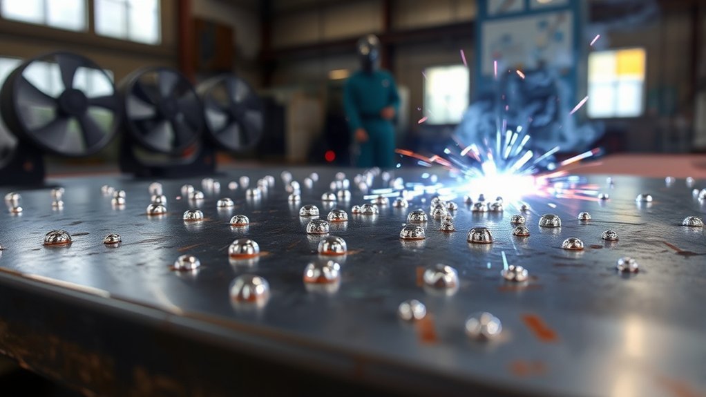
Humidity, condensation, rain, snow, wind, dust, and temperature changes can all affect welding. Damp filler or cold metal may carry moisture into the weld zone. Dust or grinding debris can settle on a prepared joint before welding begins.
Store wire, electrodes, rods, and base materials in clean, dry conditions. Follow manufacturer storage requirements, especially for moisture-sensitive electrodes and filler metals.
Control cross-drafts around gas-shielded welding. Move fans that blow directly across the arc, close unnecessary doors, or use a welding screen when safe. Do not simply increase gas flow until the problem disappears, because turbulence may make porosity worse.
Use proper ventilation systems and fume controls. Position extraction to capture fumes without stripping shielding gas from the puddle or placing fumes in the welder’s breathing zone.
Pro Tip: When porosity appears only at the beginning of a weld, purge the gas line as directed by the machine manual, check for an excessive start surge, and confirm that the nozzle is over the joint before the arc starts.
Process-Specific Porosity Causes
MIG or GMAW
Start with shielding gas, contamination, nozzle condition, gun seating, leaks, polarity, excessive angle, and excessive stick-out. Also inspect wire feeding because a worn tip or damaged liner may make the arc surge.
TIG or GTAW
TIG porosity often points to dirty or damp base metal, contaminated filler rod, leaks, restricted gas flow, a damaged torch, excessive arc length, or a draft. A contaminated tungsten may also destabilize the arc. Miller’s TIG troubleshooting guide recommends checking moisture, surface cleanliness, connections, hoses, and shielding flow.
Use the correct cup, gas lens when appropriate, tungsten preparation, polarity, and gas for the material. Do not apply a MIG gas-flow value to TIG without checking the torch and manufacturer guidance.
Self-Shielded Flux Core
Self-shielded flux-core wire does not use an external gas cylinder, so wind is less likely to cause loss of an external gas shield. However, porosity can still result from contamination, moisture, incorrect polarity, wrong electrode extension, unsuitable technique, or damaged wire.
Use the polarity, drag angle, electrode extension, and parameter range printed for the exact wire. Remove slag between passes.
Gas-Shielded Flux Core
Gas-shielded flux core can suffer from both flux-related and external shielding problems. Check the required gas mixture and flow, polarity, nozzle, gas path, electrode extension, voltage, and wire condition. Long surface tracks may be gas marks rather than round MIG-style pinholes.
Stick or SMAW
Stick-welding porosity can come from damp or damaged electrodes, dirty metal, an arc that is too long, incorrect amperage, or poor technique. Store and recondition electrodes only according to their manufacturer’s directions and any applicable welding procedure.
Alternative Welding Methods for Complex Materials
Some materials and joints are difficult to repair with a basic MIG setup. A different joining process may improve control, but changing processes does not remove the need for correct design, preparation, filler selection, ventilation, and qualification.
- Brazing: Brazing melts a filler metal without melting the base material. It can suit some dissimilar-metal or heat-sensitive assemblies, but it is not a substitute where a drawing or repair procedure requires a fusion weld.
- TIG welding: TIG offers precise heat and filler control for thin material, aluminum, stainless steel, and detailed joints, but cleanliness and shielding remain critical.
- Laser welding: Laser welding is an advanced process used for concentrated heat input, automation, and low-distortion applications. It requires specialized equipment, joint preparation, and process control.
- Plasma arc welding: Plasma arc welding provides a concentrated arc and precise control in suitable industrial applications. Correct joint design and fillet weld sizing still govern the finished joint.
Do not select a repair process based only on which one produces the smoothest bead. Consider the base-metal alloy, loading, service temperature, corrosion, fatigue, joint geometry, and applicable repair requirements.
Bubbly Weld Troubleshooting Table
Experienced welders usually begin with the most likely variables and work outward from the arc. The table below turns that practical approach into a repeatable diagnosis.
| Symptom | Likely Causes | Recommended Check |
|---|---|---|
| Pinholes across the entire MIG bead | No gas, wrong gas, major leak, severe contamination, or strong draft | Stop and verify gas supply, flow at the nozzle, cylinder label, hose, gun, nozzle, and surface |
| Porosity appears after several good welds | Cylinder running out, new contamination, damaged consumable, heat-related hose problem, or changing draft | Identify what changed and inspect the system from cylinder to nozzle |
| Porosity only at starts | Air or moisture in the line, delayed gas delivery, excessive gas surge, or poor gun placement | Use the purge function, inspect gas timing and connections, and start with the nozzle correctly positioned |
| Porosity only at stops or craters | Abrupt termination, poor crater filling, or loss of shielding before solidification | Use the specified crater-fill and post-flow technique |
| Spotty arc with heavy spatter | Wrong polarity, poor work connection, unstable wire feeding, incorrect parameter balance, or contamination | Confirm polarity, clamp contact, tip, liner, drive rolls, wire condition, and machine chart |
| Porosity mainly outdoors | Shielding gas blown away | Move indoors, use safe wind protection, or select an approved wind-tolerant process |
| Recurring porosity in aluminum | Hydrocarbon contamination, moisture, oxide, dirty filler, or shielding leak | Clean with an aluminum-approved procedure and inspect filler storage and gas delivery |
Steady travel speed and consistent electrode extension are important, but isolated cavities should not simply be drilled, covered with tacks, or welded over. Those actions can hide the defect without removing it. Understanding proper stick-out distance and MIG equipment checks can help stabilize the arc.
When to Stop and Check the Weld
Stop welding when porosity continues after the basic checks, when the defect grows worse, or when you cannot identify the base metal, coating, wire, gas, or required procedure. Continuing may bury cavities under later passes and make repair more difficult.
Porous weld metal generally must be removed to sound material before rewelding. Grind, machine, or cut out the affected area using a method allowed for the part. Clean it again, correct the root cause, and test the revised setup on matching scrap.
Visual inspection can identify surface porosity but cannot prove that the interior is sound. The acceptable amount, size, distribution, and location of porosity depend on the drawing, code, welding procedure, service, and inspection method.
Get qualified help for structural members, lifting equipment, pressure-containing parts, vehicle suspension or steering components, trailers, roll cages, gates, critical machinery, and any weld whose failure could injure someone. A welding inspector or engineer may require penetrant, magnetic-particle, ultrasonic, radiographic, bend, or destructive testing.
Warning: Welding produces intense light, heat, sparks, electrical hazards, fumes, gases, and fire risk. Remove combustibles, wear suitable eye, face, hand, body, and respiratory protection, follow the machine manual, and use ventilation that meets the material and workplace requirements.
Frequently Asked Questions
How do you smooth welds without causing more bubbles?
Correct the source of the porosity before grinding for appearance. Remove defective metal to a sound surface, clean and dry the joint, confirm gas delivery and settings, and then reweld. Grinding the top smooth without removing subsurface cavities can hide the defect.
Why is my weld lumpy?
A lumpy bead may come from unstable wire feeding, incorrect voltage-to-wire-speed balance, slow or uneven travel, poor gun angle, excessive filler, cold lap, or contamination. Look for actual rounded holes before calling it porosity.
What causes bubble gum welds?
“Bubble gum weld” is an informal description rather than a technical defect. It may refer to a tall, uneven, poorly fused, spattered, or porous bead. Check fusion, bead shape, gas coverage, contamination, travel speed, wire feeding, polarity, and machine settings.
Why are my MIG welds spotty?
Spotty MIG welds commonly result from interrupted wire feeding, a worn contact tip, a dirty liner, incorrect drive-roll tension, wrong polarity, poor work-clamp contact, contamination, or unstable shielding. Inspect the wire path and electrical circuit as well as the gas system.
Can you weld over porosity?
Do not cover known porosity without removing the defective weld metal and correcting its cause. A new pass may seal surface holes while leaving cavities inside. Grind or cut back to sound metal, prepare the joint again, and reweld under a verified setup.
What shielding-gas flow should I use for MIG welding?
Use the machine, wire, and gas recommendations. For indoor mild-steel MIG, 20–25 CFH is one common manufacturer example, but it is not universal. Read the meter while gas is flowing and correct leaks, blockages, or drafts instead of automatically increasing flow.
Why does porosity appear only at the start of my weld?
Start porosity may come from air or moisture in the gas line, delayed shielding, a gas surge, an improperly positioned nozzle, or contamination at the tack or starting point. Purge and inspect the gas system according to the machine manual.
Can wind cause bubbly MIG or TIG welds?
Yes. Even a noticeable indoor draft can move shielding gas away from the puddle. Move the work, block crossflow safely, or use an approved process better suited to the conditions. Do not defeat required fume ventilation to protect the gas shield.
Conclusion
Bubbly welds usually trace back to trapped gas, but the visible bead must first be identified correctly. Pinholes suggest porosity, while a lumpy or spotty bead may involve spatter, cold lap, slag, unstable wire feeding, or poor technique.
Work in a fixed order: confirm the process, wire, gas, and polarity; clean and dry the joint; inspect the gas system from cylinder to nozzle; reset the machine from an authoritative chart; and test one change at a time on matching scrap. Remove defective weld metal before rewelding, and obtain qualified inspection whenever the joint is structural or safety-critical.
Sources
- Miller — Tips for Troubleshooting Common MIG Weld Defects — porosity, gas coverage, nozzle, drafts, stick-out, gun angle, and contamination
- Miller — Understanding the Basics of MIG Welding for Mild Steel — polarity, cleaning, common indoor gas-flow example, settings, angles, and stick-out
- Miller — Guide to TIG Welding Basics — TIG contamination, moisture, gas, hoses, tungsten, and arc troubleshooting
- OSHA — Welding, Cutting, and Brazing General Requirements — ventilation, hazardous fumes, labels, and workplace controls
- OSHA — Respiratory Irritation and Systemic Poisoning During Welding — zinc oxide, galvanized steel, toxic-metal fumes, and exposure controls
- ATSDR — Phosgene Medical Management Guidelines — phosgene formation from heated chlorinated compounds and chlorinated-solvent welding hazards



