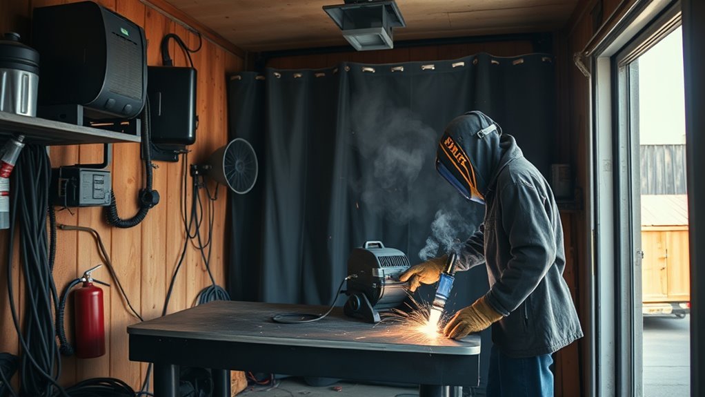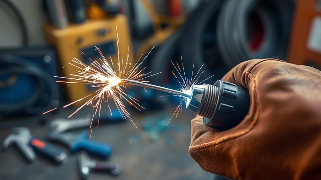
When MIG wire sticks in the contact tip, the problem is usually burnback or interrupted wire feeding—not the wire randomly “welding itself” inside a healthy gun. The fastest fix is to identify whether the wire fused at the tip, stalled in the liner, birdnested at the drive rolls, or simply stubbed into the work because the machine settings were out of balance.
Quick Answer
MIG wire most often sticks in the contact tip when the wire burns back faster than it feeds. Common causes include wire speed that is too low for the voltage, a slipping or mismatched drive roll, excessive spool drag, a dirty or damaged liner, a worn tip, or holding the gun too close to the work.
Key Takeaways
- A wire fused inside the contact tip is burnback; wire piled up near the drive rolls is birdnesting.
- Check the tip, gun-cable position, spool brake, drive rolls, liner, and wire condition before changing several machine settings.
- For short-circuit MIG with solid wire, 3/8 to 1/2 inch of electrode extension is a common starting range, but the welder chart and wire procedure take priority.
- Use the correct drive-roll groove, liner, and contact tip for the wire type and diameter.
- A poor work-clamp connection can destabilize the arc, but it does not usually create a mechanical feed restriction by itself.
At a Glance
| Time Required | About 10–30 minutes for basic inspection and adjustment |
| Difficulty | Basic to intermediate |
| Tools Needed | PPE, side cutters, MIG pliers, correct wrench, clean brush, correct-size tip cleaner, and the welder manual; a multimeter is optional |
| Cost | Often no cost for adjustment; replacement tip, liner, drive roll, or wire cost depends on the gun and welder model |
What’s in This Article
- Identify the Type of Wire Sticking
- Common Causes of MIG Wire Sticking
- How to Fix Erratic Wire Feeding Issues
- Why Tip Stick-Out Matters for Welding
- How to Identify and Fix Work-Clamp Issues
- Best Practices for Wire Maintenance
- Understanding Wire-Feed Speed and Voltage
- Selecting the Right Wire, Tip, Liner, and Drive Roll
- Special Case: Aluminum Wire
- Regular Maintenance Steps
- When the Welder Needs Service
- Frequently Asked Questions
- Conclusion
- Sources
Identify the Type of Wire Sticking First
Different symptoms point to different faults. Check what the wire is doing before you tighten a drive roll or turn a control.
| Symptom | What It Usually Means | First Check |
|---|---|---|
| Wire is fused inside the contact tip | Burnback | Tip condition, wire speed versus voltage, feed slippage, and electrode extension |
| Wire piles up near the drive rolls | Birdnesting caused by downstream resistance | Contact tip, liner, cable bends, and drive-roll pressure |
| Wire repeatedly hits the plate and pushes the gun back | Stubbing from too much wire feed for the voltage, excessive stick-out, or poor arc initiation | Welder chart, voltage, wire speed, work connection, and polarity |
| Wire surges with the arc off | Mechanical feed problem | Spool brake, drive rolls, liner, gun cable, and tangled wire |
Warning: Switch off and unplug the welder before touching the contact tip, liner, drive rolls, spool, or internal feed parts. Close the shielding-gas cylinder when the machine will be open for service. Only re-energize the welder for a controlled feed test after guards are restored, the gun is aimed away from people, and the wire cannot contact the work or any conductive object.
Common Causes of MIG Wire Sticking
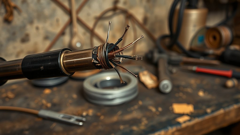
When you weld with MIG, the wire must move steadily from the spool, through the drive system and liner, and out of the contact tip. Low wire speed relative to the selected voltage can let the arc climb back toward the tip. This is called burnback. A worn, distorted, dirty, or spatter-blocked contact tip can make the problem worse by disrupting current transfer or adding drag.
Rusty or contaminated wire can also interfere with smooth feeding. Rust, dirt, metal shavings, and moisture can add drag or carry debris into the liner. A blocked, kinked, incorrectly sized, or improperly trimmed torch liner can restrict wire flow and trigger slippage, birdnesting, or burnback. Lincoln Electric and Hobart Brothers both list the contact tip, drive rolls, liner, gun cable, and feeder setup among the main areas to inspect for wire-delivery faults. Lincoln Electric’s MIG troubleshooting guidance and Hobart Brothers’ wire-feeding guide provide manufacturer-level checks.
Improper drive-roll tension can create the same problem. Too much pressure may deform solid wire, crush tubular wire, or peel material into the liner. Too little pressure lets the rolls slip. Spool-hub tension can also be too high, while a nearly loose hub can let the spool coast and tangle. Understanding proper wire feed speed can help you avoid these feeding problems.
Burnback is usually the result of an arc-setting imbalance or a momentary loss of wire movement. The contact tip is where the symptom appears, but the restriction may be anywhere from the spool to the end of the gun.
How to Fix Erratic Wire Feeding Issues
Use this troubleshooting order so one change does not hide another fault.
- Make the machine safe. Turn it off, unplug it, close the gas cylinder, and let hot gun parts cool. Cut the wire behind any fused section before removing the contact tip.
- Inspect the contact tip. Replace it if the wire has fused in the bore, the hole is visibly enlarged or oval, the threads are damaged, or a correct-size tip cleaner cannot clear light debris without force. Do not drill or aggressively ream the bore larger.
- Check the gun cable. Lay it as straight as practical. Tight loops, sharp bends, damage, or an overly long gun increase feed resistance.
- Check the spool and hub brake. Make sure the spool is installed in the correct direction, the wire is not crossed under another turn, and the spool rotates without binding. Set only enough hub drag to stop the spool from coasting after the trigger is released.
- Verify the drive rolls. Match the groove diameter to the wire. Use the roll style specified for the consumable—commonly a V-groove for solid steel wire, a knurled groove for many cored wires, and a U-groove for soft aluminum wire.
- Set drive-roll pressure correctly. Start low and increase only until the wire feeds without slipping. Do not use extra pressure to force wire through a blocked tip or liner.
- Inspect the liner and guides. Confirm that the liner matches the wire diameter and type, is trimmed to the gun maker’s specification, and is not kinked, packed with debris, or separated from the inlet and outlet guides. Improper liner length can cause feeding problems. Tregaskiss explains why liners that are too short or too long can cause birdnesting and poor feeding.
- Inspect the wire. Replace wire that is rusty, kinked, visibly dirty, poorly wound, or damaged. Do not try to restore rusty wire with oil or household cleaners.
- Return to the setup chart. Confirm wire diameter, material thickness, shielding gas, polarity, voltage, and wire-feed speed. The proper settings can help prevent poor wire feeding and burnback.
- Run a controlled feed test. With the nozzle and contact tip removed, guards closed, full PPE on, and the gun aimed into a safe nonconductive area, re-energize the machine only long enough to check whether bare wire feeds smoothly. Switch off and unplug again before reinstalling parts. If the feed is smooth without the tip but binds with the correct new tip, inspect tip alignment and compatibility.
- Make one test weld on scrap. Use the recommended stick-out and adjust one setting at a time. If the wire burns back, first verify feed consistency, then make small setting changes within the welder chart.
Pro Tip: Mark the original drive-roll pressure and machine settings before changing them. If the problem remains, you can return to the known starting point instead of chasing several changes at once.
Products Worth Considering

Package list: 30 pieces of 0.030 inch mig welder tips.

20Pcs Contact Tip .023'' Ø0.6mm

1. Package Includes 30 Premium Quality .023” (Ø0.6mm)welding Tips.
Why Tip Stick-Out Matters for Welding
Electrode extension, often called wire stick-out, is the wire length from the end of the contact tip to the arc. It affects current, wire heating, arc behavior, penetration, and contact-tip temperature. Holding the tip too close can increase radiant heat at the front end and make accidental tip-to-work contact or burnback more likely.
For short-circuit MIG with solid wire, a common starting range is about 3/8 to 1/2 inch. Miller also gives 3/8 inch as a general starting point for mild-steel MIG technique, while other transfer modes and cored wires may require a longer extension. Follow the chart inside your welder, the wire data sheet, and the gun setup rather than treating one number as universal. See Miller’s mild-steel MIG basics for a manufacturer example.
A stick-out that is too short can overheat the gun end and promote spatter or tip contact. A stick-out that is too long can reduce current, make the arc less stable, and cause the wire to stub into the work. Check the distance often and keep your hand position steady. Correct polarity also matters because solid gas-shielded wire and self-shielded flux-cored wire commonly use different polarity requirements.
Note: Nozzle position and wire stick-out are not the same measurement. The contact tip may be flush, protruding, or recessed inside the nozzle, so measure electrode extension from the contact tip—not automatically from the nozzle.
How to Identify and Fix Work-Clamp Issues
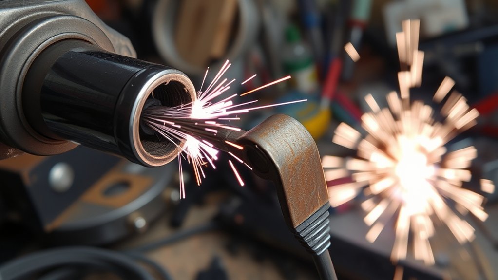
The part often called the “ground clamp” is more accurately the work clamp. It completes the welding circuit through the work lead. A poor connection can cause hard starts, an unstable arc, intermittent output, excess spatter, or wire stubbing. It is worth checking, but it usually does not cause a mechanical restriction inside the contact tip or liner.
- Attach the work clamp to clean metal: Connect it directly to the workpiece or to a clean metal table with a reliable conductive path. Avoid paint, mill scale, rust, grease, and loose fixtures.
- Inspect the clamp and cable: Check the jaws, spring pressure, cable, lugs, and machine connection for heat damage, looseness, broken strands, corrosion, or discoloration.
- Clean contact points: Remove contamination from the clamp area without damaging the part. A clamp attached to a clean area close to the weld often gives the most reliable path.
- Use a meter only as a basic check: With the welder unplugged, a continuity test can reveal an open circuit, but a near-zero unloaded reading does not prove that the connection will carry welding current without voltage drop. Do not measure resistance on an energized welding circuit.
- Recheck arc behavior: If the feed is mechanically smooth but the wire still stubs or the arc cuts in and out, inspect the work connection, polarity, output connections, and machine settings before replacing more gun parts. Proper wire quality can also help reduce feed trouble.
Best Practices for Wire Maintenance
Clean, undamaged wire feeds better than rusty or contaminated wire. Inspect the spool for rust, dirt, moisture, crossed turns, dents, and kinks before each welding session. Good clean storage practices limit corrosion and keep debris out of the feed path.
Store wire in a dry indoor location and keep it covered when it is not in use. A sealed container or clean bag can help during long storage, especially in a humid shop. Do not bake solid MIG wire or add oil unless the filler-metal manufacturer provides a specific procedure. If you also use stick electrodes, proper oven storage guidelines are different and should not be applied automatically to MIG wire.
Regular Wire Inspection
Regular wire inspection helps prevent feed problems before they stop your weld. Follow these checks:
- Inspect the exposed wire and spool for rust, dirt, kinks, loose wraps, or contamination.
- Store welding wire in a clean, dry place to limit moisture and debris.
- Do not feed visibly rusty or oily wire through the gun. Cut off a small contaminated outer section only when the remaining wire is clean and the manufacturer allows it; replace the spool when corrosion is widespread.
- Check that the spool lines up with the inlet guide and rotates without binding or excessive coast.
- Keep the wire end controlled during spool changes so it cannot spring loose and cross under another wrap.
Clean Storage Practices
Inspection helps, but storage matters just as much. Keep wire away from rain, condensation, grinding dust, chemicals, and dirty work surfaces. Use a dry cleaning pad or felt wiper only when the wire or equipment manufacturer approves it. Added lubricant can carry contaminants into the liner and contact tip.
| Action | Frequency | Purpose |
|---|---|---|
| Inspect wire spools | Before each use | Find rust, dirt, crossed turns, or damage |
| Clean the spool compartment | As needed | Keep grinding dust and debris out of the feed path |
| Use sealed dry storage | During extended storage | Limit moisture and contamination |
| Label opened spools | When stored | Track wire type, diameter, and condition |
| Maintain a clean feed area | Daily in active use | Prevent liner and tip contamination |
Understanding the Role of Wire-Feed Speed and Voltage
Wire-feed speed and voltage work together in MIG welding. On a typical constant-voltage machine, wire-feed speed strongly affects welding current, while voltage mainly affects arc length and bead shape. The correct pair depends on wire diameter, material thickness, transfer mode, shielding gas, and joint.
If wire speed is too low for the selected voltage, the arc can consume the wire faster than the feeder supplies it, increasing burnback risk. If wire speed is too high for the voltage, the wire can drive into the puddle or plate and create a harsh, irregular arc. A slipping feeder can imitate low wire speed even when the dial setting looks correct.
- Start with the machine chart: Use the door chart or owner’s manual for the exact wire, gas, and material thickness.
- Verify actual feeding: A correct dial setting cannot overcome drive-roll slip, spool drag, a blocked liner, or a bad tip.
- Adjust one control at a time: Make small changes and test on scrap of the same thickness and joint type.
- Check burnback controls: Some machines have an adjustable burnback or run-in setting. Return it to the manual’s recommended baseline before using it to mask a feed fault.
- Watch the weld, not only the sound: A steady arc is useful feedback, but bead shape, fusion, penetration, and spatter also matter. Understanding the importance of amperage can help you understand why wire-feed changes affect output, although stick-welding settings do not transfer directly to MIG.
Pro Tip: If burnback starts suddenly without any control changes, suspect a feed interruption first. A new tip or higher wire-speed setting may hide the symptom briefly while the real blockage remains.
Selecting the Right Wire, Tip, Liner, and Drive Roll
Selecting compatible feed parts helps the wire move smoothly through the gun. Match the wire diameter to the contact tip’s marked size unless the gun, wire, or tip manufacturer gives a different approved combination. For example, 0.035-inch wire normally uses a contact tip marked for 0.035-inch wire. The tip bore is manufactured with the clearance needed for that wire; you should not create clearance by drilling it.
An oversized tip can reduce electrical contact and arc control, while an undersized or damaged tip can bind the wire. Use a larger marked tip only when the manufacturer specifically allows it for the wire alloy, application, or thermal expansion. Proper flux-core wire selection also affects drive-roll choice, polarity, stick-out, and feed quality.
Products Worth Considering
1. Package Includes 30 Premium Quality .035” (Ø0.9mm)welding Tips.

【25-Pack High-Precision Contact for Miller Mig Tips】You will get 25 pieces of premium. 035" (0.9mm) MIG welding contact for Miller tips in one pack, for miller gun tips sufficient quantity to meet your daily welding replacement needs and avoid the trouble of frequent purchases for miller mig tip

Premium quality Lincoln/Tweco style standard 11-30 (0.030") contact tips for 100L and Mini MIG guns
Wire Size Compatibility
Wire size compatibility includes more than the tip. Check the complete path:
- Match the contact tip: Use the nominal tip size specified for the wire diameter and alloy.
- Match the liner: Use a liner with the correct diameter range and material for the wire.
- Match the drive-roll groove: Use the correct groove diameter and style for solid, cored, or soft wire.
- Align the guides: Keep inlet and outlet guides close enough to prevent the wire from wandering, without letting them touch the rolls.
- Follow manufacturer specifications: Check the welder, feeder, gun, wire, and consumable guidance before changing sizes.
Tip Size Selection
Correct tip size supports stable current transfer with low feeding resistance. A smaller-than-specified tip can pinch the wire. A larger tip is not a routine cure for poor feeding because it can let the wire wander and interrupt electrical contact.
| Wire Diameter | Usual Marked Tip Size | Effect on Performance |
|---|---|---|
| 0.030 in | 0.030 in | Standard nominal match when approved for the gun and wire |
| 0.035 in | 0.035 in | Standard nominal match for many steel-wire setups |
| 0.045 in | 0.045 in | Standard nominal match when the feeder, liner, and gun support it |
| 0.030 in | 0.035 in | Not a default match; use only when the tip or wire manufacturer expressly specifies it |
Always check the manufacturer’s specifications before changing tip size. Test on scrap metal first so you can confirm smooth feeding and stable arc control.
Performance Impact Factors
The right wire and consumable combination can improve arc stability and reduce burnback. Focus on these areas:
- Diameter compatibility: Match the marked tip, liner range, and drive-roll groove to the wire.
- Wire type: Solid steel, stainless, cored wire, and aluminum may need different rolls, liners, polarity, and gun systems.
- Arc stability: Replace a worn tip when the bore is elongated, current transfer is erratic, or burnback has damaged it.
- Feed-path alignment: Correctly seated guides, liner, diffuser, and tip reduce sudden changes in resistance.
- Maintenance: Clean external spatter and replace damaged consumables before they create drag or poor current transfer.
Use undamaged wire from a traceable supplier and keep the spool label. Clean wire and matched consumables give you a better chance of steady MIG welding.
Special Case: Aluminum Wire
Soft aluminum wire magnifies feeding faults because it has less column strength than steel wire. A standard long push-only gun may birdnest even when it feeds steel well. Depending on the machine and job, use the approved U-groove rolls, compatible liner, aluminum contact tip, short straight gun cable, spool gun, or push-pull system.
Miller recommends matching the contact tip, drive rolls, and liner to the aluminum wire diameter and checking drive-roll tension when burnback or birdnesting occurs. It also warns against holding the tip closer than recommended because reflected heat can promote burnback. See Miller’s aluminum MIG guide.
Regular Maintenance Steps to Prevent Sticking
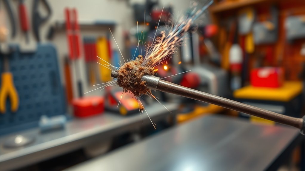
Regular maintenance helps prevent wire sticking in MIG welding. Inspect the contact tip, nozzle, diffuser, and gun connection often. Spatter and buildup can interfere with shielding gas, wire movement, or current transfer.
Replace worn contact tips before they cause erratic current transfer or repeated burnback. Check the liner for dirt, metal shavings, kinks, incorrect length, or damage. Follow the gun maker’s cleaning method; replace the liner when wire does not feed smoothly or when a blockage cannot be cleared safely.
Set drive-roll pressure with care. Too much pressure can deform wire or create debris, while too little pressure can cause slipping. A manufacturer-approved dry felt wiper can remove light dust in some systems, but do not soak it with oil or add a lube pad unless the filler-metal maker permits it. Hobart Brothers notes that excess added lubricant can clog liners, tips, and diffusers.
Keep the gun cable as straight as practical, check the spool hub, and clean the feeder compartment without blowing debris into electrical components. These habits reduce downtime and help your welder run smoothly. A stable arc also helps you get more consistent results.
| Maintenance Item | Check | Action |
|---|---|---|
| Contact tip | Burnback, oval bore, loose threads, heavy spatter | Clean light external buildup or replace |
| Liner | Drag, debris, kinks, wrong size or length | Clean only as directed or replace |
| Drive rolls and guides | Wrong groove, wear, debris, poor alignment | Clean, align, or replace |
| Spool and hub | Binding, excessive coast, crossed wire | Correct loading and hub tension |
| Work lead and clamp | Loose, hot, corroded, or damaged connection | Clean, tighten, repair, or replace |
When the Welder Needs Service
Stop troubleshooting at the consumable level and arrange qualified service when the drive motor does not turn, feed speed surges with a straight cable and no tip installed, the trigger or contactor behaves unpredictably, the machine repeatedly trips or overheats, electrical connections discolor or smell burned, or the output cuts in and out after external connections are cleaned and tightened.
Do not open the power-source cabinet unless the owner’s manual authorizes the task and you are qualified to work around stored electrical energy. Capacitors can remain hazardous after the machine is unplugged.
Warning: Welding exposes you to hot metal, ultraviolet radiation, electric shock, fire, noise, and hazardous fumes. Wear proper eye, face, hand, body, and hearing protection; provide suitable ventilation; keep combustibles away; and follow the welder and consumable manuals. OSHA lists fumes, UV radiation, burns, eye damage, and electrical shock among the main welding hazards. Review OSHA’s welding hazard guidance.
Frequently Asked Questions
Why Does My MIG Wire Keep Sticking to the Tip?
The wire is usually burning back into the contact tip because it is being consumed faster than it feeds, or because the feed pauses. Check wire-feed speed versus voltage, contact-tip damage, drive-roll slip, spool drag, liner resistance, gun-cable bends, wire condition, and stick-out. A poor work connection can also make arc starting unstable.
Can You Lubricate MIG Wire?
Do not add oil or a general-purpose lubricant to MIG wire. Welding wire is manufactured with a controlled surface condition, and extra lubricant can carry dirt into the liner, tip, and gas diffuser. Use a cleaner or lube pad only when the wire or equipment manufacturer specifically approves it.
How Do You Unclog a MIG Welding Tip?
Turn off and unplug the welder, let the gun cool, cut the wire behind the damaged section, and remove the tip. Use the correct-size tip cleaner only for light debris. Replace the tip if wire has fused in the bore, the opening is enlarged or oval, the threads are damaged, or cleaning requires force. Never use a drill bit to enlarge the hole.
Why Does My Welding Wire Keep Jamming?
Common causes include a blocked tip, dirty or kinked liner, tight gun-cable bends, excessive spool-brake drag, crossed wire on the spool, mismatched drive rolls, too much or too little roll pressure, rusty wire, and misaligned guides. If wire piles up near the drive rolls, look for resistance farther downstream.
Should I Replace the Contact Tip if the Wire Keeps Sticking?
Yes, replace it when burnback has fused wire inside, the bore is worn or oval, the tip is loose or heat-damaged, or correct cleaning does not restore free movement. Also fix the feed or setting problem that caused the burnback, or the new tip may fail again.
Why Does the Wire Feed but Keep Hitting the Metal?
That symptom is usually stubbing rather than a tip jam. Compare voltage and wire speed with the machine chart, shorten an excessive stick-out, clean and tighten the work connection, verify polarity, and confirm that the arc starts consistently. Do not keep increasing drive-roll pressure unless the rolls are actually slipping.
How Tight Should MIG Drive Rolls Be?
Use the lowest pressure that feeds the wire without slipping during welding. Start with low pressure and increase it gradually according to the feeder manual. If extra pressure is needed to push through the gun, inspect the tip, liner, guides, cable bends, and spool brake instead of crushing the wire.
Safety Disclaimer: Welding involves heat, electricity, fumes, ultraviolet radiation, fire risk, and bright arc light. Use proper personal protective equipment, ventilation, and fire controls; follow your welder and consumable manuals; and ask a qualified welding professional or service technician for help when the fault involves internal electrical parts.
Conclusion
MIG welder wire usually sticks in the contact tip because the wire burns back or the feed system pauses under load. Start with the easy checks: tip condition, straight gun cable, spool movement, drive-roll type and pressure, liner condition, wire quality, machine chart, stick-out, polarity, and work-clamp contact. Change one item at a time and test on scrap. Clean, correctly matched parts and balanced settings prevent most repeat failures.
Sources
- Lincoln Electric — MIG Problems and Remedies — contact-tip, liner, drive-roll, cable, and wire-delivery troubleshooting.
- Hobart Brothers — Wire Feeding Issues? Consider These Common Causes First — drive-roll selection and pressure, liner faults, tip wear, cable routing, and lubricant cautions.
- Miller — Understanding the Basics of MIG Welding for Mild Steel — general MIG technique and electrode-extension guidance.
- Miller — How to Successfully MIG Weld Aluminum — aluminum feed systems, burnback, birdnesting, tip distance, and matched consumables.
- Tregaskiss — Tips for Proper Liner Installation — liner length, alignment, birdnesting, and feed performance.
- OSHA — Welding, Cutting, and Brazing: Hazards and Solutions — welding fumes, radiation, burns, eye damage, electrical shock, and protective practices.