
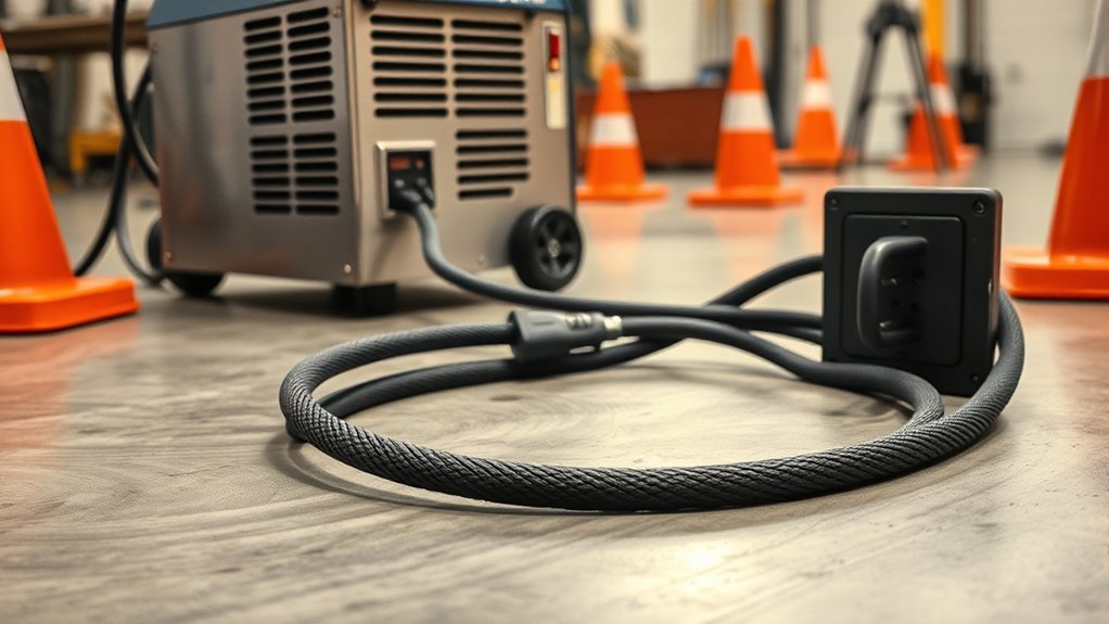
A welding extension cord is part of the welder’s input-power system, so choosing one by color, thickness, or plug shape alone is unsafe. The cord must match the machine’s manual, input voltage, input current, conductor count, plug and receptacle, permitted length, and work environment. This guide explains how to check each item before you weld.
Quick Answer
Use only an extension cord your welder’s manual permits. Match the listed AWG, maximum length, input voltage, input current, conductor count, and plug type. Keep the cord fully uncoiled, dry, protected from damage, and as short as practical. Stop immediately if the cord, plug, or receptacle becomes hot.
Key Takeaways
- Size the cord from the welder’s input requirements and manufacturer instructions, not its welding-output amperage.
- There is no safe universal rule that every 30-amp welder needs 10 AWG or every 40-amp welder needs 8 AWG.
- Match the exact plug, receptacle, voltage, conductor count, jacket rating, and maximum cord length.
- Use one continuous, listed cord set; do not daisy-chain cords, use a power strip, defeat the ground pin, or improvise an adapter.
- Inspect the complete cord before use and remove it from service for damaged insulation, loose pins, crushed areas, heat marks, or exposed conductors.
At a Glance
| Time Required | 10–20 minutes to verify the manual, rating label, outlet, cord markings, and condition |
| Difficulty | Moderate; circuit installation, receptacle changes, and uncertain wiring require a qualified electrician |
| Tools Needed | Welder manual, rating-label photo, tape measure, bright flashlight, and the cord’s printed markings |
| Cost | Varies by copper size, length, jacket type, listing, and connector; heavier and longer 240-volt cord sets cost more |
What’s in This Article
- Why Welder Extension Cords Need Special Care
- Read the Manual and Rating Label First
- Choosing the Right Gauge and Length
- Matching Plugs, Conductors, and Circuits
- Essential Cord Markings and Safety Features
- How to Connect and Use a Welding Extension Cord
- Troubleshooting Welding Extension Cord Problems
- Maintenance, Storage, and Repair
- How to Spot Wear and Tear
- Safety Standards for Welding Power and Cables
- Quick Safety Checklist
- Frequently Asked Questions
- Sources
- Conclusion
Why Welder Extension Cords Need Special Care
A welder can place a demanding, changing load on its supply circuit. An undersized, damaged, or excessively long cord adds resistance. That resistance causes voltage drop and heat, which can lead to unstable performance, nuisance breaker trips, damaged connectors, electric shock, or fire.
The correct cord helps limit voltage drop. Stable input power can help the machine maintain a steadier arc and avoid unnecessary strain, especially during longer welds or higher-output settings.
The safe cord is not simply the thickest one on the shelf. It is the cord whose complete rating matches the welder, circuit, distance, and location.
Do not confuse the input extension cord with the welder’s electrode cable and work lead. The extension cord carries utility power to the machine. The welding leads carry low-voltage, high-current welding output between the machine, electrode holder or gun, and workpiece. They follow different sizing rules.
Many North American welders operate on 120 volts, 240 volts, or both. Some use a NEMA 6-50 connection, but many do not. Always match the machine’s supplied plug or manufacturer-approved plug to the correct receptacle and circuit.
Heavy-duty cords may use STW, SJOOW, SOOW, or other marked jacket types. The letters describe service, voltage class, insulation, oil resistance, and weather or water resistance. The jacket marking matters more than the cord’s color.
Electrical setup principles also apply to other high-load shop equipment. This guide to proper grounding and plasma-cutter hazards covers related shock-prevention basics.
Read the Manual and Rating Label First
Start with the exact owner’s manual for your model. Some manufacturers provide an extension-cord table. Others limit cord length, specify a minimum conductor size, or tell you not to use an extension cord at all. The manual takes priority over a generic online chart.
| Manual or label item | What it tells you |
| Input voltage and phase | Whether the machine needs 120 V, 240 V, multi-voltage, single-phase, or another supply |
| Input current | The current drawn from the supply; do not substitute the machine’s welding-output amperage |
| I1max and I1eff, when shown | Rated maximum supply current and maximum effective supply current; use them only as directed by the manual and applicable electrical rules |
| Plug and grounding method | The required connector pattern and whether the equipment needs two hots plus ground, or also needs a neutral |
| Extension-cord table | The permitted AWG and maximum length for that specific machine and input voltage |
A useful example is the Miller Multimatic 200 owner’s manual. Its extension-cord table lists model-specific limits that differ by input voltage. That example shows why a universal “30 amps equals 10 AWG” rule can be misleading for welders. Do not copy its numbers to another model.
Note: A 50-amp plug does not prove that the welder continuously draws 50 amps, and it does not tell you the correct extension-cord gauge. The plug, branch-circuit protection, machine duty cycle, input current, and flexible-cord ampacity must all be evaluated together.
Choosing the Right Gauge and Length
American Wire Gauge works backward: a smaller AWG number means a larger copper conductor. For example, 8 AWG is larger than 10 AWG. Larger conductors generally have lower resistance, but gauge alone does not establish that a cord is safe.
Length matters because resistance increases with distance. A longer cord causes more voltage drop than a shorter cord of the same gauge. Use the shortest single cord that reaches the work area without tension.
Follow this selection order:
- Confirm that the manufacturer allows an extension cord.
- Find the exact input voltage and input-current data. Do not use the advertised welding-output amperage.
- Measure the required path. Include safe routing around doors, traffic, hot work, and standing water.
- Use the manufacturer’s minimum AWG and maximum length. If the manual is silent, have a qualified electrician size the cord from flexible-cord ampacity, voltage drop, temperature, and the applicable code.
- Verify the printed jacket markings. Confirm AWG, number of conductors, cord type, voltage rating, and listing mark.
- Match both connectors. The cord’s male plug and female connector must fit the approved supply and welder plug without improvised adapters.
Cords rated for 600 volts, such as many Type SOOW products, can offer a robust jacket for industrial use. However, a 600-volt marking does not tell you the cord’s current capacity, permitted length, or connector rating. Check every marking.
Make sure the cord can safely serve the welding machine’s input demand. This article on power and amperage draw for plasma cutters explains similar input-power terms used on high-load cutting equipment.
Warning: Do not guess the wire size from the breaker, plug shape, or welder’s output rating. Never install a larger breaker to stop trips unless a qualified electrician has verified that the entire circuit, receptacle, cord, and equipment are designed for it.
Products Worth Considering

Universal Compatibility: 50 ft welder cord fits most 30Amp 3 prong welders on the market; The 10 gauge welding power cord is rated 250Volt, 7500Watts, NEMA 6-50p to NEMA 6-50r, ETL Listed
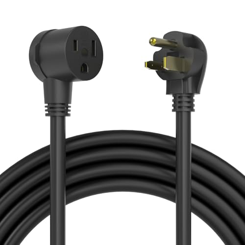
50FT CORD LENGTH: Safely extend your power up to 50 ft away, which may be combined with your existing welder cords and adapters, protecting you and others from hazardous welder spark.
Matching Plugs, Conductors, and Circuits
The connector must match the welder and the supply. A NEMA 6-50 plug is a 240-volt-class grounding configuration commonly found on some welders, but it is not a universal welding plug. Other machines use NEMA 5-15, 5-20, 6-20, 14-50, proprietary multi-voltage adapters, or hardwired input.
Conductor count matters. A straight 240-volt welder may use two ungrounded conductors and an equipment-grounding conductor. Equipment that also needs 120-volt loads may require a neutral and a four-wire connection. Never omit, repurpose, or bond a conductor to make mismatched equipment fit.
Use a dedicated branch circuit when the manual calls for one. The breaker protects the branch-circuit wiring; it is not a substitute for correct cord sizing. Receptacle, plug, cord connector, and conductors must be compatible with the circuit and machine.
- Do not use a household power strip or multi-outlet tap for a welder.
- Do not use a “cheater” adapter that removes the equipment ground.
- Do not cut off or reshape plug blades.
- Do not assume a dryer or range receptacle is compatible just because an adapter is sold for it.
- Do not connect two extension cords together to gain length.
Any new receptacle, circuit, breaker, or field-installed plug must follow the welder manual and adopted electrical code. Related circuit-planning principles are covered in this guide to 120-volt and 240-volt shop-equipment circuits.
Products Worth Considering
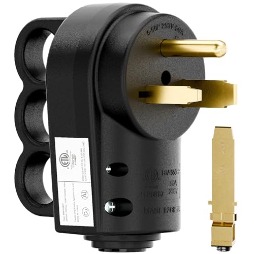
ETL Listed 2-in-1 NEMA 6-30P/6-50P straight blade welder plug, rated 30A/50A 250V for welding equipment

✅【Extremely Heavy Duty 】 30/50 Amp 250V, NEMA 6-30P NEMA 6-50P, 2 Pole 3 Wire, UL Listed. Grounding Heavy Duty Straight Blade Angle Plug.

【Universal Compatibility】This heavy-duty male plug supports NEMA 6-30P and 6-50P, functioning as both a 30 amp plug and a 50 amp plug. It's a versatile 220v plug suitable for a wide range of electrical plugs and devices
Essential Cord Markings and Safety Features
Choose a complete cord set that is marked for the required voltage, current, conductor size, number of conductors, and location. A recognized listing mark from an OSHA-recognized Nationally Recognized Testing Laboratory helps show that the product was evaluated to an applicable safety standard.
Common flexible-cord letters include:
- S: hard-service cord, generally in the 600-volt class.
- SJ: junior hard-service cord, generally in the 300-volt class.
- T: thermoplastic insulation or jacket construction.
- O or OO: oil resistance for the jacket, or for both insulation and jacket, depending on the marking.
- W: suitable for wet locations and outdoor use when the complete product is marked and used as intended.
For rough shop or outdoor service, products such as listed Type SOOW flexible cord may provide oil, water, weather, abrasion, and temperature resistance. STW and SJOOW can also be suitable in the applications covered by their markings. The correct choice depends on the actual environment and manufacturer specifications.
Reinforced or molded connectors, effective strain relief, a continuous equipment-grounding conductor, and secure contacts reduce the chance of loose connections, arcing, accidental disconnection, and heat buildup.
Choose cords made for heavy-duty portable power, not merely a light-duty indoor cord with a thick-looking jacket. A durable outer jacket can hide small conductors, so always read the printed AWG marking.
Grounding and protection remain essential throughout the setup. The same principles appear in this plasma-cutter grounding and safety checklist.
How to Connect and Use a Welding Extension Cord
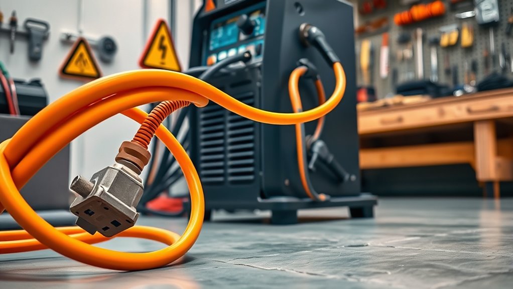
Once the cord is correctly sized and matched, use it in a way that protects the cable, connectors, circuit, and people nearby.
- Turn the welder off and inspect everything. Check the outlet, plug, connector, cord jacket, and machine power cord before connection.
- Lay out the complete cord. Fully uncoil it and route it without knots, tight bends, pinch points, or tension.
- Protect the path. Keep the cord away from sparks, hot metal, sharp edges, vehicle traffic, standing water, ladders, stairs, and walkways.
- Keep connectors clean and dry. Do not leave a plug-and-connector joint on wet ground or where metal debris can enter it.
- Make one firm connection. Insert each plug fully. Do not force mismatched blades or rely on a loose receptacle.
- Energize the circuit, then switch on the welder. Follow the machine manual’s startup sequence.
- Check during the first test weld. Stop if the plug, receptacle, connector, or cord becomes unusually warm; if you smell hot insulation; or if the machine repeatedly loses power.
- Disconnect by the plug body. Turn off the welder, de-energize when appropriate, and never pull on the cord.
OSHA requires workplace cord sets to be visually inspected before use on any shift for defects such as damaged jackets, loose parts, deformed pins, and crushed areas. The same inspection habit is sensible in a home shop. See 29 CFR 1910.334.
Pro Tip: After the first few minutes at a demanding setting, stop welding and feel the outside of the plug, connector, and cord with the power off. A slight temperature rise may occur, but a hot spot, soft plastic, odor, or discoloration means the setup needs immediate attention.
Ground-fault protection requirements vary with the location, equipment, workplace rules, and electrical-code edition adopted locally. Garages, outdoor areas, construction sites, damp locations, and conductive spaces can have added requirements. Ask a qualified electrician when the applicable protection is unclear.
Troubleshooting Welding Extension Cord Problems
Do not keep welding through an electrical symptom. Turn off the machine and inspect the entire power path before restarting.
| Symptom | Possible cause | Safe next step |
| Cord or connector feels hot | Undersized or too-long cord, coiled cable, loose contact, corrosion, damaged conductor, or overload | Stop, unplug after de-energizing, and remove the setup from service until the cause is corrected |
| Breaker trips repeatedly | Overloaded circuit, wrong supply, damaged cord, ground fault, loose connection, or machine fault | Do not increase the breaker size; compare the circuit with the manual and have the fault diagnosed |
| Arc becomes weak or erratic | Low input voltage, excessive voltage drop, poor supply connection, or a separate welding-process problem | Verify the manual, shorten or correctly upsize the cord, and inspect both input and welding-output connections |
| Plug or receptacle is discolored | Loose or worn contacts, arcing, contamination, or overheating | Stop using it; have the receptacle and connector replaced or repaired by a qualified person |
| GFCI trips | Leakage current, moisture, damaged insulation, wiring fault, or equipment fault | Do not bypass the GFCI; dry and inspect the setup, then obtain qualified service if tripping continues |
For many machines, cord problems are only one possible cause of poor performance. Check the work clamp, weld leads, polarity, consumables, settings, and joint preparation as well. Welding technique also matters; for example, oversized fillet welds can add distortion and cracking risk even when the electrical supply is correct.
Warning: A breaker that trips, a hot connector, melted plastic, buzzing receptacle, smoke, or a burning odor is not a normal operating condition. Stop using the equipment and correct the cause before welding again.
Maintenance, Storage, and Repair
Regular care helps the cord remain flexible, mechanically sound, and electrically reliable.
- Inspect the full length before each use and after any event that could crush, cut, overheat, or soak the cord.
- Keep plugs, connectors, and jackets clean and dry.
- Coil the cord in large, relaxed loops without kinks or tight bends.
- Store it away from sunlight, welding spatter, sharp edges, oil or chemicals beyond its rating, rodents, and vehicle traffic.
- Do not hang the cord from its plug or connector.
- Label the cord with its voltage, connector type, AWG, length, and intended welder so it is not mistaken for a lighter cord.
Flexible cords used in workplaces must be suitable for the conditions and location. OSHA also limits their use as a substitute for fixed wiring and requires strain relief at terminations. See 29 CFR 1910.305.
Repair or Replace?
Remove a damaged cord from service immediately. For a homeowner, replacement with a listed, correctly rated cord set is usually the safest choice. A wrap of ordinary electrical tape is not an acceptable fix for crushed conductors, exposed copper, heat damage, missing ground pins, loose connector bodies, or badly cut insulation.
Some hard-service flexible cords may be repairable under specific workplace rules when a qualified person restores the cord’s insulation, outer sheath, strain relief, and usage characteristics. That is not permission for an improvised splice. Follow the cord manufacturer, workplace program, and applicable code.
The same “use equipment only within its marked limits” rule applies throughout the shop. For example, confirm the maximum safe operating speed on an angle-grinder wheel before use.
How to Spot Wear and Tear
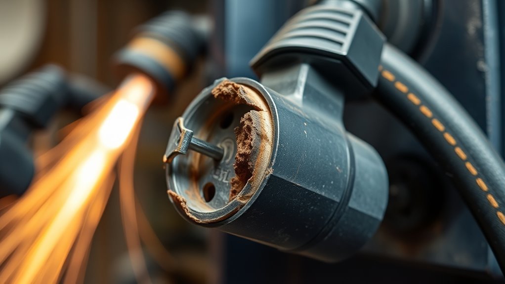
Inspect the cord while it is disconnected and de-energized. Bend it gently as you look along the jacket so cuts, flattened sections, or stiff areas are easier to see.
- Frayed, cut, or cracked insulation: Damage can expose energized conductors and create shock or fire hazards.
- Crushed, pinched, or flattened sections: Internal conductor strands may be broken even when copper is not visible.
- Bent, loose, missing, or corroded pins: Poor contact can cause arcing and localized overheating.
- Discoloration, melted plastic, bubbling, or a burnt smell: These are signs of heat damage.
- Stiff or brittle jacket material: Aging, chemical exposure, heat, or cold damage may have reduced flexibility and insulation integrity.
- Loose connector shell or failed strain relief: Pulling force may be reaching internal terminals.
- Exposed copper or damaged equipment-grounding path: Remove the cord from service immediately.
A continuity test with a multimeter is not a complete safety test and must never be performed on an energized cord. A trained person may test a disconnected cord for conductor continuity and correct terminal connections, but those checks do not prove that the insulation, contacts, ampacity, or performance under load are safe. Construction workplaces may require formal testing under an assured equipment grounding conductor program.
Use every tool and accessory only for its intended rating. In the same way, choosing the correct cut-off wheel size and method reduces overheating and tool failure.
Safety Standards for Welding Power and Cables
Home shops, commercial facilities, and construction sites can fall under different rules. OSHA standards apply to covered workplaces; residential installations are governed by the electrical code adopted by the local authority. Manufacturer instructions also remain part of a safe installation.
Extension-Cord and Temporary-Wiring Rules
OSHA’s general-industry rules require workplace extension cords to be inspected before use on a shift when they are exposed to damage. Flexible cords must be suitable for the conditions and location, used in continuous lengths except for narrowly allowed qualified repairs, and provided with strain relief.
Flexible cords are temporary connections, not a substitute for permanent building wiring. Do not run them through walls, ceilings, floors, doorways, or windows where they can be pinched or damaged; attach them to building surfaces; conceal them; or staple them in place.
Ground-fault protection and assured equipment grounding conductor requirements can apply on construction sites and in certain wet, outdoor, or conductive locations. Local electrical-code editions also change over time. The NFPA summary of 2026 NEC changes is one example of why local adoption and current requirements should be checked rather than assumed.
Welding Work Leads and Machine Grounding
The work lead is part of the welding-output circuit; it is not the same as the equipment-grounding conductor in the input cord. Attach the work clamp directly to clean metal on the workpiece or approved work fixture, as close to the weld as practical.
For covered workplaces, OSHA’s arc-welding standard requires the work-lead circuit to have adequate current-carrying capacity and mechanically strong, electrically adequate connections. Conduits containing electrical conductors, chains, wire ropes, cranes, hoists, and elevators must not carry welding current. Pipelines must not be used as a permanent part of the work-lead circuit; limited construction exceptions have specific precautions.
Keep current-carrying components properly insulated, and replace damaged welding leads when required. Do not rely on building piping, a random structure, or the equipment-grounding conductor as the normal welding-current return path.
Good equipment maintenance reduces electrical and mechanical risk across the shop. This guide to angle-grinder kickback and equipment maintenance covers related inspection habits.
Note: Electrical rules vary by jurisdiction and work setting. A qualified electrician should verify any new 120-volt or 240-volt circuit, altered receptacle, field-installed plug, uncertain grounding arrangement, repeated breaker trip, or heat-damaged outlet.
Quick Safety Checklist for Welding Extension Cords
- Manual permits extension-cord use: Confirm the manufacturer’s instructions for the exact model.
- Input data checked: Match voltage, phase, input current, duty-cycle information, and maximum permitted length.
- Correct AWG and conductor count: Read the cord marking instead of judging by color or outside diameter.
- Compatible plug and connector: Use the exact approved configuration, such as NEMA 6-50 only when the machine requires it.
- Correct jacket and listing: Match wet, outdoor, oil, abrasion, temperature, and workplace requirements.
- One continuous cord: No daisy chains, power strips, improvised adapters, or defeated ground pins.
- Fully uncoiled and safely routed: Keep it clear of hot work, traffic, sharp edges, water, and walkways.
- Inspection passed: No cuts, crushed spots, loose pins, corrosion, exposed copper, heat marks, or failed strain relief.
- Circuit is correct: Breaker, receptacle, wiring, and ground-fault protection meet the manual and local rules.
- No abnormal heat or tripping: Stop at once if any connector becomes hot or protection operates.
Use robust insulation and secure connectors to support reliable power delivery. More related information is available in the site’s power and electrical requirements resources.
Frequently Asked Questions
What are the OSHA rules on extension cords?
In covered workplaces, OSHA requires inspection before use on a shift when cords are exposed to damage, suitable cords for the location, strain relief, and removal from service when defects could create hazards. Flexible cords generally cannot replace permanent wiring or be run where they can be pinched, concealed, or damaged. Construction sites can also require GFCI protection or an assured equipment grounding conductor program.
What extension cord should you use with a welder?
Use a listed heavy-duty cord that the exact welder manual permits. Match the manufacturer’s minimum AWG, maximum length, input voltage, input current, conductor count, jacket type, plug, connector, and location rating. Do not choose from welding-output amps or a universal gauge chart.
Why can extension cords create safety problems?
Every extension adds conductor resistance and two connection points. An undersized, too-long, coiled, wet, damaged, or loosely connected cord can produce voltage drop, heat, arcing, shock risk, breaker trips, and poor welder performance. Temporary cords are also easier to crush, cut, or trip over than fixed wiring.
Can you plug a welding machine into a house outlet?
Only when the welder is designed for that exact outlet and the branch circuit meets its manual. A 120-volt welder may require a dedicated 15- or 20-amp circuit. Many larger machines require a correctly installed 240-volt circuit, breaker, receptacle, and equipment grounding path. Never force a plug or upsize a breaker to make the machine run.
How long can a welding extension cord be?
Use the shortest cord that safely reaches the work area and never exceed the manufacturer’s maximum length for the specified AWG and input voltage. A longer run increases voltage drop and may require a larger conductor. When the manual gives no extension-cord data, ask a qualified electrician rather than guessing.
Can you use a dryer or range outlet for a welder?
Only if the welder manufacturer allows that exact supply and a qualified person confirms that the receptacle, voltage, conductor arrangement, breaker, grounding, and adapter or cord set are compatible. Older three-wire dryer outlets, modern four-wire range outlets, and NEMA 6-50 welding connections are not interchangeable.
Can you make your own welder extension cord?
A field-assembled cord requires correctly rated flexible cable, compatible listed connectors, proper conductor termination, equipment grounding, strain relief, enclosure assembly, and code compliance. Incorrect assembly can create hidden shock and fire hazards. A listed preassembled cord is the safer choice for most users; otherwise, have a qualified electrician build and test it.
Can you leave a welder extension cord coiled?
No. Lay out the full cord before welding. A tightly coiled cord cannot release heat as well, and the unused length still carries current. Full uncoiling also makes damage easier to see and reduces concentrated heat, knots, and mechanical strain.
Sources
- OSHA 29 CFR 1910.334 — Use of equipment — workplace inspection and safe handling of flexible cords.
- OSHA 29 CFR 1910.305 — Wiring methods, components, and equipment — permitted uses, prohibited routing, continuous lengths, markings, and strain relief.
- OSHA 29 CFR 1910.254 — Arc welding and cutting — work-lead circuit capacity, connections, and prohibited welding-current paths.
- Miller Multimatic 200 Owner’s Manual — model-specific electrical-service and extension-cord data showing why the machine manual controls.
- Southwire Type SOOW Flexible Cord — marked service, voltage, oil, water, weather, abrasion, and temperature characteristics.
- NFPA — Key Changes in the 2026 NEC — current electrical-code changes and the need to confirm local adoption.
Conclusion
The safest welding extension cord is the one approved for your exact welder and matched to its input voltage, input current, conductor count, plug, circuit, environment, and distance. Gauge matters, but it is only one part of the decision.
Inspect the complete cord before every job, keep it fully uncoiled and protected, and stop at the first sign of abnormal heat, tripping, arcing, damaged insulation, or loose contacts. Never solve an electrical problem with a larger breaker, a makeshift adapter, or a taped-over damaged cord.
A few minutes spent checking the manual, markings, connectors, and route can prevent poor welds, equipment damage, fire, and serious electric shock.




