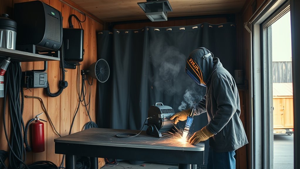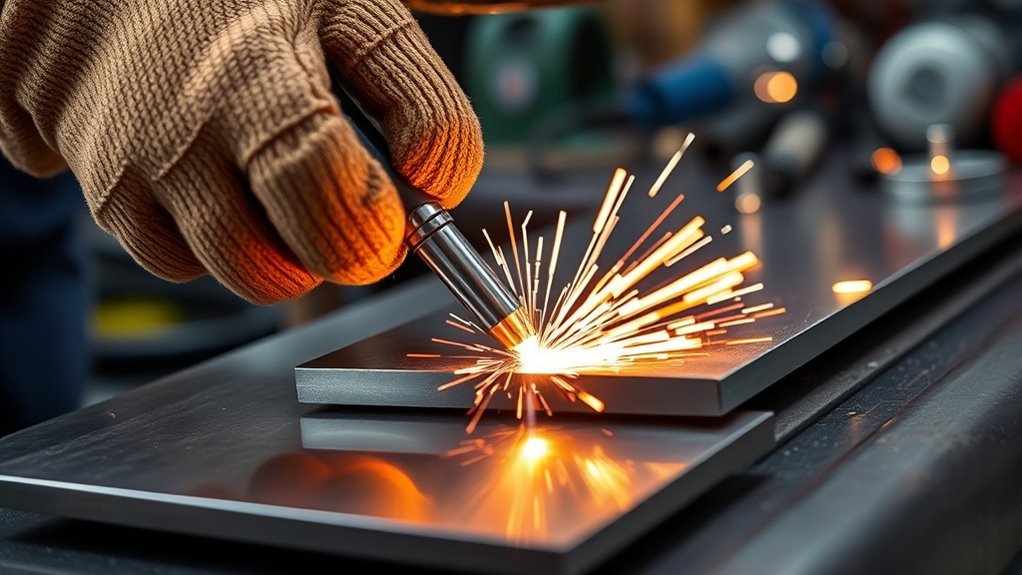
A plug weld joins two overlapping metal pieces through a round hole in the upper piece. A strong result depends on more than filling that hole with weld metal. You need clean surfaces, a procedure-approved hole size, tight contact between the pieces, suitable machine settings, and a test that confirms the weld fused to the lower sheet.
Quick Answer
To make a plug weld, clean both mating surfaces, drill the specified hole in the upper sheet, deburr it, and clamp the sheets tightly. Start the arc on the exposed lower sheet, establish a molten pool, then move outward to fuse the hole edge and fill the opening. Inspect and test a scrap coupon before final welding.
Key Takeaways
- Use the hole diameter, spacing, weld count, filler, and process specified by the drawing, welding procedure, or vehicle repair manual.
- Expose clean metal on both mating surfaces and remove burrs that could hold the sheets apart.
- Clamp close to the hole so the upper and lower sheets remain in firm contact.
- Begin on the lower sheet, then wash the weld pool into the edge of the upper hole.
- A smooth surface is not proof of fusion. Make test welds and use the acceptance method required for the job.
At a Glance
| Time Required | About 20–45 minutes for a small practice joint, including preparation, drilling, setup, welding, and inspection |
| Difficulty | Intermediate; practice on matching scrap before working on a finished or safety-critical part |
| Tools Needed | Welder, approved wire or filler, drill or hole punch, center punch, deburring tool, clamps, cleaning tools, measuring tools, PPE, and fume control |
| Cost | Variable; usually limited to wire, shielding gas, drill bits, abrasives, cleaners, and protective supplies when you already own the welding equipment |
What’s in This Article
- What You Need to Know Before Plug Welding
- Essential Tools and Safety Equipment
- Prepare the Metal Surfaces
- Choose and Drill the Plug-Weld Holes
- Clamp the Joint Securely
- Choose the Process and Settings
- Make the Plug Weld Step by Step
- Common Plug-Welding Mistakes
- Check Plug-Weld Quality
- Fix Common Plug-Welding Problems
- Finish and Protect the Joint
- Advantages and Applications
- Frequently Asked Questions
- Conclusion
- Sources
What You Need to Know About Plug Welding Before You Start
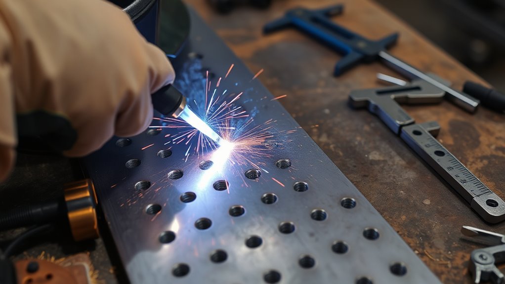
A plug weld joins overlapping members through a round hole in one member. Weld metal fills the hole and fuses with the exposed lower piece and the wall of the upper hole.
A slot weld uses an elongated opening instead of a round one. A resistance spot weld joins sheets by passing current through squeezed electrodes and normally does not require a drilled hole. Welders sometimes use the informal term “rosette weld” for a plug weld, but “plug weld” is the standard term used on welding symbols.
The correct plug diameter, pitch, quantity, filling depth, and hole location come from the drawing or repair procedure, not from one universal rule.
When a Plug Weld Is Appropriate
Plug welds are useful for lap joints when you can reach only one side of the assembly or when a specified arc-welded plug is being used in place of another approved joining method. Common examples include sheet-metal fabrication, brackets, flanges, vehicle body panels, and selected repair joints.
Do not assume that a plug weld can replace every factory spot weld or structural joint. For vehicle repairs, follow the model-specific body repair manual. High-strength and ultra-high-strength steel can have strict limits on heat, sectioning, filler wire, hole size, and approved welding locations.
Warning: Do not use general online instructions for a frame, suspension mount, seat-belt anchor, airbag-related structure, lifting point, pressure vessel, load-bearing structure, or coded weld. Use an approved procedure and a qualified welder or inspector.
Follow the Drawing, WPS, or Repair Manual
Before drilling, identify what controls the joint:
- Fabrication drawing: May show plug diameter, pitch, quantity, filling depth, and which member receives the holes.
- Welding procedure specification: May control process, base metal, filler, shielding gas, polarity, position, preheat, and acceptance.
- Vehicle repair manual: May specify weld locations, count, plug-hole diameter, approved wire, and whether plug welding is allowed at all.
- Machine manual or parameter chart: Provides safe starting settings for the selected material, wire, and thickness.
If the project also includes edge or fillet welds, follow the design requirements rather than applying a plug-weld dimension to another joint. This guide to maximum fillet weld size for plate thickness explains why weld dimensions must match the joint design.
Essential Tools for Successful Plug Welding
Gather everything before you start so the joint does not move or become contaminated while you search for a tool.
- A welder suitable for the material and approved procedure
- Correct filler wire or rod and shielding gas
- Drill press, hand drill, or approved hole punch
- Sharp drill bit in the specified diameter
- Center punch, ruler, square, and marker
- Deburring tool, file, wire brush, or suitable abrasive
- Plug-weld clamps, locking pliers, or other firm clamps
- Clean backing or heat sink when the procedure permits one
- Welding helmet, safety glasses, gloves, hearing protection, protective clothing, and closed footwear
- Local fume extraction or another ventilation system suitable for the material and work area
- Fire extinguisher and fire-control equipment appropriate for the shop
A handheld angle grinder can help prepare bare, uncoated metal when used with the correct guard, wheel, and side handle. Review this explanation of the angle grinder side handle before grinding in a confined joint area.
For a broader overview of cutting and shop protection, see this guide to personal protective equipment for plasma cutting. Always use the PPE required for the actual welding, drilling, or grinding task.
Warning: Welding can expose you to hot metal, ultraviolet radiation, electrical shock, fumes, fire, and flying particles. OSHA requires suitable eye protection and ventilation controls, and nearby people also need protection from the arc. Remove or shield combustible materials and inspect the area for smoldering material after welding.
Products Worth Considering

Purging Kit: Includes 7 pairs of purging plugs covering sizes from 0.9" to 4.0" (3.5"-4.0", 3.0"-3.5", 2.5"-3.0", 2.0"-2.5", 1.5"-2.0", 1.2"-1.5", 0.9"-1.2"). Yellow and purple pieces form standard pairs. Comes with a 5-meter heavy-duty welding hose and a durable storage case for easy carry.
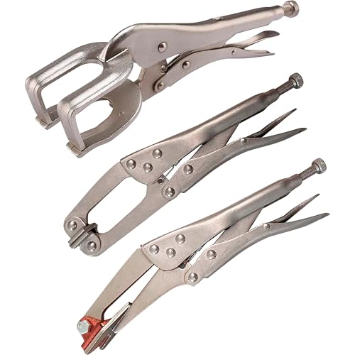
Includes 10in. plug weld plier, 10in. locking plier and 10in. claw welding clamp.

: Quick fitting makes the much easier, while the conspicuous red and black colours the working.
Prep Your Metal Surfaces Before Welding
Clean both mating surfaces, not only the visible face around the drilled hole. Rust, scale, paint, oil, sealant, adhesive, zinc, and trapped debris can interfere with fusion or create hazardous fumes.
If the coating is unknown, stop and identify it before heating or grinding it. Review the product label and safety data sheet. Do not let chlorinated-cleaner vapors enter the welding area, and allow an approved cleaner to evaporate completely before striking an arc.
When welding galvanized steel, follow the approved procedure for coating removal, ventilation, and corrosion restoration. This guide explains how to remove zinc coating from galvanized steel. Also review these MIG welding precautions for galvanized steel.
Note: The Canadian Centre for Occupational Health and Safety identifies zinc, oils, rust inhibitors, paints, solvents, and other coatings as possible sources of hazardous welding fumes. It recommends removing coatings safely and controlling residue before welding.
Clean Metal Thoroughly
Use a cleaning method that suits the contaminant and does not create a worse exposure. A wire brush or abrasive may be suitable for ordinary rust on known steel, while hazardous coatings may require controlled stripping or professional removal.
| Contaminant | Preparation | Important Precaution |
|---|---|---|
| Light rust or mill scale | Wire brush or suitable abrasive | Wear eye and respiratory protection appropriate for the dust |
| Paint or primer | Identify the coating and follow its SDS and repair procedure | Do not heat or grind an unknown or hazardous coating without controls |
| Oil or grease | Use a welding-safe cleaner approved for the material | Keep chlorinated-cleaner vapors away from welding and let the surface dry |
| Galvanized coating | Follow the approved coating-removal and repair method | Control zinc fumes and restore corrosion protection after welding |
| Weld-through primer | Apply only where the repair procedure and product instructions permit it | Excess primer can increase contamination and reduce consistency |
Clean the hole wall, the underside of the upper sheet, and the lower sheet exposed through the hole. Wipe away loose dust and chips before clamping.
Check for Proper Fit
The upper sheet must sit firmly against the lower sheet around the hole. Burrs, distorted flanges, old adhesive, weld nuggets, or trapped debris can create a gap that the weld cannot bridge reliably.
- Trial-fit the pieces: Confirm the joint is aligned before drilling or final clamping.
- Remove high spots: Deburr holes and flatten damaged flange areas without thinning the required base metal.
- Check contact: Look through the hole and around the sheet edge for visible separation.
- Clamp near the weld: Place the clamp close enough to hold the sheets together without blocking the torch.
Protect Nearby Components
Before welding on a vehicle, machine, or assembled structure, inspect both sides of the joint. Move or protect wiring, hoses, fuel lines, trim, glass, sealers, electronics, insulation, and combustible material according to the applicable service procedure.
How to Accurately Drill Holes for Plug Welding
Mark each hole on the upper workpiece and use a center punch to keep the drill from wandering. Support the sheet, keep the drill square, and use steady pressure with a sharp bit.
Choose the Correct Hole Size
Do not choose one diameter for every project. Use this order of authority:
- The engineering drawing or weld symbol
- The approved welding procedure specification
- The vehicle maker’s model-specific repair information
- A qualified engineer or welding supervisor
- For certain automotive repairs with no stated size, the current industry fallback published by I-CAR
I-CAR advises using the vehicle maker’s specified plug-weld size. When an automotive procedure gives no size, I-CAR’s general guidance uses an 8 mm or 5/16-inch hole. That fallback is not a universal rule for structural fabrication, machinery, aluminum, stainless steel, or coded work.
Hole spacing and weld quantity also come from the design. On a weld symbol, plug diameter appears to the left of the symbol, while pitch and quantity may appear in their designated positions. For collision repair, match the specified locations and number of welds rather than inventing a regular spacing.
Drill and Deburr the Holes
- Measure and mark every hole location.
- Center-punch each mark.
- Clamp the upper sheet to a backing surface before drilling.
- Drill or punch the specified diameter through the upper sheet only.
- Deburr both sides without enlarging the opening beyond tolerance.
- Remove chips and clean the hole wall.
- Recheck the diameter and location before assembly.
Pro Tip: Prepare a scrap coupon using the same upper-sheet thickness, lower-sheet thickness, coating condition, hole diameter, gap, wire, gas, and welding position as the finished joint. A test made on unrelated scrap may not reveal the same problems.
Clamping Techniques for a Secure Joint
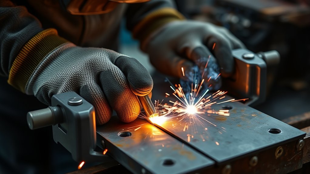
Clamping prevents movement and keeps the two sheets in contact while the weld pool forms. A gap can cause burn-through, poor tie-in, excessive filler buildup, or a weld that fills the upper hole without bonding adequately to the lower sheet.
- Use a suitable clamp: Plug-weld clamps, locking pliers, panel clamps, or a fixture can work when they provide firm contact.
- Clamp close to the hole: Place the clamp near the welding point while leaving enough room for the gun, nozzle, and visibility.
- Check the lower sheet: Confirm it cannot flex away when the wire contacts it.
- Recheck alignment: Tightening a clamp can pull thin parts out of position.
- Move clamps as needed: Do not rely on one distant clamp for a long flange.
Welding magnets can help position some assemblies, but they may not provide enough force to close a sheet-metal gap. They can also attract grinding debris. Use them as positioning aids rather than substitutes for firm joint clamping.
Choose the Welding Process and Settings
Gas metal arc welding, commonly called MIG or MAG depending on the shielding gas, is widely used for sheet-metal plug welds because the continuously fed wire fills the hole efficiently. Use another process only when the drawing, procedure, material, and your equipment permit it.
Wire, Gas, and Polarity
For light-gauge mild steel with solid wire, Miller recommends .023- or .024-inch wire as a common starting choice. The smaller wire needs less heat to melt and gives better control on thin sheet. The correct wire classification, gas, and polarity still depend on the base metal and approved procedure.
Do not assume that a mild-steel wire is suitable for high-strength steel, stainless steel, or aluminum. For stainless work, match the wire and gas to the alloy and procedure. This guide to MIG welding 304 stainless steel explains material-specific setup considerations.
Self-shielded flux-cored wire may be useful for some outdoor or thicker-steel work, but it generally adds heat and slag that make light sheet harder to control. Review these flux-core welding tips before choosing that process. When flux core is approved for the joint, use a matching flux-core settings chart and the wire manufacturer’s polarity instructions.
Set Voltage and Wire Feed
Start with the settings chart inside the welder, the machine manual, or the approved welding procedure. Material thickness, wire diameter, joint design, shielding gas, position, extension, and fit-up all affect the result.
Use this MIG welding wire-speed and voltage chart as background guidance, then confirm the setup on matching scrap.
- Too cold: The wire may pile into the hole, produce a tall crown, or fail to wash into the hole edge.
- Too hot: The lower sheet may burn through or the hole edge may melt away.
- Wire speed too high: The wire can stub into the work or drive the puddle uncontrollably.
- Wire speed too low: The arc may burn back toward the contact tip or become unstable.
Shielding Gas and Work Clamp
Protect gas-shielded welding from wind and strong ventilation drafts that disturb the gas envelope. Position fume extraction close enough to capture fumes without pulling shielding gas away from the arc.
Attach the work clamp to clean bare metal on the workpiece or an approved welding table. Keep the electrical return path secure and follow the welder manufacturer’s grounding instructions.
Executing the Plug Weld: A Step-by-Step Guide
Estimated total time: About 20–45 minutes for a small practice joint, depending on preparation, drilling, setup, cooling, and testing.
Prepare Workpieces Thoroughly
- Confirm the procedure: Verify the hole diameter, pitch, count, material, filler, and acceptance requirements.
- Clean both surfaces: Expose suitable weldable metal around the hole and on the lower sheet.
- Drill and deburr: Make the specified holes in the upper piece only.
- Fit and align: Check that the pieces sit in the required position.
- Clamp firmly: Eliminate gaps around the weld location.
- Set up the welder: Load the correct wire, confirm polarity and gas, and set starting parameters.
- Make a test coupon: Practice with matching scrap and adjust before touching the finished part.
Execute the Welding Technique Effectively
- Position the gun: Hold the wire near the center of the hole with a stable angle that gives you a clear view.
- Start on the lower sheet: Establish the arc and molten pool on the exposed lower member instead of beginning only on the upper rim.
- Confirm the pool is established: Pause long enough to melt the lower sheet without burning through it.
- Move toward the edge: Use a small circular or controlled outward motion to wash the pool into the wall of the upper hole.
- Fill the opening: Continue until the specified filling depth is reached. Many sheet-metal repair plug welds are filled level, but a drawing may specify otherwise.
- Release the trigger cleanly: Avoid leaving an unfilled crater or large central void.
- Allow cooling: Let the area cool before placing another nearby weld when distortion is a concern.
Keep the contact-tip-to-work distance consistent. Do not wave the gun far outside the hole or build weld metal only on the upper surface.
Control Heat and Weld Sequence
When several plugs are required, follow the specified sequence. On thin panels, moving between separated locations can reduce concentrated heat and distortion. Do not cool a weld with water or compressed air unless the approved procedure permits it.
If the sheet starts to pull away, buckle, or glow excessively, stop. Let it cool, inspect the fit-up, and correct the cause before continuing.
Inspect Weld Quality Diligently
After the weld cools, inspect it under good lighting. Check the diameter, fill level, edge tie-in, surrounding base metal, and visible discontinuities.
- The opening should be filled to the depth required by the drawing or repair procedure.
- The weld should tie into the full circumference of the prepared hole unless the procedure states otherwise.
- The surface should not show cracks, large pores, unfilled edges, or burn-through.
- The sheets should remain aligned and in contact.
- Spatter should not hide the edge of the weld.
Heat tint or a heat mark on the back can show that heat reached the lower sheet, but it does not prove acceptable fusion or weld strength.
Top 5 Common Plug-Welding Mistakes to Avoid
| Mistake | Likely Result | Better Approach |
|---|---|---|
| Guessing the hole size or spacing | Insufficient weld area, excessive heat, or a joint that does not match the design | Follow the drawing, WPS, or OEM repair procedure |
| Cleaning only the visible top surface | Porosity, contamination, and poor fusion to the lower sheet | Clean the underside, lower sheet, and hole wall |
| Leaving a gap between the sheets | Burn-through, excessive filler, weak tie-in, or distortion | Deburr, correct fit-up, and clamp close to the hole |
| Starting on the upper rim | A filled-looking cap with little fusion to the lower member | Establish the pool on the lower sheet first |
| Trusting appearance without a test coupon | Hidden lack of fusion or an unqualified setup | Test matching scrap and use the required acceptance method |
How to Check Your Welds for Quality
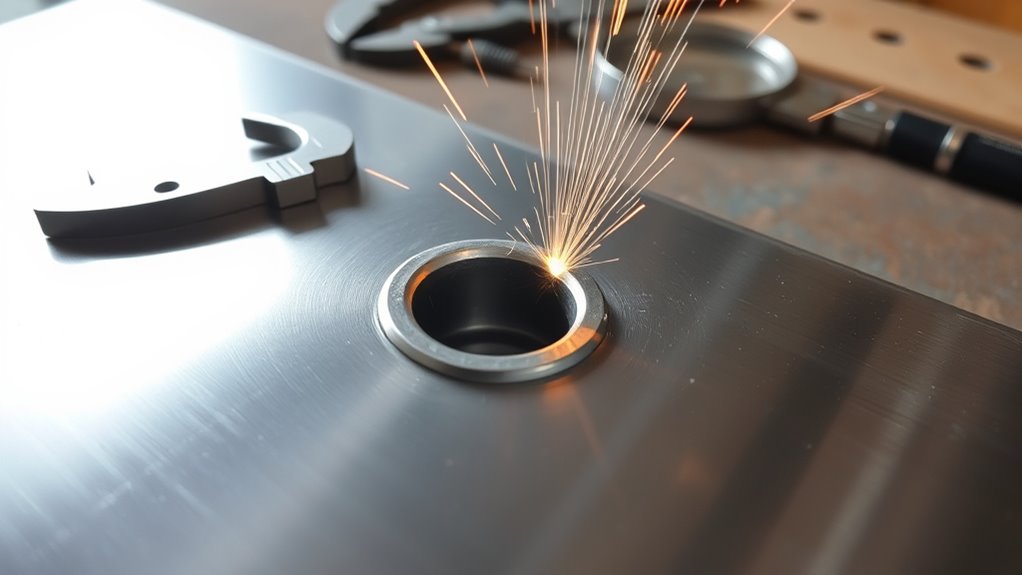
1. Perform a Visual Inspection
Visual inspection can identify surface and dimensional problems such as:
- Cracks
- Visible porosity
- Incomplete fill
- Unfused sections around the hole edge
- Burn-through
- Excessive crown or underfill
- Distortion or separated sheets
- Incorrect weld diameter or location
Measure the finished weld where the procedure gives a dimensional requirement. Clean away loose spatter before judging the edge, but do not grind away evidence before inspection.
2. Test a Scrap Coupon
A matching coupon gives you a practical way to confirm the setup before final welding. Depending on the approved procedure, the coupon may be peeled, twisted, sectioned, chisel-tested, or otherwise destructively examined to reveal whether the weld fused into the lower sheet and produced the required tear-out or nugget.
Do not improvise a destructive test on the finished part. Record the machine settings, wire, gas, hole diameter, material thickness, position, and result so you can repeat the successful setup.
3. Use Qualified Inspection When Required
Visual examination is the first inspection method, but it cannot reveal every internal discontinuity. Radiographic, ultrasonic, magnetic-particle, liquid-penetrant, and other examination methods have specific capabilities and limits.
Use formal nondestructive testing only when the applicable code, engineer, contract, or qualified inspector selects the method and acceptance criteria. A home-shop X-ray or ultrasound recommendation is not a substitute for an approved inspection plan.
Note: A neat, flat plug weld can still have incomplete fusion beneath the surface. Treat appearance as one part of inspection, not proof of strength.
How to Fix Common Plug-Welding Problems
| Problem | Likely Causes | Correction |
|---|---|---|
| Weld sits high with poor edge tie-in | Low heat, excess wire speed, long wire extension, or starting on the rim | Recheck settings on scrap, shorten extension, and establish the pool on the lower sheet |
| Burn-through | Excess heat, large gap, slow movement, oversized hole, or thin lower sheet | Correct fit-up, reduce heat as the procedure permits, and retest on matching scrap |
| Porosity or pinholes | Oil, paint, coating, moisture, poor gas coverage, wind, leak, or blocked nozzle | Remove contamination, correct gas flow and leaks, clean the nozzle, and shield the work from wind |
| Hole edge melts away | Too much heat, long dwell on the rim, irregular hole, or thin edge | Use the specified hole, begin centrally, and move into the rim only after establishing the lower pool |
| Incomplete fill | Trigger released too early, unstable arc, poor visibility, or incorrect technique | Improve access and lighting, stabilize the gun, and fill to the specified depth |
| Crack in or around the weld | Wrong filler, incompatible material, contamination, excessive restraint, or improper cooling | Stop and identify the material and governing procedure; do not simply cover the crack with more weld |
| Sheets separate during welding | Weak or distant clamp, burrs, trapped material, or heat distortion | Remove the cause, restore fit-up, and clamp closer before rewelding |
Remove a defective weld only by a method allowed for the part. Grinding, drilling, or cutting can thin the base metal and enlarge the repair area. If the defect affects a critical component, stop and have the repair evaluated by a qualified professional.
Products Worth Considering

Designed to aide and speed up the welding of holes in steel body panels

✅【Complete Pro Welding Kit: 36 Plugs in 3 Precision Sizes】:This all-in-one 38-piece professional kit is engineered for ultimate versatility. It includes 12 plugs of 0.75", 12 of 1.00", and 12 of 1.375" diameter, covering the most common hole sizes in auto and metal work. Paired with a high-speed drill bit and a strong square magnetic holder, it delivers a complete, ready-to-use solution for permanent repairs.

Post-Weld Finishing and Corrosion Protection
Let the weld cool naturally, then complete the inspection before dressing it. Do not automatically grind every plug weld flush. A proud weld may be required, and aggressive grinding can reduce the effective weld size or thin the surrounding sheet.
When the procedure allows flush finishing:
- Use a controlled abrasive and light pressure.
- Stop as soon as the required profile is reached.
- Do not grind into the surrounding base metal.
- Reinspect for pores, cracks, edge defects, and underfill.
- Clean the area before applying corrosion protection.
Restore primer, seam sealer, cavity wax, paint, galvanic isolation, or another protective system according to the material and repair procedure. Welding and coating removal expose bare metal that can corrode if left untreated.
Advantages of Plug Welding in Various Applications
When the joint is properly designed and welded, plug welding offers several practical benefits:
- One-sided access: You can join an overlapping member through prepared holes when the back side is difficult to reach with another arc-welded joint.
- Repeatability: A fixture, controlled hole pattern, and documented setup can produce consistent joints.
- Sheet-metal suitability: GMAW plug welds are widely used in selected panel and flange applications.
- Limited external bead length: The weld is concentrated inside a defined opening instead of running along the entire lap edge.
- Flexible materials and processes: Plug welds can be used on suitable steels, stainless steels, and some aluminum applications when the correct procedure, filler, shielding, and preparation are used.
These advantages do not remove the need for engineering requirements. Joint strength depends on material properties, hole diameter, pitch, quantity, filler, fusion, loading direction, edge distance, and the surrounding structure.
Frequently Asked Questions
What Types of Metals Are Best for Plug Welding?
Mild steel is common because it is widely compatible with GMAW sheet-metal procedures. Stainless steel and some aluminum alloys can also be plug welded, but they need material-specific filler, shielding, preparation, and settings. Never assume the same procedure works for every alloy or high-strength steel.
Can I Plug Weld on Painted Surfaces?
Do not weld directly through ordinary paint. Identify the coating, follow its safety data sheet, and expose suitable metal where the weld must fuse. A procedure may permit a specific weld-through primer between flanges, but you should apply only the approved product and amount.
How Do I Prevent Warping During Plug Welding?
Use tight fit-up, the correct hole size, suitable settings, and the specified weld sequence. When the procedure allows it, alternate between separated weld locations and let the panel cool between nearby plugs. Avoid unnecessary heat, overwelding, and unapproved rapid cooling.
What Is the Ideal Plug-Weld Hole Size?
There is no universal ideal diameter. Use the engineering drawing, welding procedure, or OEM body repair manual. For certain automotive work with no stated size, I-CAR publishes an 8 mm or 5/16-inch fallback, but that guidance should not be applied automatically to unrelated fabrication.
Is Plug Welding Suitable for Outdoor Projects?
It can be, but wind can remove shielding gas and cause porosity. Keep the metal dry and clean, shield a gas-protected arc from wind, and use only a process permitted by the procedure. Never weld in rain or while standing on wet ground with unsuitable equipment.
How Do I Know If a Plug Weld Failed?
Warning signs include cracking, incomplete fill, porosity, burn-through, unfused hole edges, separated sheets, or failure during a procedure-approved coupon test. A clean surface alone does not prove acceptance. Critical joints need the inspection required by their code or repair procedure.
Can a Plug Weld Replace a Spot Weld?
Only when the engineering or repair procedure allows the substitution. Vehicle makers may require resistance spot welding in some locations and permit MIG or MAG plug welds in others. Match the specified weld locations, number, hole diameter, wire, and testing requirements.
Should I Grind a Plug Weld Flush?
Grind it flush only when the drawing or repair procedure permits it. Inspect the weld first, use light pressure, and avoid removing required weld metal or thinning the surrounding sheet. Structural plug welds may need to remain undressed.
Safety Disclaimer: This article is for informational purposes only and does not replace hands-on training, an approved welding procedure, engineering requirements, a vehicle body repair manual, workplace rules, or advice from a qualified welding professional. Always follow your equipment manual and applicable safety standards.
Conclusion
A proper plug weld begins with the procedure, not the welding gun. Confirm the required hole diameter, spacing, weld count, filler, process, and acceptance criteria before drilling. Then clean both surfaces, deburr the hole, clamp the sheets tightly, and prove the setup on matching scrap.
During welding, establish the pool on the lower sheet before tying into the upper hole edge. Afterward, inspect the weld and use the required coupon test or qualified inspection method. Finish by restoring any coating, sealer, paint, or corrosion protection removed during the work.
Sources
- MillerWelds: How to Read and Understand Weld Symbols — plug- and slot-weld definitions, diameter, pitch, quantity, and filling-depth notation
- I-CAR: Steel Spot and Plug Weld Nugget Size — automotive procedure priority and general fallback hole-size guidance
- MillerWelds: Successfully Welding Sheet Metal With MIG and TIG — light-gauge wire and heat-control guidance
- OSHA 29 CFR 1910.252 — eye protection, ventilation, zinc, coatings, and cleaning-compound requirements
- CCOHS: Welding Fumes and Gases — hazardous fumes from zinc, coatings, oils, paints, and solvents
- CCOHS: Welding Ventilation — local exhaust and welding-fume control