
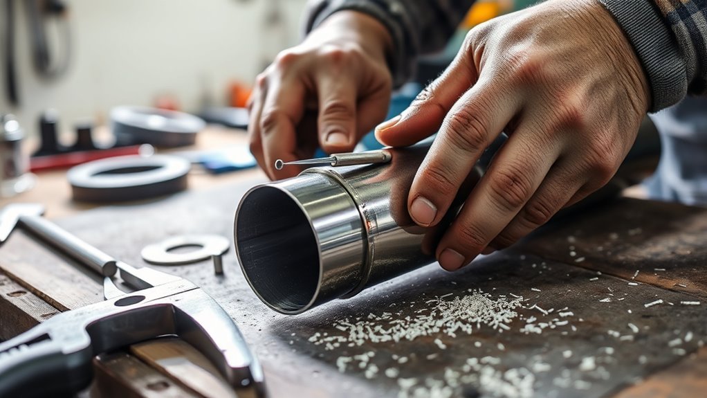
Making pie cuts for custom exhaust tubing requires more than choosing an angle and feeding the tube through a saw. You need to plan the completed bend, distinguish the saw’s miter angle from the direction change at each joint, keep every segment clocked correctly, and control movement while tacking and welding. A scrap test piece can prevent an entire tube from being cut to the wrong geometry.
Last updated: July 20, 2026.
Quick Answer
Plan the total bend and number of joints first. Divide the bend angle by the number of joints to find each joint’s direction change, then halve that value for equal miter cuts on both mating ends. Verify the saw with scrap, use a fixed stop, deburr, align witness marks, tack the complete bend, and finish-weld only after test-fitting.
Key Takeaways
- Do not confuse the completed joint angle with the miter angle set on the saw.
- Use a longitudinal clocking line, numbered pieces, and a secure backstop to keep the bend repeatable.
- Choose blade pitch for the tube wall and material rather than relying on one tooth count for every job.
- Deburr and clean every edge, assemble the entire bend, and tack it before making any final welds.
- Check clearances, support, leaks, noise, and emissions legality before driving the vehicle.
At a Glance
| Time Required | About 1 to 3 hours for planning, cutting, deburring, and test-fitting; welding and installation take additional time |
| Difficulty | Intermediate metal fabrication and thin-wall welding |
| Tools Needed | Metal-cutting band saw or cold saw, angle gauge, ruler, pipe wrap or masking tape, marker, clamps, stop block, files or deburring tools, grinder, welder, and suitable PPE |
| Cost | Varies with tubing material, blade wear, abrasives, shielding gas, filler metal, clamps, and other consumables |
Plan the Bend and Calculate the Cut Angle
Start with the shape you need under the vehicle rather than with an arbitrary saw setting. Use a full-size cardboard template, a piece of stiff wire, a drawing, or a CAD model to record the total direction change and the space available for the bend. Check the proposed path against the floor, frame, suspension, driveshaft, steering, fuel and brake lines, heat shields, bumper, and bodywork.
Four terms must remain separate:
- Total bend angle: The complete change in direction, such as 45 or 90 degrees.
- Weld joint: One connection between two mating tube sections.
- Joint deflection: The direction change created by that completed joint.
- Miter angle: The angle cut on each tube end, measured from a square cut when both mating ends share the angle equally.
For equal joints and equal miters on both mating ends, use these formulas:
Joint deflection = total bend angle ÷ number of equal joints
Miter angle on each mating end = joint deflection ÷ 2
Miter angle = total bend angle ÷ (2 × number of equal joints)
| Total Bend | Equal Joints | Direction Change per Joint | Equal Miter on Each End |
|---|---|---|---|
| 90 degrees | 6 | 15 degrees | 7.5 degrees from square |
| 90 degrees | 12 | 7.5 degrees | 3.75 degrees from square |
| 45 degrees | 6 | 7.5 degrees | 3.75 degrees from square |
Note: Saw scales are not all labeled the same way. Some display degrees away from a square cut, while others use a different zero reference. Confirm the blade with a digital angle gauge or a scrap coupon before cutting production pieces.
The short-side length of each segment controls the bend’s approximate radius. At the same angle, shorter pieces form a tighter bend and longer pieces form a broader bend. Tube outside diameter, wall thickness, blade kerf, weld gap, and the way you count end pieces also affect the final result. Do not copy a 30 or 38 millimeter dimension unless it matches your drawing or a verified scrap mock-up.
Step-By-Step Guide to Making Pie Cuts
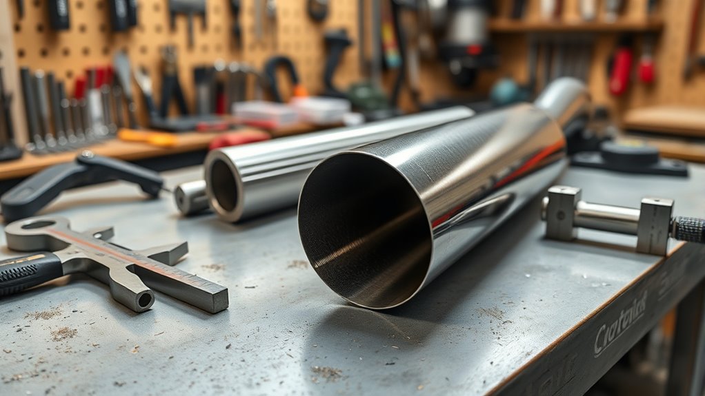
To make precise pie cuts, begin with straight, round tubing that matches the intended exhaust diameter and material. Inspect it for dents, flattened areas, heavy burrs, rust, coatings, oil, and shipping damage. A distorted tube will not sit consistently in the saw vise or produce matching joints.
1. Clean and Inspect the Tube
Remove oil and dirt with a cleaner that is compatible with the tubing and welding process. Mechanically remove coatings, scale, and oxidation from the future weld zones. Clean metal reduces layout errors and helps prevent contamination and porosity during welding. The preparation principles in this guide to welding thin metal with flux core also apply when preparing thin-wall exhaust tubing.
Avoid using galvanized tubing for a fabricated exhaust unless the material and coating are specifically intended for that service and you have a safe procedure for coating removal and fumes. Review the hazards and preparation requirements before welding galvanized steel.
2. Mark a Longitudinal Clocking Line
Draw one straight line along the tube’s length. This is the clocking or witness line. It gives every segment a common rotational reference and prevents the finished bend from slowly twisting into a corkscrew shape.
Use a straightedge, angle extrusion, tube-marking jig, or carefully stretched tape to extend the line. Mark a second reference line 180 degrees opposite the first when practical. A pipe wrap or a square-edged strip of masking tape can help establish a circumferential reference line.
3. Set the Saw and Make a Test Coupon
Set the saw to the calculated miter angle, not merely the desired direction change at the completed joint. Clamp a short scrap piece of the same tube and make two mating cuts. Deburr the pieces, rotate them into assembly position, and measure the resulting joint angle.
If two 7.5-degree miters do not produce approximately a 15-degree direction change, check the saw’s zero reference, blade drift, vise alignment, and measurement method before continuing.
4. Establish the Segment Length
Measure each segment from the same reference side, normally the short side or long side specified by your drawing. Do not alternate measurement sides. Mark the first production piece and confirm its short-side and long-side dimensions after accounting for blade kerf.
Set a rigid backstop only after the first piece matches the planned dimensions. The stop must not enter the blade path, shift under cutting force, or trap the offcut in a way that creates a pinch hazard.
5. Make Repeatable Alternating Cuts
Clamp the tube firmly so it cannot roll. Align the witness line with the same reference on the vise for every cut. Depending on your saw and cutting plan, you may alternate the tube orientation or rotate the cut piece to create mating faces. Follow the sequence established with the scrap coupon rather than improvising after each cut.
Label the pieces in order as P1, P2, P3, and so on. Add a small mark to the long side of each piece. These labels make it easier to restore the intended order if the stack is disturbed.
6. Deburr and Check Each Piece
Remove internal and external burrs without rounding away the mating edge. Check each segment against the first accepted piece. Reject or rework pieces with visible blade drift, excessive taper, dents, or a length difference large enough to open a weld gap.
7. Assemble and Tack the Bend
Arrange all pieces on a flat surface, align the witness marks, and verify the total bend angle. Use a straightedge, fixture, magnets designed for welding, or temporary clamps to hold the assembly. Tack every joint before fully welding any one seam.
Warning: Cutting and welding exhaust tubing exposes you to sharp metal, moving blades, sparks, hot surfaces, ultraviolet radiation, fumes, and fire hazards. Use the machine guards, eye and hearing protection, process-appropriate welding PPE, ventilation, and fire controls required by the tool manuals and your working conditions. Never work beneath a vehicle supported only by a jack.
Essential Tools for Making Accurate Pie Cuts
A metal-cutting band saw is a practical choice because it can hold the tube securely and repeat the same miter angle. A cold saw can also produce accurate cuts. A chop saw or abrasive saw may work, but kerf width, heat, sparks, wheel wear, and less precise clamping can make repeated thin-wall cuts harder to control.
The quality of a pie-cut bend depends on repeatability. A small difference in one piece may look harmless, but the errors add together across the complete bend.
You will also need:
- A digital angle gauge, protractor, or machinist’s square for checking the saw
- A ruler, tape measure, or caliper for consistent segment dimensions
- A pipe wrap, masking tape, straightedge, and permanent marker
- A rigid stop block or saw backstop
- Clamps or a fixture that prevent the tube from rolling
- A half-round file, deburring tool, flap disc, or small grinder
- A welding machine, correct filler, shielding gas, and suitable torch or gun
- Eye, hearing, face, body, respiratory, and fire protection appropriate to the task
Any grinding or cutting disc must be approved for the tool and have a speed rating at least as high as the grinder’s no-load speed. Review the angle grinder disc and safety guidance before using a grinder to clean or finish the joints.
Products Worth Considering
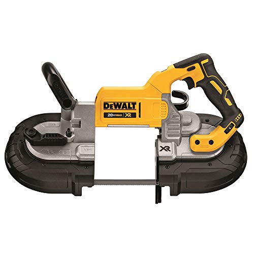

2.8-amp motor rotates the blade up to 2500 feet per minute

Huge Cutting Capacity: The cutting capacity of the band saw: without base: 4.7"x4.7" deep-cut capacity for rectangular stock, 5" capacity for round stock. With base: 3.9"x3.2" deep-cut for rectangular stock, 3.93" for round stock.
How to Mark Your Tube for Precision Cuts
Good marking establishes both length and rotation. Use a pipe wrap or a square-edged band of masking tape when you need a line around the tube. Keep the tape edge flat and even rather than spiraling it around the tubing.
Draw a longitudinal center or clocking line along the tube and carry it onto every segment. This line is more important than a decorative center mark because it controls the plane of the completed bend.
Add four types of marks:
- Clocking mark: Shows the tube’s rotational position.
- Cut mark: Shows where the blade should enter.
- Long-side mark: Identifies the outside of the bend.
- Sequence number: Preserves the planned assembly order.
Before clamping, check the first and last marks against the drawing. If the layout must change direction in more than one plane, record the intended rotation at each joint rather than turning pieces by eye.
Pro Tip: Put a small witness mark on the long side of every pie cut and photograph the dry assembly before moving it. If the pieces get mixed up, the labels and photo make the original bend much easier to restore.
Getting Your Bandsaw Ready to Work
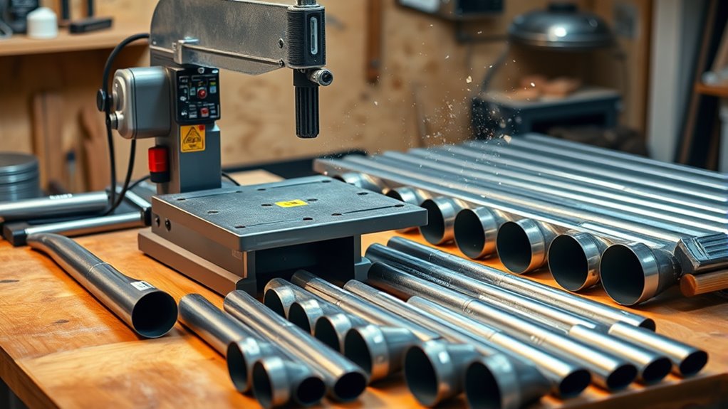
Inspect the bandsaw before cutting. Confirm that the blade is sharp, correctly tensioned, seated in the guides, and suitable for the tube material. Check that guards are installed and that the vise closes squarely without allowing the round tube to roll.
Choose tooth pitch according to the tube wall and the blade manufacturer’s chart. As a general sawing rule, keep at least three teeth and no more than about 10 to 14 teeth engaged in the material at one time. Thin-wall tubing normally needs a finer pitch than thick solid stock. See Starrett’s band saw tooth-selection guidance for the reasoning behind this range.
Use the cutting speed and coolant or lubricant recommended for the blade and tubing. Stainless steel generally needs more careful speed, feed, and heat control than mild steel. Do not force the blade. Excessive feed can cause drift, damaged teeth, a rough surface, or a cut that is no longer square across the tube.
Set the jaw or material stop using the verified production piece. A dimension such as 38 millimeters is only an example and should not be treated as a standard. Your setting must come from the planned short-side or long-side segment length.
A fixed stop saves time only after the angle, kerf, and first segment have been verified. A precisely repeated wrong setup still produces a wrong bend.
If the blade pulls sideways, leaves a washboard finish, or produces unequal pieces, stop and inspect blade sharpness, pitch, tension, guides, vise alignment, feed pressure, and cutting speed. Do not compensate for mechanical drift by changing every layout mark.
Keep your welding equipment ready for the later fit-up stage, but establish its settings with scrap of the same material and wall thickness. A welding settings reference can provide a starting point, but the tubing, wire, polarity, shielding, joint gap, and machine must determine the final setting.
Products Worth Considering

Bi-metal type, M42 grade, 93" long, 3/4" wide, 0.035" thick, 10-14 TPI

INCLUDES: (1) 80 inch band saw blade for Sears Craftsman 137.224320 and other 12" band saw – suitable for most 80” long, 1/2” wide, 0. 025” thick band saw blades
Choosing the Right Angle for Pie Cuts
The correct angle depends on the available space, desired bend radius, number of welds, tube diameter, segment length, and your ability to fit and weld thin material. Smaller joint deflections create a smoother-looking polygon with more welds. Larger deflections reduce the number of joints but create a more obvious change in direction at each seam.
Thin-wall exhaust fabrication also demands careful heat control. The preparation and tack-welding principles used when welding automotive sheet metal are useful because both jobs can distort or burn through when heat input is excessive.
Common Angle Options
Describe each option by both its saw miter and the resulting equal-miter joint deflection:
- 3.75-degree miter on each mating end: Produces about a 7.5-degree direction change at the joint. It creates a gradual bend but requires more joints.
- 5-degree miter on each mating end: Produces about a 10-degree direction change. It balances smoothness and weld count.
- 7.5-degree miter on each mating end: Produces about a 15-degree direction change. Six equal joints produce approximately a 90-degree bend.
- 15-degree miter on each mating end: Produces about a 30-degree direction change. This uses fewer joints but creates a more abrupt path.
- 22.5-degree miter on each mating end: Produces about a 45-degree direction change. This is normally closer to a conventional mitered elbow than a smooth multi-piece pie-cut bend.
- Mixed angles and rotations: Useful for compound routing, but every change should be recorded in a drawing or fixture.
These are geometric examples, not mandatory exhaust settings. Verify the completed joint angle with scrap before deciding how many pieces to cut.
Impact on Flow
Pie cuts let you control routing where a ready-made elbow will not fit. They do not automatically improve exhaust flow or engine output. A properly sized mandrel bend may provide a smooth path with fewer weld seams, while a well-made pie-cut bend may provide better packaging in a restricted space.
| Joint Deflection | Fabrication Effect | Main Tradeoff |
|---|---|---|
| 7.5 degrees | Gradual change between pieces | More joints, fitting, and welding |
| 10 degrees | Moderate segment count | Requires accurate saw verification |
| 15 degrees | Fewer segments for the same total bend | More visible directional change per seam |
| 30 degrees or more | Very low joint count | Abrupt geometry and harder fit-up |
Fit-up quality matters as much as the nominal angle. Misaligned tube bores, large internal weld penetration, incomplete fusion, leaks, and steps between pieces can compromise an otherwise attractive bend. Any power change depends on the entire exhaust system, engine configuration, pipe diameter, catalytic converters, mufflers, resonators, and calibration.
Material Considerations
Choose tubing before finalizing the cutting and welding process. Stainless steel is valued for corrosion resistance, while mild or aluminized steel can be easier on the budget. The exact corrosion resistance, weldability, heat behavior, and appearance vary by grade and coating.
- Wall thickness: Thin material is light but easier to distort or burn through.
- Tube diameter: Larger tubing requires more careful support and fit-up.
- Corrosion exposure: Road salt, moisture, and condensation can shorten the life of unprotected mild steel.
- Welding process: Match the filler metal and shielding gas to the tubing.
- Service temperature: Sections close to a turbocharger, manifold, or catalytic converter experience more heat than tailpipe sections.
- Appearance: A decorative weld pattern should never take priority over fusion, sealing, clearance, and durability.
Note: More pie cuts mean more welds. Additional seams increase fitting time, heat input, distortion risk, and potential leak points. Use only as many joints as the required shape and finish justify.
How to Make the Initial Cut
Clamp the tube so it cannot roll, and keep the longitudinal witness line visible. Set the verified miter angle and make a scrap cut that creates a clean reference end. Stop the saw completely before reaching near the blade or removing the offcut.
Inspect the cut face. It should be reasonably flat, free from heavy tooth marks, and consistent around the tube wall. A poor first cut should trigger a setup correction rather than becoming the reference for every later piece.
Essential Cutting Techniques
- Confirm the blade angle with a gauge or accepted test coupon.
- Clamp the round tube against surfaces that prevent rolling.
- Keep the same clocking line against the same vise reference.
- Measure every piece from the same short or long side.
- Use steady feed pressure and allow the blade to cut.
- Check the stop after any impact, vibration, or unexpected length change.
- Number each piece as it comes off the saw.
Ensuring Accurate Measurements
Measure the first accepted segment with a caliper or steel rule and record both its short-side and long-side lengths. Those two measurements can reveal an angle or setup problem that a single length measurement misses.
Do not assume that the marked stop dimension equals the finished segment length. Blade kerf removes material, and the reference point can change when the tube is flipped or rotated. Make one complete cut cycle on scrap and measure the result before locking the process.
The earlier 38-millimeter jaw setting is best treated as a sample workshop measurement, not a universal specification. Use it only when a drawing or verified mock-up calls for that dimension.
Safety Precautions During Cutting
- Wear safety glasses with side protection and suitable hearing protection.
- Keep guards installed and adjusted according to the saw manual.
- Secure long tubing so its weight cannot tip, swing, or pull it from the vise.
- Tie back long hair and remove loose clothing, jewelry, and hanging drawstrings.
- Keep hands, measuring tools, and stop blocks out of the moving blade path.
- Use a brush or tool rather than your fingers to clear sharp chips.
- Handle sharp offcuts carefully after the blade stops. Follow the machine manual regarding glove use around moving parts.
- Disconnect power or remove the battery before changing blades, adjusting guides, or servicing the saw.
OSHA explains that moving machine parts can cause crushing, amputation, burns, and eye injuries, and that hazardous machine functions must be guarded. Review its machine-guarding guidance along with the instructions for your specific saw.
How to Ensure Consistent Cut Lengths
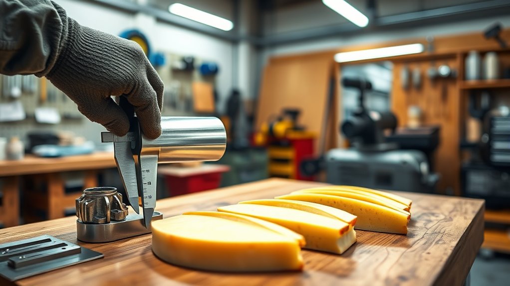
Consistent length begins with a verified first piece. Measure that piece, check its angle, and use it as the master. Set a secure backstop so the same tube reference contacts the same point before each cut.
Recheck production pieces at regular intervals rather than waiting until the full batch is complete. Compare the following:
- Short-side length
- Long-side length
- Cut-face angle
- Tube roundness
- Witness-line orientation
- Surface finish and blade drift
If dimensions begin to change, inspect the stop, blade, guides, vise, feed pressure, and tube support. A stop that shifts by a small amount can create a large cumulative error across several joints.
A plasma cutter is generally less convenient than a saw for repeated thin-wall pie segments because it introduces a wider heat-affected area and requires more edge finishing. When plasma cutting thin material for another part of the project, controlled heat and appropriate travel speed help limit distortion.
Top Mistakes to Avoid When Cutting Exhaust Tubing
- Using the joint angle as the saw angle: Equal mating miters normally use half the desired joint deflection.
- Trusting the saw scale without testing: Scale references and calibration can differ.
- Copying an arbitrary segment length: The required length depends on the tube and bend plan.
- Skipping the clocking line: Small rotational errors create a twisted bend.
- Measuring from alternating sides: This produces inconsistent segments.
- Using a loose stop: Vibration can change the length during a batch.
- Forcing a dull or unsuitable blade: This increases drift and roughness.
- Leaving internal burrs: Burrs prevent flush fit-up and may protrude into the flow path.
- Fully welding one joint too early: Heat can pull the remaining pieces out of alignment.
- Ignoring support and clearance: A bend that fits on the bench may contact the vehicle after installation.
Troubleshoot welding equipment before using the fabricated section as a test piece. Problems such as unstable output, poor grounding, inconsistent wire feeding, or incorrect polarity should be resolved using the checks in this guide to welding machine problems and solutions.
Deburring and Test-Fitting the Pie Cuts
Deburr each segment before assembly. Use a deburring tool, half-round file, cartridge roll, flap disc, or small grinder to remove sharp edges from the inside and outside. Preserve the flat mating surface and avoid creating a rounded edge that opens the joint.
Clean abrasive residue, oil, marker contamination near the weld, and loose metal particles. Hold two pieces together against a light source. A thin, even joint line is easier to control than a large or irregular gap.
Arrange the pieces on a flat surface and align the longitudinal marks. Check the total angle after every few joints. If the bend rises away from the surface or the witness line spirals, correct the rotation before tacking.
Place several small tack welds around each joint rather than relying on a single tack. Alternate tack locations to balance shrinkage. Complete the dry assembly and test it under the vehicle before finish welding.
Assembling Your Custom Exhaust System
Select the tube diameter, wall thickness, and material to suit the vehicle and the rest of the exhaust. Pie cuts provide detailed control in tight areas, but a ready-made mandrel bend may be faster and involve fewer seams when space allows.
Position the fabricated bend with enough room for:
- Engine and drivetrain movement
- Thermal expansion
- Suspension and steering travel
- Driveshaft and axle movement
- Fuel, brake, electrical, and hydraulic lines
- Heat shields, body panels, and underbody insulation
- Ground clearance and lifting points
- Hangers and removable service connections
Use clamps only at connections intended to remain serviceable. Pie-cut seams normally require complete, material-compatible welds. Before welding, review these flux-core welding preparation tips if that process is being considered, and confirm that the selected wire and process are appropriate for the tubing.
Exhaust pie cuts form butt joints rather than structural fillet joints. Guidance on maximum fillet weld size applies to different joint geometry and should not be used to size these seams.
Welding the Pie-Cut Bend
Choose a welding process, filler metal, shielding gas, polarity, and settings that match the tube material and wall thickness. TIG welding offers detailed puddle control for thin stainless tubing, while correctly configured MIG welding can be productive on suitable mild or stainless tubing. Practice on offcuts from the same tube before welding the finished bend.
Use this sequence:
- Clean every joint immediately before welding.
- Align the complete bend in a fixture or on a flat surface.
- Place multiple small tacks around every seam.
- Recheck the total angle, plane, length, and vehicle fit.
- Weld short sections in a staggered pattern rather than completing adjacent seams consecutively.
- Allow cooling periods when necessary to limit distortion and burn-through.
- Inspect each seam for missed areas, pinholes, undercut, excessive reinforcement, and internal intrusion.
When welding stainless tubing, the backside of the weld may require inert-gas purging to prevent heavy root oxidation or “sugaring.” Purging requirements depend on the grade, process, expected service, and required weld quality. ESAB explains the role of purge gas in protecting the backside of stainless pipe welds.
Warning: Welding fumes, shielding gases, sparks, and hot metal can cause serious injury, fire, or oxygen displacement. Provide suitable ventilation, remove flammable material, keep fire-control equipment nearby, and follow the welding-machine, gas-cylinder, and consumable manufacturers’ instructions.
Leak Testing and Final Installation Checks
Inspect and leak-test the fabricated section before final installation. Seal one end where practical, introduce only low regulated air pressure, and apply a soap-and-water solution to the seams. Bubbles indicate a leak. Do not use high pressure, oxygen, fuel gas, or an unregulated compressed-air source.
You can also perform a smoke test with equipment designed for automotive leak detection. Repair pinholes only after the section is depressurized, cleaned, and made safe for welding.
After installation:
- Verify that hangers support the system without forcing the bend out of alignment.
- Confirm that the exhaust cannot strike the body, axle, suspension, or driveshaft.
- Check that heat-sensitive parts have suitable clearance and shielding.
- Start the engine in a ventilated area and listen for leaks or rattles.
- Inspect the system again after the first complete heat cycle.
- Recheck clamps, flanges, hangers, and clearances after a short drive.
Warning: In the United States, do not remove, bypass, or render catalytic converters, oxygen sensors, or other emissions-control equipment inoperative on a street-driven vehicle. Other countries, states, provinces, and municipalities may impose additional emissions and noise rules. Confirm the requirements that apply where the vehicle is registered and operated.
Troubleshooting Pie-Cut Problems
| Problem | Likely Cause | Correction |
|---|---|---|
| Completed bend angle is too large | Joint deflection was used as the miter setting | Recalculate the equal miter as half the desired joint deflection and verify with scrap |
| Pieces vary in length | Loose stop, alternating reference sides, kerf error, or poor clamping | Reset the stop, use one reference side, and verify the first production piece |
| Cut face is curved or angled sideways | Blade drift, dull teeth, loose guides, excessive feed, or tube movement | Service the blade and guides, reduce feed, and improve clamping |
| Bend twists out of plane | Clocking marks were inconsistent or pieces rotated during tacking | Realign the witness marks and use a flat fixture or jig |
| Large weld gaps | Burrs, rounded edges, incorrect angles, or mismatched pieces | Deburr carefully, check the angle, and replace pieces that cannot fit evenly |
| Tube distorts during welding | Too few tacks, excessive heat, long continuous welds, or poor fixturing | Add balanced tacks, stagger short welds, reduce heat input, and allow cooling |
| Pinholes or exhaust leaks | Contamination, missed areas, unstable shielding, or poor fusion | Clean the joint, correct shielding and settings, repair, and repeat the leak test |
Frequently Asked Questions
What type of tubing material is best for exhaust systems?
Stainless steel provides strong corrosion resistance and is common in long-lasting custom systems. Mild or aluminized steel can cost less and may be easier to source, but it generally needs more protection from corrosion. Choose the grade, diameter, wall thickness, filler, and shielding gas as one compatible system.
How can I avoid warping during cutting and welding?
During cutting, use a sharp correctly pitched blade, secure clamping, steady feed, and the recommended speed. During welding, use several balanced tacks, a fixture, short staggered welds, controlled heat input, and cooling periods. Most serious distortion occurs during welding rather than from a correctly operated metal-cutting saw.
Is it necessary to deburr the cuts afterward?
Yes. Internal and external burrs can keep the pieces from sitting flush, create uneven weld gaps, injure your hands, and protrude into the tube. Remove the burr without rounding away the flat mating surface.
Can I use a different saw for pie cuts?
Yes. A cold saw, properly equipped chop saw, or abrasive saw can make pie cuts, but the machine must hold the round tube securely and repeat the angle and length. A metal-cutting band saw is often convenient because its vise, controlled feed, and stop can make repeated cuts easier.
How do I calculate the correct angle for a specific bend?
Divide the total bend angle by the number of equal weld joints to find the direction change at each joint. When both mating ends share the angle equally, divide that joint angle by two to find each miter from square. For a 90-degree bend with six equal joints, each joint changes direction by 15 degrees and each mating end is cut 7.5 degrees from square.
Does a 7.5-degree saw setting make a 7.5-degree bend?
Not when two mating ends are each cut 7.5 degrees from square. Together, those equal miters create about a 15-degree direction change at the joint. Saw scales vary, so confirm the result with two scrap pieces before cutting the full batch.
Should I tack weld or fully weld each pie cut as I go?
Tack the complete bend first. Multiple balanced tacks let you check the angle, plane, length, and vehicle clearance before heat locks the pieces in place. Once the whole section fits, finish-weld it in a staggered sequence to limit distortion.
Are pie-cut bends better than mandrel bends?
Neither option is always better. A mandrel bend normally uses fewer seams and provides a continuous curve. Pie cuts give you more control when routing through a tight or unusual space. The better choice is the one that provides suitable diameter, clearance, internal smoothness, sealing, durability, and legal compliance.
How should I test the finished bend for leaks?
Use a purpose-built automotive smoke tester or apply low regulated air pressure to the sealed section and brush soap solution over the welds. Bubbles show the leak location. Never use oxygen, fuel gas, high pressure, or an unregulated air source.
Conclusion
Accurate pie cuts begin with correct geometry. Plan the total bend, count the equal weld joints, halve each joint deflection to find equal mating miters, and confirm the saw setting with scrap. From there, consistent clocking marks, a rigid stop, clean edges, balanced tacks, controlled welding, and a final leak test will produce a bend that fits more predictably and lasts longer.
Do not let appearance replace function. The completed exhaust must remain supported, leak-free, clear of moving and heat-sensitive parts, and compliant with the emissions and noise rules that apply to the vehicle.
Sources
- OSHA Machine Guarding — supports guarding and contact-hazard precautions around powered saws and moving machinery.
- OSHA 29 CFR 1910.252: Welding, Cutting, and Brazing — supports welding PPE, ventilation, and fire-safety guidance.
- Starrett: Sawing Starts With the Material — supports selecting tooth pitch according to the material and number of teeth engaged.
- worldstainless: Introduction to Stainless Steels — supports the discussion of stainless steel and corrosion resistance.
- ESAB: Purging Stainless Steel Pipe During Welding — supports back-purging guidance for stainless tube weld roots.
- U.S. EPA Transportation and Air Pollution FAQ — supports the warning against removing or defeating vehicle emissions equipment in the United States.




