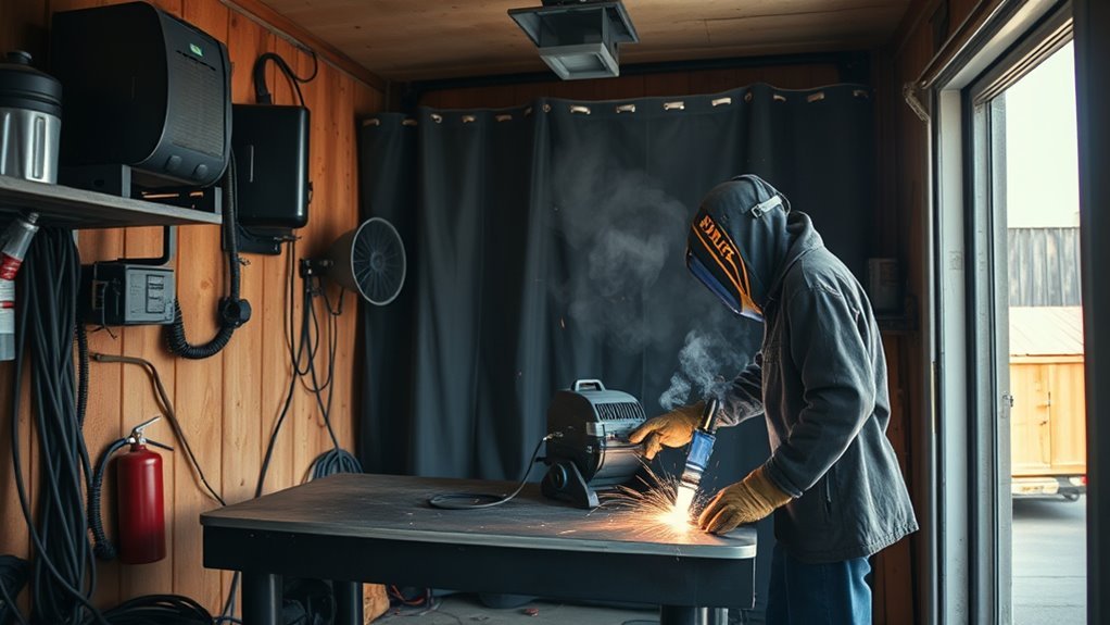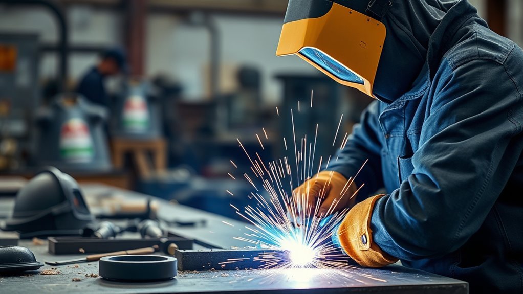
Rough cuts, hidden coatings, dross, and poor fit-up can create weld problems before you strike an arc. A plasma cutter can trim, pierce, bevel, and shape electrically conductive metal quickly, but the cut is only the first part of the job. To prepare a weld-ready joint, you also need safe hot-work controls, the correct air and consumables, a planned cut line, and careful edge cleanup.
Quick Answer
To prep metal for welding with a plasma cutter, identify the metal and coatings, secure the workpiece, connect the work clamp to clean metal, and use the machine’s cut chart for consumables, amperage, air, and speed. After cutting, remove dross, oxide, burrs, paint, oil, and scale, then check the bevel and fit-up before welding.
Key Takeaways
- Treat plasma cutting as hot work: protect your eyes and skin, control fumes, remove combustibles, and never cut an unprepared container.
- Use clean, dry, oil-free air and follow your exact machine’s cut chart instead of relying on a universal pressure or amperage setting.
- Plan for kerf width, cut bevel, joint angle, and the side of the line you need to keep.
- Use a steady torch angle and speed; sparks should generally exit through the bottom of a complete cut.
- A plasma-cut edge is not automatically weld-ready. Remove dross and contamination, then inspect the joint for clean, consistent fit-up.
At a Glance
| Time Required | About 20 to 45 minutes for a basic job; longer for thick plate, multiple joints, coatings, or precision beveling |
| Difficulty | Beginner to intermediate, depending on metal thickness and joint accuracy |
| Tools Needed | Plasma cutter, suitable air supply, work clamp, PPE, measuring tools, clamps, and edge-cleaning tools |
| Cost | Low if you already own the equipment; consumable and abrasive use varies by the job |
What’s in This Article
- Essential Safety Precautions for Using a Plasma Cutter
- What You Need Before You Start
- Inspect, Identify, and Lay Out the Metal
- How to Set Up Your Plasma Cutter
- Preparing Your Workspace for Cutting
- Step-by-Step Plasma Cutting Weld Prep
- Plasma Cutting Techniques and Tips
- Piercing and Gouging Techniques
- Cleaning Plasma-Cut Edges for Welding
- When to Replace Consumables
- Factors Affecting Cutting Quality
- Post-Cutting Procedures and Maintenance
- Frequently Asked Questions
Essential Safety Precautions for Using a Plasma Cutter
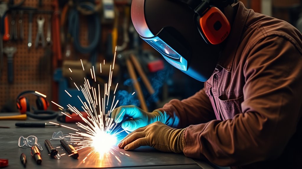
Plasma cutting is an arc-cutting process, so protect yourself from electric shock, ultraviolet and infrared radiation, hot sparks, molten metal, noise, and fumes. Wear safety glasses with side protection under a cutting helmet or face shield, use the filter shade recommended by the plasma cutter manufacturer, and cover exposed skin with flame-resistant clothing, leather gloves, and suitable footwear. The OSHA welding and cutting standard requires suitable eye, face, and protective-clothing controls for arc cutting in covered workplaces.
Remove combustible material from the spark path, including items behind or below the work. In workplace settings, OSHA says appreciable combustibles should be moved at least 35 feet away where practical, or protected when they cannot be moved. Keep an appropriate fire extinguisher nearby, inspect hidden spaces where sparks may travel, and maintain a fire watch when the conditions require one.
Use proper ventilation to manage fumes. Paint, plating, galvanizing, stainless steel, and unknown coatings can create hazardous fumes when heated. General airflow is not always enough; local exhaust, respiratory protection, or professional industrial-hygiene controls may be necessary. A disposable dust mask does not make unknown metal safe to cut.
Keep cutting leads, air hoses, and power cords dry and out of walkways. Do not stand in water or handle the torch with wet gloves. Water tables and approved water-cutting systems are valid tools, but only use water when the equipment and work procedure are designed for it.
Warning: Never plasma-cut a used drum, tank, pipe, sealed tube, pressure vessel, or other container until a qualified person has cleaned, isolated, vented, and verified it safe for hot work. Do not cut unknown coatings or metal that may contain hazardous substances.
Inspect the plasma cutter before every job. Look for damaged power cords, cracked torch bodies, cut or burned leads, loose air fittings, missing safety parts, blocked vents, and damaged consumables. Follow the owner’s manual for input power, duty cycle, air quality, maintenance, and safe operating limits.
What You Need Before You Start
Gather the equipment before you power on the cutter. A complete setup reduces interruptions and helps you avoid reaching across hot metal or taking unsafe shortcuts.
- Plasma cutter with the correct torch, shield, nozzle or tip, electrode, and swirl ring or cartridge
- Clean, dry, oil-free compressed air or the gas supply specified by the manufacturer
- Air filter, separator, or dryer when required by the air system and local humidity
- Work clamp with a clean electrical contact point
- Safety glasses, properly shaded cutting helmet or face shield, flame-resistant clothing, gloves, hearing protection, and suitable footwear
- Stable metal table, cutting grate, or another noncombustible support
- Clamps or fixtures that hold the work without crossing the planned torch path
- Marker, square, tape measure, straightedge, templates, and bevel gauge when needed
- File, scraper, wire brush, grinder, flap disc, or nonwoven abrasive for edge cleanup
- Dedicated stainless steel brushes and abrasives when preparing stainless steel or aluminum
Before cutting, remove oil and grease from the area, then remove loose rust, heavy scale, paint, or coating along the cut path when it is safe to do so. Clean metal helps stabilize the arc and reduces contamination that would otherwise remain on the weld edge. Use a product intended for metal preparation, follow its safety data sheet, and keep chlorinated solvent vapors away from hot work. For a fuller cleaning workflow, see how to clean metal before welding when that guide is available.
Note: The plasma cutter’s work clamp completes the cutting circuit. It is not a substitute for the equipment grounding and electrical protections required by the machine and local code.
Products Worth Considering

Package Include: 10 Shield Cups, 50 Nozzles, 20 Swirl Baffle, and 30 Electrodes.

[Achieve Precise Cuts] PT31 Plasma Cutting Consumables – Your Essential Tool for Efficient Cutting! Whether you're working with sheet metal, steel, or any other material, superior cutting performance ensure clean, accurate, and smooth cuts.
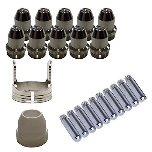
Only Compatible with BROWN Color Lotos LTP5800D , LTP5000D, LTPDC2000D.
Inspect, Identify, and Lay Out the Metal
Confirm what you are cutting before you set the machine. Air-plasma systems commonly cut electrically conductive metals such as carbon steel, stainless steel, and aluminum, but settings, edge chemistry, fumes, and cleanup needs differ by material. Stop if the alloy, coating, previous contents, or internal condition is unknown.
Inspect the Workpiece
- Check both sides for paint, plating, galvanizing, oil, seam sealer, undercoating, insulation, or trapped debris.
- Look for cracks, deep rust, laminations, thin spots, previous welds, or heat-sensitive parts near the cut.
- Inspect hollow sections for capped ends, trapped pressure, liquid, foam, or combustible residue.
- Verify that the part will remain stable after the cut and that the offcut cannot fall onto you, a hose, or a power lead.
Plan the Cut and Weld Joint
Mark the finished joint line and the waste side. A plasma arc removes a strip of metal called the kerf, and handheld cuts can leave some bevel. Leave a small cleanup allowance when final dimensions or root gaps matter, then grind or machine to the finished line.
Plan the joint before cutting. A square butt joint, lap joint, fillet joint, and groove weld do not use the same edge shape. Thick material may need a bevel, root face, and root opening based on the drawing, welding procedure, code, or engineer’s requirements. Do not guess joint dimensions on structural, pressure, vehicle-safety, lifting, or other critical work.
Pro Tip: Mark both the cut line and the keep side. On precision work, make a scrap cut first, measure the actual kerf and bevel, and offset your guide before cutting the final part.
How to Set Up Your Plasma Cutter
Use the machine’s manual and cut chart as the final authority. Plasma systems differ in input power, consumables, output current, air flow, inlet pressure, automatic pressure controls, torch design, and maximum pierce thickness. Also follow local electrical codes when you connect power or install a dedicated circuit.
Products Worth Considering

High-Quality Material:Made of high quality material to ensure a longer lifespan and superior performance.

10 pcs TIPS (Extended) /10 pcs ELECTRODE (Extended) /10 pcs SHIEDED-CUP/10 pcs GAS RING

⚡【Precision Compatibility】 Exact fit for YESWELDER CUT 55DS Pro & 65DS (2019-2024 models). Replaces OEM# IPT40-55DS/65DS.
Essential Equipment Checklist
- Confirm the input voltage, phase, plug, circuit capacity, and extension-cord limits listed for the machine.
- Verify that the compressor can maintain the required flow at the specified pressure while air is flowing, not only while static.
- Drain the compressor and moisture separator, then check filters and air lines for water, oil, dirt, and leaks.
- Install the exact consumable set for the torch, material, operation, and amperage.
- Connect the work clamp to clean bare metal on the workpiece or an approved cutting table with a reliable path to the work.
- Check that the torch lock, trigger guard, retaining cap, and other safety interlocks work as designed.
There is no universal air setting. For example, current Hypertherm models list different requirements ranging from about 4 scfm at 80 psi on one compact system to more than 9 scfm at 90 psi on a larger system. Other brands and torches differ, and some machines adjust pressure automatically. Use the exact specification for your model and confirm that pressure does not collapse during the cut.
Step-by-Step Setup Guide
- Place the machine where cooling air can circulate and where sparks cannot enter the case.
- With the power off, inspect and install the correct consumables in the order shown in the torch manual.
- Connect the approved power source and air supply.
- Set or verify air flow in the machine’s test or purge mode when the manufacturer provides one.
- Attach the work clamp to a clean contact point near the cutting area without placing it on the piece that will fall away.
- Select the process and amperage shown in the cut chart for the metal, thickness, and installed consumables.
- Set up a guide or template when the cut must be straight, round, or dimensionally accurate.
- Make a short test cut on scrap from the same material and thickness.
Preparing Your Workspace for Cutting
Choose a stable, noncombustible surface and clear the area around, below, and behind the workpiece. Organize the tools so you can move the torch through the full cut without pulling a lead across hot metal. Secure the work, but keep clamps and supports out of the torch path.
Use proper ventilation in the work area and position local exhaust so it captures fumes without pulling sparks toward combustible filters or disturbing the cutting arc. Move unprotected people and animals out of the area, and use suitable screens to protect others from arc radiation and sparks.
Safety Precautions First
Use these checks before each cut:
| Safety Measure | What to Check |
|---|---|
| Personal protective equipment | Eye and face protection, flame-resistant clothing, dry gloves, hearing protection, and covered footwear are in place. |
| Cutting surface | The table is stable, noncombustible, and open beneath the cut so the arc is not reflected toward the torch. |
| Fire control | Combustibles are removed or protected, hidden spark paths are checked, and an extinguisher is available. |
| Ventilation | Fumes are captured or diluted without exposing other people or recirculating contaminated air. |
| Leads and hoses | Cables are dry, undamaged, clear of the cut, and protected from falling offcuts. |
| Workpiece support | The keep piece and offcut will remain controlled when the cut finishes. |
Organize Your Tools
Keep spare consumables in clean packaging and separate used parts from new ones. Place layout tools away from the spark stream. Set aside a marked cooling area for hot pieces and a separate container for sharp scrap. Good organization prevents burns, trip hazards, and accidental reuse of damaged consumables.
Step-by-Step Plasma Cutting Weld Prep
- Identify the metal and hazards. Confirm the base metal, thickness, coating, previous contents, and required joint design.
- Clean the cut zone. Remove oil first, then safely remove loose scale, heavy rust, paint, and coating from the cut and weld area.
- Lay out the joint. Mark the finished edge, kerf allowance, keep side, waste side, bevel, and any lead-in or pierce location.
- Support and clamp the work. Prevent movement, vibration, pinching, and uncontrolled falling when the cut completes.
- Inspect and set up the cutter. Install matched consumables, connect clean air and power, attach the work clamp, and use the model-specific cut chart.
- Make a test cut. Check penetration, dross, bevel, kerf width, and travel speed on scrap of the same material and thickness.
- Cut with steady motion. Keep the torch at the specified drag position or standoff, hold it square unless beveling, and maintain a consistent speed.
- Let the metal cool safely. Mark or isolate hot parts and keep the post-flow air cycle unobstructed.
- Clean the edge. Remove dross, burrs, oxide, coating, oil, and scale without rounding away required joint dimensions.
- Verify fit-up. Check straightness, bevel angle, root face, root opening, and contact between parts before tacking or welding.
Plasma Cutting Techniques and Tips
Good torch control reduces cleanup. Use a drag shield only when the torch and consumable set are designed for drag cutting. Otherwise, maintain the standoff specified in the cut chart. Many handheld systems use a standoff near 1/8 inch for certain operations, but the correct distance depends on the torch and consumables. Maintaining a consistent torch standoff distance helps keep the arc stable.
Start an edge cut with the torch square to the plate and the nozzle positioned as the manual directs. Once the arc transfers, move smoothly. Watch the sparks beneath the work: on a complete cut, they should pass through the plate and trail slightly behind the torch. Sparks spraying back from the top often indicate excessive speed, insufficient power, too much standoff, poor air flow, or material beyond the machine’s capacity.
Moving too slowly can widen the kerf, increase heat input, round the top edge, and create low-speed dross. Moving too fast can leave incomplete penetration, a heavily lagging arc, and high-speed dross. Hypertherm’s plasma cutting mistake guide recommends using the proper cut speed and matched consumables rather than treating dross as one single-setting problem.
For straight cuts, clamp a guide at the correct offset for the torch body and kerf. Keep the guide clean so the torch does not lift or tilt. For circles and curves, turn your body and lead position before starting so you do not stop midway or twist the torch.
Pro Tip: Change only one variable at a time during a test cut. Start with the cut chart, then correct air delivery and consumable condition before making small travel-speed adjustments.
Piercing and Gouging Techniques
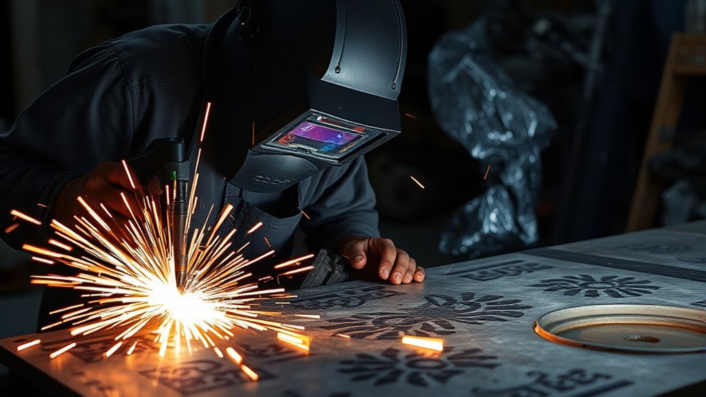
Piercing and gouging can help create holes, remove defective weld metal, or rough in a bevel, but both operations are harder on consumables than an edge start. Never pierce material thicker than the machine’s rated pierce capacity.
How to Pierce Metal
Thin material may allow a straight-down pierce when the manual permits it. On thicker material, start with the torch tilted so molten metal can escape away from the nozzle and your body, then roll the torch upright after the arc breaks through. Many handheld-machine guides use a starting angle around 45 degrees, but follow the method and distance shown for your torch. Do not move onto the cut path until the pierce is complete.
How to Gouge Metal
Install the manufacturer’s gouging consumables and select gouging mode when provided. Hypertherm’s handheld plasma gouging guidance starts with the torch near a 40-degree angle and the nozzle close to the work before firing. The operating distance, speed, current, and angle control the groove depth and width, so use the manual instead of a universal arc-length number.
| Operation | Starting Position | Main Control |
|---|---|---|
| Edge cutting | Square to the plate at the specified drag position or standoff | Steady speed and complete arc penetration |
| Piercing | Tilted on thicker metal, then rolled upright after breakthrough | Blowback control and rated pierce capacity |
| Gouging | About 40 degrees as a common manufacturer starting point | Matched gouging consumables, angle, speed, and distance |
Match the tip size to amperage and never run a nozzle above its rating. Make shallow gouging passes until you understand how quickly the process removes metal. Deep, uncontrolled gouges can reduce the required section thickness or leave an irregular surface that needs more repair.
Cleaning Plasma-Cut Edges for Welding
Let the part cool enough to handle safely, then remove all loose dross with a scraper, file, chipping tool, or grinder. Clean the cut face and the adjacent weld zone to sound metal. Remove burrs and sharp corners, but do not grind away the specified root face, bevel, or final dimension.
Hold the parts in their welding position and inspect the entire joint. The edges should meet the drawing or welding procedure without large, changing gaps. Correct high spots, cut bevel, distortion, and misalignment before tacking. A visually clean edge does not compensate for poor joint geometry.
Mild Steel
Remove dross, loose oxide, paint, rust, oil, and mill scale from the weld zone to the level required by the welding process and procedure. Grind away any hardened lumps or deep drag lines that prevent consistent fit-up.
Stainless Steel
Use abrasives and stainless steel brushes reserved for stainless work. Carbon-steel dust or a previously used carbon-steel brush can contaminate the surface and contribute to later rust staining. Cutting stainless also requires effective fume control; OSHA specifically requires adequate mechanical ventilation for certain stainless cutting operations in covered workplaces.
Aluminum
Remove oil and grease with an approved nonchlorinated cleaner before brushing. Then remove the oxide from the joint with a clean stainless steel brush dedicated to aluminum and weld soon after cleaning. Miller’s industrial aluminum welding guide recommends solvent cleaning before stainless-steel wire brushing.
Coated or Galvanized Metal
Identify the coating and use a documented removal and ventilation procedure. Do not assume that grinding a narrow strip makes the job safe. Zinc, lead, cadmium, paint pigments, sealers, and other coatings may require local exhaust, respiratory protection, exposure assessment, or professional removal. The OSHA welding chemical-hazard overview explains that cutting and welding fumes depend on both the base metal and its coatings.
Note: Avoid chlorinated brake cleaners and chlorinated degreasers around cutting and welding. Heat and ultraviolet radiation can create highly toxic decomposition products. Follow the cleaner manufacturer’s instructions and allow approved cleaners to evaporate fully before hot work.
Weld-Ready Edge Checklist
- No loose dross, slag, burrs, or sharp projections remain.
- The weld zone is dry and free from oil, grease, paint, plating, and loose oxide.
- The edge has no deep gouges, cracks, laminations, or severe undercut from cutting.
- The bevel angle, root face, root opening, and part alignment match the drawing or procedure.
- Clamps can hold the parts without forcing a poor fit or closing a required root gap.
- The planned weld sequence will not trap contaminated surfaces inside the joint.
When to Replace Consumables for Optimal Performance
Inspect consumables before blaming the machine or changing settings. Replace parts according to the torch manual when the arc becomes unstable, starting becomes unreliable, cut angularity increases, the kerf widens, or cut quality remains poor after air and technique checks.
- Nozzle or tip: Replace it if the orifice is enlarged, oval, nicked, burned, or no longer round and centered.
- Electrode: Check the emitter pit against the manufacturer’s wear limit. Do not judge every electrode by one universal pit depth.
- Shield or drag shield: Clean blocked gas holes and replace cracked, burned, distorted, or heavily spattered parts.
- Swirl ring, retaining cap, or cartridge: Check for cracks, blocked passages, damaged seals, and incorrect assembly.
Do not try to restore damaged nozzles or electrodes by drilling, filing, or reshaping their precision openings. Replace them with genuine or manufacturer-approved parts that match the torch and current range. Dirty, oily air can shorten consumable life, so correct the air problem before installing another set.
Factors Affecting Cutting Quality
Cut quality comes from the whole system: material condition, input power, air quality and flow, matched consumables, work-clamp contact, standoff, torch angle, travel speed, and machine capacity. Adjusting amperage alone will not correct every problem.
Start with the manufacturer’s cut chart. Then verify air delivery and consumable condition before changing travel speed.
| Symptom | Likely Checks | Correction |
|---|---|---|
| Arc does not transfer | Work-clamp contact, paint or rust at the contact point, consumable assembly, air pressure, trigger lock | Restore clean contact, inspect the torch, and follow the fault code or manual |
| Cut does not go through | Travel too fast, low available output, low flowing air, excessive standoff, worn consumables, metal too thick | Return to the cut chart, correct air delivery, reduce speed within the chart range, or edge-start within rated capacity |
| Heavy bottom dross | Speed too slow or too fast, wrong current for the consumables, excessive standoff, poor air quality | Use a scrap test and adjust one verified variable at a time |
| Large bevel or angled edge | Torch tilted, worn nozzle, wrong cutting direction, excessive speed, standoff error | Hold the torch square, replace damaged parts, and confirm direction and speed |
| Consumables fail quickly | Wet or oily air, piercing blowback, incorrect assembly, wrong parts, over-current operation | Improve filtration, use proper piercing technique, and install matched parts correctly |
| Edge will not fit tightly | Kerf not allowed for, guide offset wrong, heat distortion, dross or high spots | Re-measure, straighten or re-cut as appropriate, and finish the edge to the required geometry |
Hypertherm’s dross troubleshooting guide shows that high standoff, low amperage for the selected process, and travel-speed errors can all contribute to dross. Matching amperage to material thickness is useful only when the installed consumables and machine chart support that current.
Post-Cutting Procedures and Maintenance
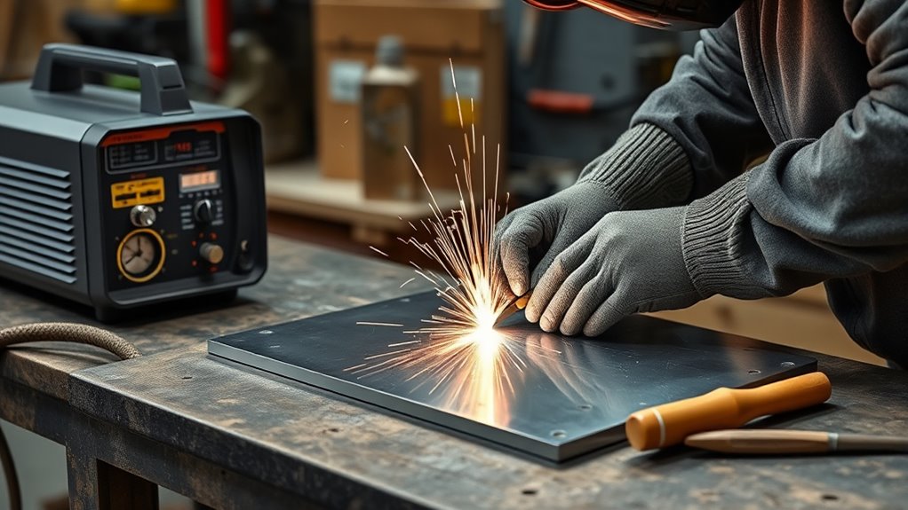
When the cut ends, release the trigger and let the torch complete its post-flow cooling cycle. Keep the nozzle clear of hot dross while the air runs. Turn off the machine according to the manual, isolate power before servicing the torch, and shut off the air supply when the work is finished.
Do not handle fresh-cut metal with bare hands. Use pliers or dry gloves, place hot pieces in a marked cooling area, and warn other people that the material is hot. Check the work area, floor, wall cavities, and the opposite side of partitions for smoldering material after the cut.
To maintain the equipment:
- Inspect and clean the torch exterior, shield, and gas passages without altering precision openings.
- Replace worn electrodes, nozzles, shields, O-rings, or cartridges as the manufacturer directs.
- Drain moisture from the compressor and separators, and service filters on schedule.
- Check the torch lead, work lead, air line, fittings, strain reliefs, and power cord for heat or physical damage.
- Coil leads loosely without sharp bends and store the machine and consumables in a clean, dry location.
- Review the correct amperage settings and cut chart before the next job rather than relying on the previous setup.
Finish by cleaning and inspecting the cut edge before welding. Remove dross, sharp burrs, paint, oil, loose scale, and process oxide, then dry-fit and clamp the joint. Begin welding only after the edge geometry and cleanliness meet the drawing, procedure, and service requirements.
Frequently Asked Questions
Can I use a plasma cutter to weld?
No. A plasma cutter removes metal to cut, pierce, or gouge it. A welding power source and suitable welding process join metal. The plasma cutter can prepare the shape and edge, but you still need to clean and fit the joint before welding.
How do you prep metal before welding after plasma cutting?
Remove dross, burrs, process oxide, paint, oil, rust, and loose scale from the weld zone. Then check the bevel, root face, root opening, straightness, and alignment. Use material-specific tools so you do not contaminate stainless steel or aluminum.
Should the plasma torch touch the metal?
Only when the torch and installed shield are designed for drag cutting. Some setups let the shield slide on the plate, while others require a set standoff. Follow the torch manual; do not press an unshielded nozzle against the work.
Do you need a welding shield when using a plasma cutter?
You need suitable eye and face protection for arc cutting. Wear safety glasses under a properly shaded cutting helmet or face shield, and use the shade recommended for your machine and output current. Protect nearby people with screens or appropriate eye protection.
Why does my plasma cut leave so much dross?
Common causes include incorrect travel speed, excessive standoff, low flowing air, moisture or oil in the air, worn consumables, mismatched amperage and nozzle, or material beyond the machine’s clean-cut capacity. Return to the cut chart and check one variable at a time.
Should I grind the edge after plasma cutting?
Usually, yes, when the edge will be welded. Remove dross and contamination and correct any high spots or bevel errors. Grind only as much as needed so you do not change the required joint dimensions or make the edge too thin.
Can I plasma-cut painted or galvanized metal?
Only after identifying the coating and controlling the fumes and fire hazards. Some coatings can release highly hazardous substances. Remove coatings with an approved procedure and use the ventilation, respiratory protection, and exposure controls required for the material.
How close should the work clamp be to the cut?
Place it on clean bare metal where it has a reliable electrical path to the work, preferably reasonably near the cutting area. Keep it off the falling offcut and away from locations where heat, sparks, or the torch can damage the clamp or lead.
Safety Disclaimer: This article provides general information and does not replace the plasma cutter manual, a welding procedure specification, code requirements, hazard assessment, electrical work by a qualified person, or workplace safety training. Follow the rules that apply to your machine, material, and job site.
Conclusion
Good plasma-cut weld prep starts before the arc. Identify the metal and coatings, plan the joint and kerf allowance, control the hot-work hazards, and set the cutter from its own manual and cut chart. A steady torch, dry air, matched consumables, and a scrap test will reduce avoidable dross and bevel.
After cutting, treat the edge as unfinished until you remove contamination and verify the joint geometry. Clean the material with tools suited to the alloy, inspect the bevel and fit-up, and correct defects before tacking. That process reduces rework and gives the welding operation a consistent, weld-ready joint.
Sources
- OSHA 29 CFR 1910.252: General Requirements — fire prevention, containers, eye protection, ventilation, and hot-metal warnings
- OSHA Welding, Cutting, and Brazing Chemical Hazards — fumes from base metals, coatings, and cleaning residues
- Miller: How to Select and Operate a Hand-Held Plasma Cutter — standoff, travel speed, spark direction, and cutting sequence
- Hypertherm: 10 Common Plasma Cutting Mistakes — consumable selection, cut speed, and dross prevention
- Hypertherm: Plasma Cutter Gouging Techniques — gouging consumables, angle, and torch positioning
- Miller: Guide to Industrial Aluminum Welding — aluminum solvent cleaning and dedicated stainless-steel brushing