To visually inspect a weld for defects, first make the weld and nearby base metal clean, safe, well lit, and accessible. Review the drawing, weld symbol, welding procedure specification, inspection plan, and governing acceptance criteria before judging the joint. Then inspect and measure the weld before welding, between passes when required, and after completion. Visual testing can reveal surface discontinuities, but it cannot prove that the inside of a weld is sound.
Quick Answer
Clean the weld and nearby metal, provide bright glare-free light, and inspect the face, both toes, ends, and accessible root. Measure weld size, profile, undercut, reinforcement, and alignment. Compare every indication with the drawing, WPS, governing code, and project acceptance criteria before accepting, repairing, or requesting further testing.
Key Takeaways
- A weld must be clean, visible, accessible, and cool enough to inspect safely.
- Review the WPS and the separate acceptance criteria before deciding whether an indication is allowed.
- Check the joint before welding, inspect each pass when required, and examine the completed weld from several angles.
- Look for cracks, porosity, undercut, overlap, underfill, slag, arc strikes, poor profile, distortion, and visible root problems.
- Visual testing finds accessible surface conditions. Hidden fusion, penetration, or volumetric problems may require another NDT method.
- Record the type, size, location, disposition, repair, and reinspection result for every reportable indication.
At a Glance
| Time Required | Several minutes for a clean, accessible small weld; longer when cleaning, measurements, restricted access, documentation, or additional testing are required |
| Difficulty | Basic screening is beginner-friendly; code acceptance and critical-weld inspection require suitable training and authorization |
| Tools Needed | Flashlight, inspection mirror, magnifier, weld gauge, ruler, temperature device when specified, checklist, marker, camera, and required PPE |
| Cost | Basic tools may already be available; certified inspection, remote viewing equipment, and added NDT are project-dependent |
Why Visual Weld Inspection Matters for Quality Assurance
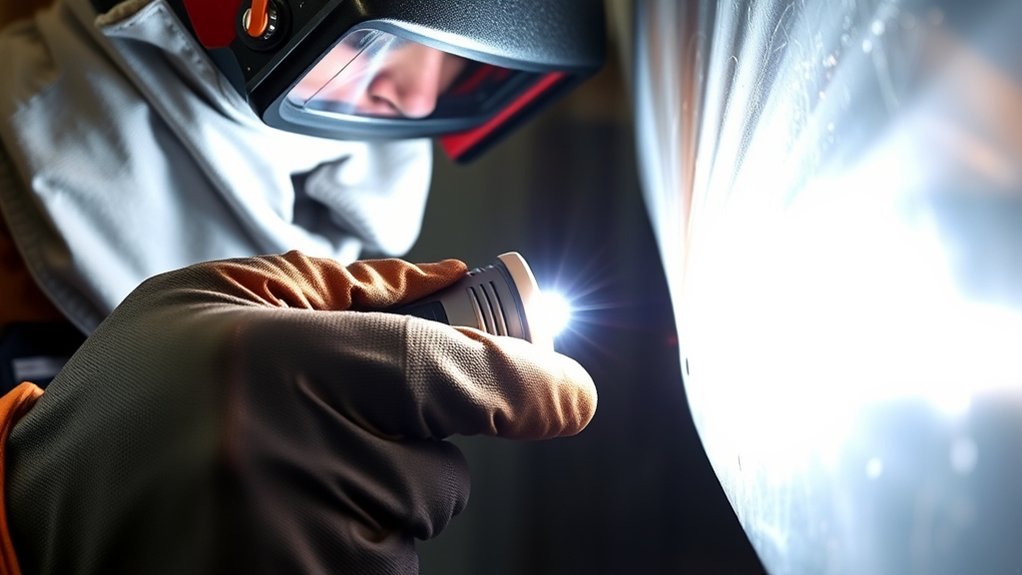
Visual testing is one of the fastest ways to find accessible surface problems and dimensional errors before a welded part moves to the next operation. It can be performed before welding, during fabrication, and after the weld is finished. The AWS guide for visual examination of welds covers these stages, along with personnel, equipment, surface conditions, and records.
Inspection can reveal cracks, surface porosity, undercut, overlap, underfill, excessive reinforcement, crater problems, arc strikes, distortion, poor alignment, and an irregular bead profile. Finding these conditions early can prevent the same process problem from affecting several joints.
Visual inspection also gives the welder, supervisor, and quality team specific information to act on. A useful report identifies the weld, location, indication type, dimensions, relevant acceptance requirement, and proposed disposition. The next step may be cleaning, measurement, approved repair, process correction, engineering review, or additional nondestructive testing.
Basic inspection often requires only a light, mirror, gauge, magnifier, ruler, checklist, and camera. More complex work may need a borescope, videoscope, calibrated measuring equipment, written inspection procedure, or qualified inspector. The applicable code, drawing, contract, or quality plan determines what is required.
Understanding the five parameters of welding can help you connect a visible condition with possible causes such as heat input, travel speed, arc length, electrode angle, or wire-feed settings. However, appearance alone does not prove the cause.
A smooth-looking weld can still contain hidden discontinuities. Visual inspection is the first quality check, not proof of complete internal fusion.
Note: This guide supports general visual screening. It does not replace the governing welding code, an approved inspection procedure, engineering requirements, or a qualified inspector for safety-critical work.
Know the Difference Between a Discontinuity and a Defect
A discontinuity is an interruption in the normal structure, shape, or appearance of the weld or base metal. Examples include a pore, a shallow groove, a profile change, or a visible indication that needs evaluation.
A defect is a discontinuity that fails the applicable acceptance criteria. The same type or size of indication may be allowed in one application and rejected in another because the materials, joint design, loading, service conditions, and governing standard differ.
Do not make a final pass-or-fail decision from appearance alone. Compare the indication with the drawing, weld symbol, contract specification, inspection plan, and governing standard. ISO 17637 is one recognized standard for visual testing of fusion-welded joints, but it does not automatically govern every project.
Preparing for a Visual Weld Inspection
Before inspecting, make the area safe and confirm what requirements apply. Dirt, paint, oil, rust, slag, scale, spatter, poor access, glare, and weak lighting can hide surface indications or make the weld appear different from its true profile.
Review both the welding and inspection documents. A welding procedure specification explains how the weld should be made. Acceptance limits may come from a separate code, drawing, project specification, customer requirement, or inspection procedure.
Wear the PPE required for the site and task. Even after the arc stops, the work can remain hot, sharp, electrically hazardous, or contaminated with spatter. OSHA identifies burns, eye injury, cuts, electrical shock, fumes, and ultraviolet radiation among the hazards associated with welding work. Review the applicable OSHA welding hazard guidance and your workplace procedure.
Inspector Readiness and Document Review
Before beginning a formal inspection, confirm that the inspector is trained and authorized for the work. Project requirements may address visual acuity, color perception, experience, certification, and periodic eyesight checks.
Confirm the following:
- The weld, joint, and inspection stage are correctly identified.
- The drawing and weld symbol revision are current.
- The correct WPS and supporting fabrication instructions are available.
- The acceptance standard and any customer-specific limits are known.
- Required hold points and witness points have been observed.
- Measuring tools are clean, undamaged, suitable for the joint, and verified or calibrated when required.
- The surface can be viewed directly or with an approved remote visual device.
- The report form, weld map, or electronic record is ready.
Visual Inspection Tools
Basic visual inspection tools include a flashlight or headlamp, inspection mirror, magnifier, weld gauge, ruler, tape measure, marker, camera, and checklist. A temperature-indicating device may also be needed when preheat or interpass temperature must be verified.
A magnifying glass or jeweler’s loupe can help you examine a suspected crack, pore, slag line, crater indication, or other small surface condition. Magnification should support the required procedure, not replace adequate lighting or direct viewing.
A weld gauge can help measure:
- Fillet-weld leg length and, with the appropriate gauge, effective profile or throat-related dimensions
- Groove-weld reinforcement
- Undercut depth
- Concavity or convexity
- Mismatch or high-low
- Root opening and bevel preparation before welding
- Weld length, intermittent-weld pitch, and spacing
Choose a gauge designed for the measurement you need. Do not estimate a critical dimension by eye when the acceptance criteria give a numerical limit.
Inspection Environment Preparation
Use bright, even lighting that shows the surface without creating glare. Moving a light across the weld at a low angle can make ripples, grooves, lips, crater edges, and fine linear indications easier to see.
For direct visual testing, common guidance is to view the surface from within about 24 inches or 600 mm and at an angle of at least 30 degrees to the surface, unless the governing procedure sets another requirement. The ASNT overview of visual testing also explains the importance of lighting, access, viewing angle, and line of sight.
Clean loose slag, scale, dust, grease, oil, paint, and excessive spatter where the inspection procedure allows. Cleaning must not smear, peen, grind away, or conceal an indication. Do not use aggressive cleaning or metal removal until the condition has been documented and the repair process permits it.
Inspect the weld from the front, both sides, both toes, and each accessible end. Check starts, stops, tack welds, tie-ins, corners, craters, attachments, and the root side when it is accessible. Use an inspection mirror, borescope, or videoscope when direct viewing is not possible and remote visual testing is authorized.
Pro Tip: Photograph the weld before any repair or grinding. Include the weld number and a ruler or gauge in the frame so the location and scale remain clear.
Step-by-Step: How to Visually Inspect a Weld
- Identify the weld. Confirm the part, joint number, drawing revision, weld symbol, material, welding process, WPS, and inspection stage.
- Review the acceptance criteria. Know which code, drawing, project specification, or quality procedure controls dimensions and allowable discontinuities.
- Make the area safe. Isolate moving equipment when required, allow hot work to cool, wear suitable PPE, and confirm safe access.
- Clean without hiding evidence. Remove permitted slag, dirt, loose scale, and excessive spatter. Do not grind or blend a suspected defect before it is recorded and approved for repair.
- Inspect the joint before welding. Check material condition, bevels, root opening, alignment, backing, tack welds, cleanliness, and preheat when specified.
- Inspect during welding. Check each pass when required, remove slag, verify interpass temperature, watch joint movement, and confirm continued compliance with the WPS.
- Scan the completed weld systematically. Start at one end, follow the full face, inspect both toes, check the crater and stops, then inspect the adjacent heat-affected area and accessible root.
- Measure the weld. Check weld size, reinforcement, undercut, profile, length, pitch, mismatch, distortion, and other dimensions listed in the inspection plan.
- Classify each indication carefully. Record what you can observe without claiming hidden fusion, penetration, or internal soundness that visual testing cannot establish.
- Compare and document. Accept, reject, hold, or refer the weld according to the governing procedure. Record the disposition and any requirement for further NDT or repair.
Warning: Do not touch a recently welded joint or place your face, hands, mirror, camera, or gauge near hot metal until the inspection can be performed safely.
Common Weld Defects: What to Look For
Visible conditions can affect strength, fatigue life, fit, coating performance, appearance, or code acceptance. Cracks deserve immediate control, but other indications must still be measured and compared with the project criteria.
Each surface condition may have several causes. Dirty material, poor shielding, incorrect heat input, travel speed, joint preparation, electrode position, filler selection, or restraint may contribute. Use the indication to guide troubleshooting, but do not assign a root cause from appearance alone. Reviewing flux-core welding techniques can help when the indication occurred in a flux-cored weld.
| Visible Condition | What It May Look Like | Inspection Response |
|---|---|---|
| Crack | Fine straight, branching, transverse, longitudinal, toe, root, or crater line | Mark, photograph, isolate, and refer for disposition |
| Surface porosity | Round pits, pinholes, or clusters | Measure number, size, spacing, and affected length |
| Undercut | Groove beside the weld toe or root | Measure depth, length, location, and sharpness |
| Overlap or cold lap | Weld-metal lip rolled onto the base metal without a smooth transition | Treat as a possible surface fusion problem and evaluate to the criteria |
| Underfill or incomplete crater | Depression below the required surface or an unfilled stop crater | Measure profile and remaining thickness where required |
| Excess reinforcement or convexity | High, rope-like, sharply transitioned bead | Measure height and transition against the governing limit |
| Slag or surface inclusion | Dark linear pocket, trapped residue, or nonmetallic material | Clean as permitted, reinspect, and evaluate any remaining indication |
| Burn-through or melt-through | Hole, excessive root projection, or collapsed root area | Measure and refer to the joint-specific acceptance criteria |
| Arc strike | Local melted spot or scar outside the intended weld | Record the location and follow the required evaluation procedure |
| Mismatch or distortion | Offset edges, angular movement, bowing, twisting, or dimensional change | Measure against drawing and fabrication tolerances |
Cracks and Fractures
Cracks can seriously reduce the reliability of a welded joint. Look for visible separations on the weld face, toe, root, crater, heat-affected zone, tack weld, attachment, or nearby base metal.
A crack may appear as a straight line, branching line, crater star, transverse line, longitudinal line, or fine toe indication. It can result from several interacting factors, including restraint, rapid cooling, hydrogen, contamination, joint design, filler selection, or welding technique.
Record the length, location, orientation, and visible extent. Do not grind away a suspected crack before it is marked and photographed. Many welding requirements prohibit cracks, but the official disposition must follow the governing quality procedure.
Warning: Do not place a cracked or crack-suspect weld into service. Mark it, control the part, report it, and follow the approved evaluation and repair process.
Incomplete Fusion Issues
Incomplete fusion occurs when weld metal does not bond properly with the base metal or a previous weld pass. Some surface-breaking forms may be visible, but buried incomplete fusion cannot be confirmed or ruled out by sight alone.
Visible warning signs include a rolled-over bead edge, sharp unfused-looking boundary, poor wetting at the toe, an open seam between passes, or a bead that appears to sit on the surface rather than blend into it. These signs should be reported as observable conditions or suspected fusion problems.
Possible contributors include insufficient heat input, excessive travel speed, poor electrode angle, contamination, narrow joint access, incorrect preparation, or failure to clean between passes. When fusion inside the joint is in question, use the NDT method specified by the inspection plan.
Porosity and Voids
Surface porosity appears as round holes, pits, or clusters caused by gas cavities that open to the surface. Internal porosity cannot be evaluated fully by visual inspection.
Possible contributors include moisture, oil, paint, rust, contaminated filler, inadequate shielding, excessive arc length, drafts, or incorrect parameters. Record the pore diameter, number, spacing, distribution, and affected weld length. Then compare the results with the project limits.
| Condition | Suitable Initial Method | What to Record |
|---|---|---|
| Open surface pores | Visual testing and measurement | Size, count, spacing, distribution, and affected length |
| Suspected fine surface-breaking pores | PT or MT when permitted and suitable for the material | Indication pattern and examination area |
| Suspected internal porosity | RT or another specified volumetric method | Location, distribution, and evaluated severity |
| Acceptance decision | Governing code or project criteria | Accepted, held, repaired, or rejected |
Undercut, Overlap, and Poor Bead Shape
Undercut is a groove melted into the base metal beside the weld toe or root that is not filled with weld metal. It may reduce the local section and create a sharp stress concentration. Measure its depth, length, location, and continuity rather than judging it only by appearance.
Overlap occurs when weld metal flows onto the base metal without a properly fused transition. It may look like a lip, shelf, or rolled edge. Treat it as a possible surface fusion problem and compare it with the applicable criteria.
Also check for excessive convexity, concavity, underfill, excessive reinforcement, abrupt transitions, wandering bead width, inconsistent ripples, and an incomplete crater. A uniform-looking bead is desirable, but the required dimensions and profile control acceptance.
Slag Inclusions and Spatter
Slag inclusions occur when flux residue becomes trapped in or between weld passes. Surface slag may remain at the toe, between beads, or in a depression. Clean each pass as required before depositing the next one.
Spatter is not automatically a structural defect, but excessive spatter can hide the weld profile, interfere with coating or fit-up, and suggest unstable arc conditions. Remove it when the procedure requires and when removal will not conceal another indication.
If repair preparation uses a grinder, follow safe angle-grinder handling. Grinding is a separate preparation or repair operation, not a substitute for inspecting and documenting the original weld condition.
Other Visible Conditions to Check
- Incomplete penetration: It may be visible only when the root is accessible. A hidden root cannot be accepted based on the face appearance alone.
- Burn-through or excessive root reinforcement: Check accessible roots for holes, sagging, sharp projections, or excessive melt-through.
- Arc strikes: Record scars outside the intended weld area because they may require specific evaluation.
- Tungsten inclusions: A visible embedded tungsten particle may appear in GTAW work, but buried inclusions require another method to detect.
- Oxidation and discoloration: Evaluate color according to the material, welding process, shielding requirements, and project standard. Color alone is not a universal defect.
- Lamellar tearing or base-metal cracking: Inspect the adjacent base metal, not only the weld bead.
- Wrong weld location or missing weld: Compare every joint with the drawing and weld map.
- Incorrect intermittent-weld length or pitch: Measure the weld segments and spaces.
Tools and Techniques for Effective Inspection
Use a repeatable inspection pattern so no area is skipped. Start at one end, scan the face, inspect the near toe, inspect the far toe, check the stop crater, and then examine the adjacent base metal and accessible root.
Move the light instead of holding it in one position. Low-angle lighting makes raised and recessed features easier to see. A mirror can change the line of sight, while a magnifier can help evaluate a small indication after it has been located.
Use a weld gauge only for measurements it is designed to make. Seat the gauge on clean, stable surfaces and read it without rocking or forcing it. Record the measured value, unit, location, and acceptance limit.
Direct visual testing uses the unaided eye or simple aids such as mirrors and magnifiers. Remote visual testing uses equipment such as borescopes, fiberscopes, or videoscopes when direct access is limited. Confirm that the device resolution, lighting, scale, and procedure are suitable before using remote images for acceptance.
Do not overlook the heat-affected zone or surrounding base metal. Check for cracks, arc strikes, gouges, accidental grinding, distortion, coating damage, or material separation.
Finally, document photographs, dimensions, locations, and the applicable requirement. Clear records make corrective action and reinspection more reliable.
Products Worth Considering

【13 Pieces】This boxed weld inspection kit contains 13 tools, including 0-150mm rulers, welding gauges, micrometers, inspection mirrors, etc. Buying this boxed welding gauge kit can help you make various measurements and make welding more accurate
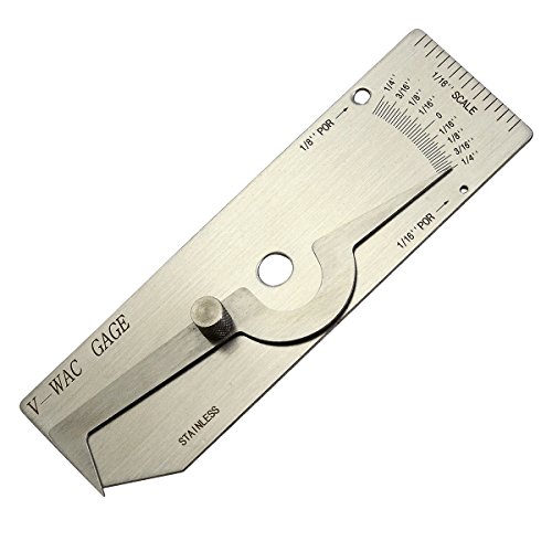
V-WAC Single Weld Gage

Telescopes from 7-1/2" to 21"
What to Check Before Welding: Your Pre-Weld Checklist
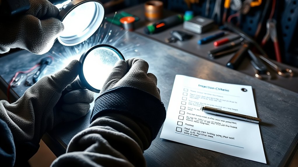
Many finished-weld problems begin before the arc is struck. A pre-weld inspection checks the material, joint, consumables, preparation, access, and procedure before those conditions become buried under weld metal.
| Item | Inspection Action | Why It Matters |
|---|---|---|
| Material identification | Confirm material, thickness, condition, and traceability when required | Prevents welding the wrong material or thickness |
| Joint preparation | Measure root opening, bevel angle, land, alignment, and backing | Supports access, fusion, penetration, and dimensional control |
| Surface condition | Remove prohibited oil, paint, rust, moisture, scale, and debris | Reduces contamination and shielding problems |
| Tack welds | Check location, size, soundness, cleanliness, and treatment required by the procedure | Prevents defective tacks from becoming part of the finished joint |
| Filler and electrode | Confirm classification, size, storage, condition, and compatibility | Keeps consumables consistent with the WPS |
| Preheat | Measure at the required location and time when specified | Supports heat control and cracking prevention |
| Equipment and settings | Confirm polarity, gas, flow, current, voltage, wire feed, and other WPS variables | Reduces process departures before welding begins |
| Restraint and sequence | Review clamps, fixtures, access, sequence, and expected shrinkage | Helps control distortion and locked-in stress |
| Documentation | Confirm current drawings, WPS, weld map, inspection plan, and acceptance criteria | Supports traceability and correct inspection decisions |
Correct machine settings depend on the process, material, joint, and procedure. A stick-welding amperage chart can provide general context, but the approved WPS and consumable guidance control production work.
Pre-Weld Inspection Questions
- Is the correct base material present and traceable when required?
- Is the metal clean, dry, and free from prohibited coatings or contamination?
- Does the root opening, bevel, land, alignment, and backing match the drawing and WPS?
- Are the correct filler metal, electrode, shielding gas, and polarity being used?
- Are tack welds clean, sound, correctly located, and acceptable for incorporation?
- Are machine settings within the permitted WPS range?
- Is the specified preheat established and measured correctly?
- Can the welder reach the joint while maintaining the required angle and travel path?
- Could clamps, fixtures, or joint restraint increase distortion or cracking risk?
- Are required hold points, inspector approvals, and environmental controls complete?
Key Considerations for During-Weld Inspection
During-weld inspection helps find process departures before they are covered by later passes. The required checks depend on the WPS, inspection plan, weld class, and project hold points.
For multi-pass welds, inspect and clean each pass when required. Remove slag, oxides, prohibited spatter, and other contamination before adding the next pass. Look for cracks, visible porosity, poor tie-in, irregular bead placement, an unfilled crater, or slag trapped along the toe.
Monitor preheat and interpass temperature when specified. Record the value, location, instrument, and time when the procedure requires documentation.
Check alignment and distortion as welding progresses. Shrinkage can close the root, pull the joint out of position, change the groove angle, or create excessive mismatch.
Confirm continued compliance with amperage, voltage, wire-feed speed, travel speed, electrode angle, shielding gas, heat input controls, bead sequence, and cleaning requirements. For galvanized material, review the hazards and controls related to zinc fumes during welding.
Warning: Never inspect close to an active arc without the required eye and face protection. OSHA requires suitable protection for welding operations and personnel exposed to arc radiation.
Visual Inspection After Welding: Evaluating Completed Joints
After welding, allow the joint to reach the inspection condition required by the procedure. Some materials, applications, and codes require a delay before final inspection because certain cracks may not appear immediately.
Clean the weld as permitted, then inspect the entire face, both toes, starts, stops, crater, attachments, adjacent base metal, and accessible root. Compare the finished joint with the drawing and weld symbol, not only with a general idea of what a good bead should look like.
Measure weld size, reinforcement, undercut, underfill, profile, length, pitch, mismatch, distortion, and any other specified dimension. If the joint preparation was produced by thermal cutting, reviewing the causes of poor plasma-cut quality may help explain irregular edges, excessive dross, or preparation problems.
Common Surface Discontinuities
Look for cracks, open porosity, undercut, overlap, underfill, excessive reinforcement, crater cracks, slag, arc strikes, melt-through, gouges, accidental grinding marks, and abrupt profile changes.
Measure rather than guess. A shallow-looking groove may exceed a numerical undercut limit, while a visible indication may still fall within the permitted criteria. Record both the observed value and the acceptance requirement used.
Check bead uniformity, but do not accept a weld only because it looks smooth. A regular surface does not confirm root penetration, sidewall fusion, or freedom from internal porosity.
Evaluating Weld Integrity Standards
A visual inspection determines whether accessible surface conditions and dimensions meet the governing requirements. It does not independently establish the complete structural integrity of the joint.
The applicable code or specification may define limits for crack indications, undercut, porosity, reinforcement, concavity, weld size, length, profile, and alignment. When the requirement is unclear, place the weld on hold and refer it to the responsible inspector, supervisor, engineer, or quality authority.
| Condition | What Visual Testing Can Do | Possible Next Step |
|---|---|---|
| Visible crack indication | Locate, photograph, and measure visible length | PT, MT, engineering evaluation, or approved repair as specified |
| Surface porosity | Count and measure visible pores | Compare with acceptance criteria; use RT if internal distribution must be assessed |
| Undercut | Measure depth, length, and location | Accept, repair, or refer according to the numerical limit |
| Suspected buried lack of fusion | Record visible warning signs only | Use the specified UT, RT, or other suitable method |
| Mismatch or distortion | Measure the finished geometry | Compare with drawing tolerances or engineering requirements |
When Visual Inspection Is Not Enough
Visual testing can evaluate only conditions that can be seen directly or through an approved remote viewing system. Use another NDT method when the inspection plan requires it or when a suspected discontinuity extends below the visible surface.
| Method | Main Capability | Important Limitation |
|---|---|---|
| Liquid penetrant testing (PT) | Reveals fine discontinuities that are open to the surface | Does not find sealed internal defects and generally requires a clean, nonporous surface |
| Magnetic particle testing (MT) | Finds surface and near-surface discontinuities | Works only on ferromagnetic materials and has limited depth capability |
| Ultrasonic testing (UT) | Can detect and locate internal discontinuities | Results depend on material, geometry, access, procedure, calibration, and operator skill |
| Radiographic testing (RT) | Produces an image of internal density and thickness changes | Requires radiation controls and may be less sensitive to some planar discontinuity orientations |
The governing inspection plan should select the method, technique, coverage, sensitivity, personnel qualification, and acceptance criteria. Do not substitute one method merely because its equipment is available.
Products Worth Considering

Standard grade kit

· Made of excellent material ☞ made of stainless steel, with a smooth surface through wire drawing process, thickened design, sufficient materials, not easy to rust, not easy to bend or deform, and long service life.

MADE OF EXCELLENT MATERIAL: This product is made of high-quality stainless steel and features a brushed finish with a smooth surface. The reinforced structure ensures excellent durability, corrosion resistance, and makes it resistant to bending and deformation.
How to Document Visual Weld Inspection Results
A report that says only “bad weld” or “looks good” does not provide enough information for traceability or corrective action. Record what was inspected, how it was inspected, what was observed, and which requirement controlled the decision.
For each weld or reportable indication, include:
- Project, part, assembly, and weld identification
- Drawing, WPS, inspection procedure, and revision numbers
- Inspection date, stage, location, and inspector identification
- Material and welding process when required
- Surface condition, access, lighting, and visual aids used when relevant
- Indication type and exact location
- Measured length, depth, height, diameter, spacing, or affected area
- Photograph, sketch, weld map, or coordinate reference
- Acceptance criterion and measured result
- Accepted, rejected, held, repaired, or referred disposition
- Additional NDT requested or completed
- Repair method, reinspection result, and record closure
Use neutral descriptions. Write “linear indication at the weld toe, approximately 12 mm long” rather than claiming “hydrogen crack” unless a qualified evaluation has established the cause.
Why Documenting Inspection Findings Is Crucial
Inspection records support traceability, communication, repair control, and trend analysis. They show which weld was inspected, what requirement applied, what the inspector found, and how the issue was closed.
Patterns across several reports can identify recurring process problems. Repeated porosity may lead the team to check cleaning, shielding gas, leaks, moisture, or filler storage. Repeated undercut may lead to a review of travel speed, heat input, torch angle, or joint access.
Records can also show whether corrective action worked. Compare the original indication, repair excavation, reweld, and final inspection instead of recording only the final result.
When recurring irregularities appear with an unstable arc, review possible arc-welding machine problems and solutions along with leads, connections, polarity, consumables, parameters, and operator technique.
Avoiding Common Pitfalls in Visual Weld Inspection
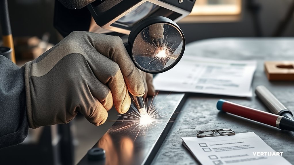
Rushing is one of the most common inspection errors. A quick glance from one position can miss a toe crack, shallow undercut, crater indication, root problem, or arc strike.
Avoid inspecting through slag, dirt, paint, oil, scale, or heavy spatter. Clean the area as the procedure permits, but do not grind away a suspected indication before documenting it.
Do not use poor lighting or stare at the weld from only one angle. Move the light, change your viewing position, and inspect both sides of the bead.
Do not confuse a smooth appearance with acceptable quality. Measure the dimensions and compare them with the governing criteria. Likewise, do not reject every visible irregularity without checking the permitted limits.
Do not use a damaged, unsuitable, or unverified gauge. A precise-looking reading is not reliable if the tool does not fit the measurement or cannot seat correctly.
Do not assign a hidden cause from surface appearance. Describe what you can see and recommend further evaluation where needed.
Inspect at the required stages instead of waiting until the joint is complete. Proper welding workspace setup also improves lighting, access, housekeeping, and safety.
What to Do After Finding Weld Defects?
When you find a reportable indication, mark and document it before altering the surface. Note the weld number, indication type, exact location, dimensions, and visible extent.
Notify the welding supervisor, inspector, quality representative, or engineer identified by the project procedure. Do not grind, gouge, weld over, or otherwise repair the area unless the approved process allows it.
Compare the indication with the acceptance criteria. The disposition may be acceptance as-is, engineering review, additional NDT, local repair, complete rework, or replacement.
When repair is authorized, remove the discontinuity by the approved method. Inspect the excavation before rewelding to confirm that the indication has been removed and that the excavation shape, remaining thickness, and surface condition are acceptable.
Correct the likely process contributors before rewelding. That may involve improved cleaning, different joint access, parameter adjustment, revised sequence, corrected fit-up, filler control, or review of the chosen welding process and its limitations.
After rewelding, perform the same required visual inspection and any additional NDT specified for the original weld or repair. Close the record only after the final result has been accepted by the responsible authority.
| Action | Required Response |
|---|---|
| Document the indication | Record type, location, dimensions, photograph, and weld identification before alteration |
| Control the part | Prevent unintended use or further processing when the procedure requires a hold |
| Evaluate the indication | Compare with the governing acceptance criteria and obtain the required disposition |
| Perform approved removal | Use the permitted grinding, machining, or gouging method without causing additional damage |
| Inspect the excavation | Confirm removal, acceptable shape, cleanliness, and remaining material before rewelding |
| Correct the process | Address cleaning, fit-up, parameters, consumables, access, technique, or sequence |
| Reinspect and close | Repeat the required VT and NDT, record the result, and obtain final acceptance |
Frequently Asked Questions
How do you inspect a weld visually?
Review the drawing, WPS, and acceptance criteria. Make the area safe, clean the weld, provide suitable lighting, and inspect the face, toes, ends, crater, surrounding metal, and accessible root. Measure required dimensions, record indications, and compare the results with the governing criteria.
How do you inspect welded workpieces for defects?
Inspect the joint preparation before welding, monitor required variables and pass condition during welding, and examine the cleaned finished joint afterward. Check dimensions, alignment, cracks, porosity, undercut, overlap, underfill, slag, arc strikes, distortion, and accessible root conditions.
What tools are used for visual weld inspection?
Common tools include a flashlight, inspection mirror, magnifier, weld gauge, ruler, tape measure, temperature device when specified, marker, camera, borescope, checklist, and required PPE. Formal inspection may require verified or calibrated measuring equipment.
What standard applies to visual inspection of welds?
The governing standard depends on the industry, material, joint, contract, and location. ISO 17637 and AWS B1.11 provide recognized visual-testing guidance, but the project code, drawing, specification, and inspection procedure determine the actual acceptance criteria.
Can visual inspection find internal weld defects?
No. Visual testing can identify accessible surface discontinuities and visible warning signs, but it cannot reliably evaluate hidden fusion, penetration, or internal porosity. UT or RT may be specified for internal evaluation. PT finds surface-breaking discontinuities, while MT finds surface and near-surface discontinuities in ferromagnetic materials.
Should a cracked weld always be repaired?
A crack indication should always be reported, controlled, and evaluated. Cracks are commonly prohibited, but the responsible quality authority must follow the governing code and repair procedure. Do not grind out or weld over a crack before it has been documented and approved for repair.
What is the difference between a weld discontinuity and a defect?
A discontinuity is an interruption in the normal structure, shape, or appearance of a weld. It becomes a defect when it exceeds the acceptance criteria that apply to the job. Not every visible irregularity is automatically rejectable.
What weld dimensions should be checked visually?
Depending on the joint and inspection plan, check fillet-weld size, groove-weld reinforcement, undercut, underfill, concavity, convexity, mismatch, root opening, weld length, intermittent-weld pitch, alignment, and finished distortion.
Conclusion
A dependable visual weld inspection is more than a quick look at the bead. It combines safe access, clean surfaces, suitable lighting, systematic viewing, accurate measurement, correct acceptance criteria, and complete records.
Inspect the joint before welding, monitor it during welding when required, and examine the finished weld from every accessible side. Look for cracks, porosity, undercut, overlap, underfill, slag, arc strikes, poor profile, distortion, and root problems. Describe only what you can observe, and use another NDT method when hidden conditions must be evaluated.
Most importantly, do not confuse appearance with proof of integrity. A consistent inspection process helps reduce rework, expose process problems early, and prevent an unacceptable weld from entering service.
Sources
- American Welding Society, AWS B1.11M/B1.11:2015 — visual-examination stages, personnel, equipment, surface conditions, and records
- International Organization for Standardization, ISO 17637:2016 — visual testing of fusion-welded joints
- American Society for Nondestructive Testing, Visual Testing — visual-testing principles, tools, viewing conditions, and limitations
- American Society for Nondestructive Testing, NDT Methods — capabilities of PT, MT, UT, RT, and other examination methods
- Occupational Safety and Health Administration, 29 CFR 1910.252 — welding, cutting, brazing, and personnel-protection requirements
- NASA-STD-5006A with Change 2 — public example of project-specific weld surface and dimensional requirements