
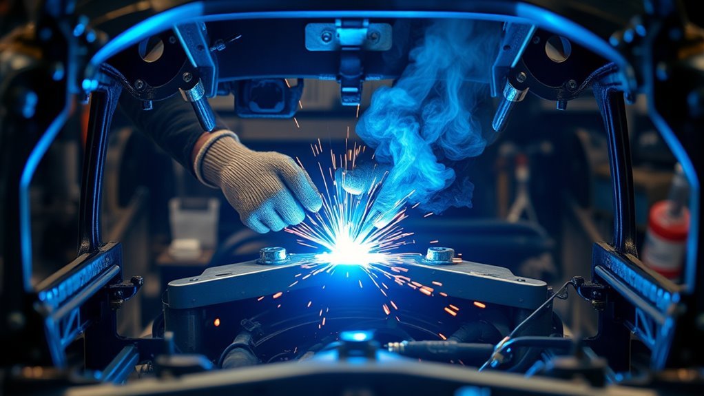
Welding an engine bay crossmember is a safety-critical fabrication job. The crossmember may carry engine and transmission loads, tie the chassis together, or locate steering and suspension parts. Before you cut anything, identify what the part supports, find the vehicle-specific repair or fabrication requirements, brace the structure, and mock up the complete drivetrain.
Quick Answer
To weld an engine bay crossmember safely, follow the vehicle maker’s structural repair guidance, support and brace the chassis, mock up the engine and transmission, confirm all clearances, prepare matching material, tack the assembly, recheck alignment, then complete and inspect the welds before corrosion protection and testing.
Key Takeaways
- Determine whether the crossmember carries only drivetrain loads or also supports steering, suspension, or frame loads.
- Use the vehicle-specific service or body repair manual to identify approved materials, sectioning points, attachment methods, and corrosion protection.
- Mock up the engine and transmission before final welding so you can verify mount position, driveline angle, steering movement, exhaust clearance, and service access.
- Treat the job as vehicle hot work: disable electrical systems as the manufacturer directs, protect fuel and brake parts, control fumes, and maintain a fire watch.
- Do not road-test the vehicle until weld quality, chassis dimensions, steering operation, fastener torque, and any required alignment or electronic checks are complete.
At a Glance
| Time Required | Project-dependent. Layout, bracing, repeated drivetrain mockups, welding, inspection, paint curing, alignment, and reassembly may take more than one working day. |
| Difficulty | Advanced. Structural design, vehicle measurement, and welding should be handled or approved by a qualified automotive fabricator. |
| Tools Needed | Rated stands or a lift, chassis braces or fixture, drivetrain hoist, plumb bob, straightedge, level, angle finder, measuring tools, grinder, cut-off tool, clamps, suitable welder, PPE, local fume extraction, fire extinguisher, torque wrench, and inspection lighting. |
| Cost | Varies widely with the vehicle, steel grade, replacement parts, mounts, fixtures, professional welding, alignment, inspection, paint, and any required calibration or scan work. |
Warning: Do not cut or weld a crossmember that carries engine, transmission, steering, suspension, crash, or frame loads unless you have the vehicle-specific procedure, suitable material, qualified welding skill, accurate measuring equipment, and a documented inspection plan. A weak or misaligned crossmember can make the vehicle unsafe.
Identify the Crossmember and Check the OEM Procedure
Start by identifying the exact part you plan to modify. A removable bolt-in engine cradle is not the same as a welded unibody crossmember, and a simple drivetrain support is not the same as a member that locates control arms, a steering rack, or crash-load paths.
Find the current service manual, body repair manual, or approved fabrication information for the exact year, make, model, and body style. The I-CAR OEM Technical Information Matrix shows why this matters: vehicle makers publish different rules for material identification, sectioning, attachment methods, weld-through primer, and corrosion protection.
Do not assume the original part is ordinary mild steel. Modern vehicles may use several grades of high-strength steel, ultra-high-strength steel, aluminum, cast sections, hydroformed rails, adhesives, rivets, spot welds, or mixed attachment methods. Heat and a replacement joint can change the way these materials carry load.
- Confirm whether the part is bolt-in, welded, bonded, riveted, or attached by a mixed method.
- Identify every component mounted to it, including steering, suspension, drivetrain, skid plates, and crash structures.
- Locate approved cut or sectioning points before removing metal.
- Record the specified material grade, thickness, joint type, filler metal, and corrosion treatment.
- Check whether the repair requires a fixture, alignment bench, scan, calibration, or post-repair measurement.
For example, Nissan’s structural repair position statements direct repairers to current model-specific manuals, factory seams, approved sectioning methods, proper measurement, electrical precautions, and qualified technicians. Other manufacturers publish their own requirements, so use the instructions for the vehicle in front of you.
Check Engine Bay Clearance First
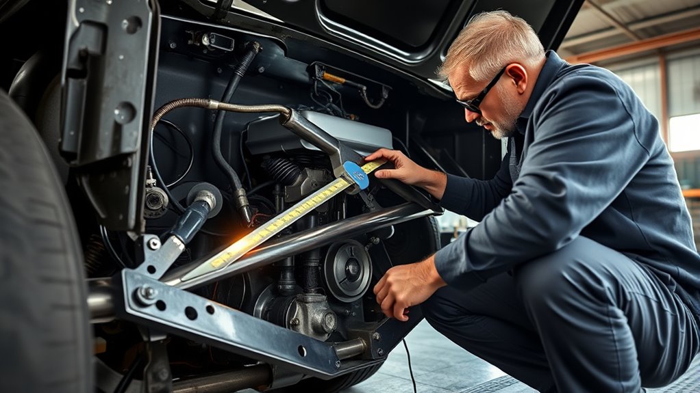
Before you weld the crossmember, check that the engine bay has room for the engine, transmission, steering, exhaust, oil pan, radiator, accessories, hood, and future service work. Inspect the bay from above, below, and both sides while the drivetrain is held at its intended ride angle and position.
Mock up the engine and transmission as a unit before finalizing the crossmember. A physical test fit reveals contact points that measurements alone can miss. Include the actual mounts or representative isolators, accessory drives, headers or manifolds, steering shaft, rack or box, oil filter, starter, and planned exhaust route.
Keep checking alignment as you work. A small shift can change fan clearance, shifter position, driveshaft angle, exhaust routing, axle or CV-joint angles, and service access. Measurements support the mockup, but they do not replace it.
- Check oil pan-to-crossmember clearance through normal engine movement.
- Check the steering shaft, rack, or box through full lock-to-lock travel.
- Check header, manifold, downpipe, and heat-shield clearance.
- Check firewall, transmission tunnel, shifter, and driveshaft position.
- Check radiator, fan, belts, pulleys, hoses, and hood clearance.
- Check whether filters, drain plugs, starter fasteners, and mount bolts remain serviceable.
If a part crowds the area, rework the layout before cutting or final welding. Forcing the drivetrain into a tight opening can cause contact, vibration, excess heat, cracked mounts, or difficult future repairs. Review basic process control and flux-core welding fundamentals before using any unfamiliar process on fabrication work.
Make the Job Safe Before You Cut
Set up the project as vehicle hot work. Welding and grinding can send sparks into hidden cavities, carpet, insulation, seam sealer, undercoating, wire loom, rubber hose, and oily areas. OSHA’s general welding and cutting requirements call for movable fire hazards to be removed, immovable hazards to be shielded, suitable extinguishing equipment to be ready, and a fire watch when conditions could allow more than a minor fire.
Support the vehicle on a rated lift or rated stands placed under sound structure. Level it at the manufacturer’s datum points when the measurement procedure requires that. Never rely on a hydraulic jack while cutting, bracing, welding, or working under the vehicle.
- Brace or fixture the chassis before removing a member that may hold the structure in position.
- Remove fuel, brake, electrical, rubber, trim, carpet, insulation, and sound-deadening parts from the heat and spark path when practical.
- Shield components that cannot be removed with suitable fire-resistant barriers.
- Inspect both sides of every panel and inside nearby cavities before, during, and after hot work.
- Keep an appropriate, charged fire extinguisher within immediate reach.
- Use a trained helper as a fire watch when sparks or conducted heat can reach hidden combustibles.
- Continue the fire watch for at least 30 minutes after welding or cutting, and longer if the area can conceal smoldering material.
Note: Do not weld near fuel vapor, a leaking fuel system, an unprepared tank, or any explosive atmosphere. If you cannot remove or effectively protect the hazard, stop. OSHA prohibits welding when required fire-safety controls cannot be met.
Protect Electrical, SRS, and Hybrid Systems
Follow the vehicle maker’s shutdown procedure before welding. Disconnecting the 12-volt battery may be only one step. Some vehicles require wait times, module disconnection, retained-power discharge, air-bag precautions, or high-voltage disablement. Electric and hybrid vehicles require trained personnel and model-specific high-voltage procedures.
Place the welding work clamp on clean metal as close to the weld as practical, with the current path away from bearings, hinges, steering joints, wiring, modules, and ground straps. Remove sensitive electronics from the repair area when the service information requires it. After reassembly, complete any required scan, initialization, steering-angle reset, or calibration.
Control Welding Fumes and Coating Hazards
Clean coatings from the weld zone and use general ventilation or local exhaust that draws fumes away from your breathing zone. OSHA’s welding-fume guidance recommends understanding the material, removing coatings that can create toxic exposure, keeping your head out of the plume, and using respiratory protection when ventilation and work practices do not control exposure. Review this garage ventilation setup guide for practical airflow planning.
Check labels and safety data sheets before using cleaners, primers, coatings, or seam sealers. Do not weld until cleaners have been removed and the surface is fully dry. Never assume an unknown coating or solvent residue is safe to heat.
Measure Engine and Transmission Mount Space
Build a reference sheet before cutting. Record the vehicle’s approved datum dimensions, crossmember position, frame-rail spacing, mount centerlines, engine angle, transmission output position, ride height, and clearances. Photograph the setup and mark fixed reference points that will remain after the original part is removed.
Use a level, straightedge, plumb bob, tram gauge, angle finder, or chassis measuring system as the job requires. Compare left-to-right dimensions and diagonals, but do not rely on diagonals alone when the service manual provides dedicated control points.
Measure Mount Clearance
Measure vertical, horizontal, and fore-aft distances from stable chassis references to the planned engine and transmission mount points. Include the thickness and compressed height of the actual isolators, not just the bare bracket locations.
- Check header and exhaust room.
- Confirm transmission tunnel and shifter space.
- Mark bracket, bolt, socket, and tool-access paths.
- Check oil pan, steering, axle, and suspension clearance.
- Build a cardboard, wood, or light-gauge prototype before cutting structural steel.
- Record the planned driveline angle and output-shaft centerline.
This layout gives you a repeatable target for each test fit and reduces unnecessary cutting, grinding, and rework.
Adjust Mount Position
Keep paired mounts square to the drivetrain and symmetrical to the chassis unless the vehicle design specifies an offset. Account for engine tilt, oil-pan shape, transmission angle, axle or driveshaft alignment, and the movement allowed by the isolators.
Refine prototype tabs and pads until the drivetrain rests in position without being forced. Confirm that mount bolts can be installed and removed, that brackets do not load the isolators sideways, and that normal powertrain movement will not cause contact.
Pro Tip: Make a written measurement sheet and keep one fixed reference on each side of the vehicle. Recheck those points after every major cut and tack. A dimension that starts moving is an early warning that the chassis or fixture is not holding position.
Choose the Right Material, Joint, and Welding Process
Select material from the vehicle-specific procedure or from an engineered fabrication design. Do not choose steel only by matching visible thickness. Grade, yield strength, heat treatment, shape, section modulus, bend radius, joint location, and corrosion coating can all affect the final load path.
MIG or MAG welding is common for approved automotive steel repairs and mild-steel fabrication, while TIG can offer precise heat and puddle control on suitable materials. Flux-cored welding may be appropriate for some fabricated mild-steel parts, but it creates slag and spatter and is not a universal substitute for the process specified by the manufacturer or engineer. Do not assume a process works on every metal; this guide on aluminum and flux-core limitations explains one common compatibility mistake.
The correct process depends on the base material, thickness, access, joint design, required weld type, filler metal, shielding gas, machine capability, and welder qualification. Structural automotive work may also specify squeeze-type resistance spot welds, plug welds, MIG brazing, rivet bonding, or another attachment method instead of a continuous arc weld.
Pro Tip: Before welding the vehicle, make test coupons from the same type and thickness of material with the same joint, access, machine, wire, gas, and settings. Destructively test the coupons or use the qualification method required by the repair procedure.
Use clean, straight material without deep rust, cracks, laminations, or unknown previous repairs. Add gussets, sleeves, fish plates, or boxed reinforcements only when the approved design calls for them. Random reinforcement can move stress into a weaker area, trap moisture, or block steering, exhaust, suspension, or service access.
Products Worth Considering

ER308L WIRE: A low-carbon stainless steel wire engineered to minimize intergranular carbide precipitation. This enhances corrosion resistance without the need for stabilizers, making it ideal for critical applications.

Lincoln ED030584 .035", NR-211, LB Spool, Inner Shield Flux-Core Welding Wire

Commonly used for general shop applications with poor fit-up
Get the Engine Bay Ready for Welding
Remove anything that blocks safe access, accurate measurement, torch angle, inspection, or fire control. Depending on the job, this may include the engine, transmission, radiator, mounts, accessories, hoses, wiring, steering parts, brake or fuel lines, heat shields, trim, carpet, insulation, and seam sealer.
Label hoses, wiring, brackets, shims, and fasteners as you remove them. Store sensitive parts away from grinding dust and weld spatter. Keep the bay open enough to inspect the front and back of every joint.
- Strip interference from the weld and spark zones.
- Tag electrical leads, hoses, lines, shims, and ground straps.
- Move or shield fuel lines, brake lines, wiring, rubber, glass, and painted panels.
- Remove dirt, grease, paint, rust, undercoating, seam sealer, and plating from the weld area.
- Use ventilation or local exhaust without blowing shielding gas away from the arc.
Products Worth Considering
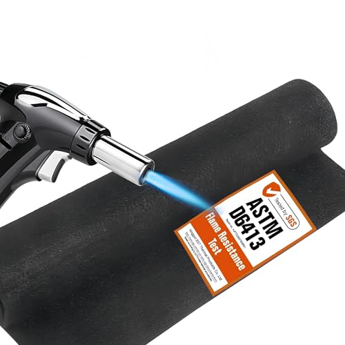
🔥The BSTFLEX Welding Blanket fireproof cloth, certified to ASTM D6413, high Quality Welding Blanket: Made of heat-resistant carbon fiber with thermal conductivity of 0.13 W/(m-K), the fireproof welding blanket can withstand temperatures as high as 3000° F(1648°C), providing maximum thermal protection for most welding operations.

Premium side split rust leather
Premium side split rust leather
Prepare the Weld Surfaces
Cut the original member only after the vehicle is supported, braced, measured, and marked. Trim to the approved joint or sectioning location. Remove damaged or heat-affected metal as directed, then shape the opening so the replacement fits without being forced.
Clean each joint to sound bare metal. Grind rough edges, remove burrs, and prepare the specified bevel, overlap, flange, sleeve, or plug-weld holes. Good mild-steel cleaning and preparation helps reduce contamination, but the vehicle procedure still controls how coatings and flanges must be prepared.
Check fit-up before tacking. Gaps, poor access, mismatched thickness, and hidden contamination can lead to lack of fusion, undercut, porosity, burn-through, or missed sections. If you cannot see the puddle, maintain the required gun angle, or inspect the completed joint, revise the plan.
Cut, Tack, and Test-Fit the Crossmember
Cut the replacement material only after the prototype and reference measurements are confirmed. Shape it for required clearance without creating abrupt notches, sharp internal corners, thin transitions, or unsupported openings that concentrate stress.
Clamp the crossmember in its fixture or final position, then place enough tacks to hold it securely. Use a balanced tack sequence so the part does not walk or twist. After the first tacks, stop and recheck the chassis reference points, diagonals, crossmember height, mount centerlines, and level.
- Confirm mount locations after each tack group.
- Check that the replacement sits against every mating surface as designed.
- Compare the left and right control points, not only the visible edges.
- Verify that the opening remains level and the chassis remains supported.
- Inspect the back of each tack for heat damage, fire, and access problems.
Test-Fit Before Final Welding
Install or lower the engine and transmission into the bay while the crossmember and mount brackets are still only tacked. Position the drivetrain as one assembly and confirm firewall, tunnel, steering, oil-pan, exhaust, radiator, hood, shifter, driveshaft, axle, and service clearances.
Final welding comes after the drivetrain mockup, not before it. Tack, measure, test-fit, adjust, and only then lock the structure in place.
Cycle the steering from lock to lock. Check the suspension or axle through the movement that can affect the crossmember. Confirm that flexible mounts have enough room for torque movement and that hoses, wiring, heat shields, and fasteners can still be installed.
If anything binds or sits at the wrong angle, cut or move the tacks and correct the layout. Do not pull mount holes into position with bolts or use drivetrain weight to force a misaligned bracket into place.
Complete the Welds With Controlled Heat
Remove the drivetrain if it blocks safe access or exposes fuel, wiring, electronics, rubber, or finished parts to heat and spatter. Reconfirm every reference dimension before final welding.
Use the approved weld type, length, spacing, sequence, process, filler metal, shielding gas, and settings. Keep the work clamp close to the joint. Use a balanced sequence and allow controlled cooling where needed to limit distortion. Do not quench a structural weld unless the approved procedure specifically requires it.
Preheat only when the identified material, thickness, filler system, or welding procedure calls for it. Unknown or high-strength material is not a reason to guess at preheat. Excess heat can change material properties and damage coatings or nearby parts.
After each weld group, remove slag when applicable and inspect for cracks, crater defects, porosity, undercut, overlap, lack of fusion, missed edges, burn-through, and distortion. Do not grind a structural weld flush unless the procedure allows it. Grinding can hide defects or reduce the required weld size.
- Mount holes align without prying or pulling.
- Control-point dimensions return to the recorded values.
- Weld toes tie into both pieces without visible undercut or overlap.
- No visible cracks, pinholes, crater cracks, or porous areas remain.
- Reinforcement does not block steering, suspension, exhaust, cooling, or service access.
- The back side of the repair is complete, clean, and ready for corrosion protection.
Use the required weld size and length for the joint, material, and load path. A visible bead alone does not prove that the design, penetration, or heat input is correct.
A crossmember can look finished and still be unsafe. Correct material, approved joints, stable dimensions, sound welds, controlled heat, and full clearance all matter.
Inspect the Repair Before Paint
Complete the inspection before coatings hide the joint. Use bright light, mirrors, and access to both sides. A qualified inspector should compare the repair with the approved procedure and the recorded chassis dimensions.
Visual inspection is the minimum. Depending on the design, material, weld procedure, and local requirements, the job may also call for dye penetrant, magnetic-particle inspection, ultrasonic testing, destructive coupon results, alignment-bench measurements, or an engineering sign-off. Choose the method that can detect the expected defect in the material being inspected.
Do not accept a repair with cracks, incomplete joints, unexplained distortion, forced mount alignment, or dimensions outside the allowed tolerance. Correct the cause rather than covering it with extra weld or a random plate.
Prime and Paint Bare Metal
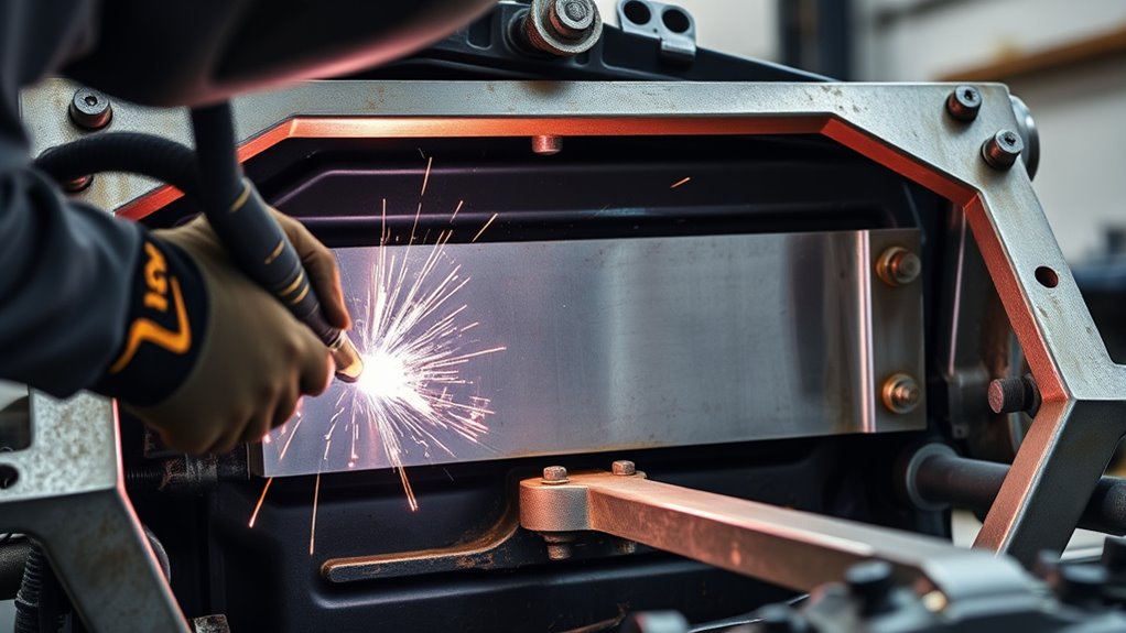
After the welds and dimensions pass inspection, clean grinding dust, residue, oil, and loose contamination from every exposed surface. Use only cleaners approved for the coating system, then remove all residue and allow the metal to dry fully before primer.
Restore each coating the vehicle or paint system requires. That may include weld-through primer on prepared flanges before assembly, epoxy or direct-to-metal primer on exposed steel, seam sealer at specified joints, cavity wax inside boxed sections, and a durable topcoat or chassis coating.
- Follow the coating maker’s surface-preparation and flash-time instructions.
- Cover edges, weld toes, plug-weld areas, seams, and the back of the repair.
- Keep drain holes and designed ventilation paths open.
- Apply seam sealer only where the approved repair procedure calls for it.
- Allow primer, sealer, and topcoat to cure before assembly or road exposure.
Use a rust-resistant system that tolerates engine-bay heat, moisture, road debris, and vibration. Thin, even coats reduce runs and help the coating cure correctly. Clean metal also reduces contamination that can contribute to weld porosity and process problems.
Install and Verify the Engine and Transmission Mounts
Once the crossmember has passed inspection and the required coatings have cured, install the engine and transmission with the final mounts, isolators, spacers, brackets, and hardware. Position the engine and gearbox as a unit so the measurements reflect the complete drivetrain.
Verify the firewall, tunnel, steering, exhaust, oil pan, radiator, hood, driveshaft, axle, and service clearances with the final hardware installed.
Torque fasteners to the specification for the exact mount and hardware. Do not reuse one-time-use fasteners. Confirm driveline angle, shifter reach, output-shaft centerline, mount-pad height, and isolator position.
Check the drivetrain through the movement allowed by its mounts. Look for contact at the crossmember, steering, exhaust, body, fan, hoses, and wiring. Wear suitable eye, face, hand, skin, hearing, and respiratory protection during any remaining cutting or grinding. This PPE setup checklist covers basic shop protection.
Complete the Final Inspection and Controlled Road Test
Do not start or drive the vehicle until the structural inspection, fastener torque, fire check, fluid-line inspection, steering check, and any required alignment, scan, reset, or calibration are complete.
- Confirm the engine and transmission mounts are seated and torqued.
- Verify the steering moves freely from lock to lock without contact.
- Check brake lines, fuel lines, hoses, wiring, grounds, and heat shields for damage.
- Check that the engine, exhaust, driveshaft, and axles have room to move.
- Look for fresh paint marks that reveal contact.
- Complete any required wheel alignment and steering-angle or driver-assistance calibration.
- Perform pre- and post-repair diagnostic scans when the vehicle maker requires them.
Start the engine while the vehicle remains stationary and watch for vibration, fluid leaks, electrical faults, abnormal movement, or contact. If the static check passes, perform the first low-speed drive in a controlled area. Stop immediately for clunks, scraping, steering change, driveline shake, warning lights, or unusual vibration.
After the first heat cycle and short drive, reinspect the crossmember, welds, mounts, fasteners, adjacent lines, coatings, and contact points. Follow the approved procedure for any scheduled reinspection or torque check.
Note: Road-use rules vary by location and vehicle class. For U.S. commercial motor vehicles, 49 CFR 393.201 requires frame welding and welded frame repairs to follow the vehicle manufacturer’s recommendations, and FMCSA treats crossmembers as part of the frame. Check the rules that apply to your vehicle, inspection program, insurance, and intended use.
Frequently Asked Questions
Can a crossmember be welded?
Yes, some crossmembers can be welded or replaced by welding, but only when the material, joint location, attachment method, heat limits, fit-up, and inspection follow the vehicle maker’s procedure or an engineered fabrication design. Some parts must be replaced at factory seams or attached by another approved method.
Will J-B Weld hold up to engine heat?
J-B Weld Original is rated by its manufacturer for temperatures up to 550°F after full cure. That temperature rating does not make epoxy a substitute for an approved structural weld, bracket, fastener, or crossmember. Use it only for suitable non-structural repairs.
What is the best welder for car frame repair?
There is no universal best welder. The correct equipment and process come from the vehicle-specific procedure or engineered design. Approved repairs may use GMAW/MAG, resistance spot welding, MIG brazing, TIG, rivet bonding, or another method, depending on the material and joint.
Is it illegal to weld a vehicle frame?
Not everywhere and not in every situation. Legality depends on the country, state or province, vehicle class, road-use status, inspection rules, and manufacturer requirements. Commercial vehicles can face specific rules. Check the applicable law and inspection standard before modifying or driving the vehicle.
Can I weld a crossmember with the engine still in the bay?
The drivetrain may need to stay in place for mockup and tacking, but final welding is often safer with it removed. You need full access, a safe current path, fume control, and protection for fuel parts, wiring, electronics, rubber, paint, and finished components. Follow the model-specific procedure.
Should I fully weld the mounts before test-fitting the drivetrain?
No. Tack the crossmember and mount brackets, test-fit the engine and transmission together, and verify all dimensions and clearances. Fully weld only after the drivetrain sits correctly, the mounts are not forced, and the steering, exhaust, oil pan, driveshaft, axles, cooling parts, and service points all clear.
What signs mean the crossmember weld is unsafe?
Warning signs include cracks, crater defects, porosity, undercut, overlap, lack of fusion, burn-through, incomplete joints, heavy distortion, dimensions outside tolerance, mount holes that need force to align, or contact during drivetrain, steering, or suspension movement. Stop and have the repair inspected.
Do I need an alignment after crossmember welding?
You need an alignment check whenever the crossmember locates suspension or steering parts, or whenever the repair could change chassis geometry. Some vehicles also require a steering-angle reset or driver-assistance calibration after alignment. Follow the service manual.
Can I grind the crossmember welds smooth?
Only when the approved procedure allows it. Grinding can reduce weld size, remove sound metal, or hide defects. Inspect the weld first, then grind only the amount and areas permitted by the repair or fabrication plan.
Conclusion
Welding an engine bay crossmember starts with repair information, measurement, bracing, and a complete drivetrain mockup. It does not start with the cut-off wheel. Identify the material and load path, protect the vehicle from fire, fumes, and electrical damage, tack and test-fit before final welding, then inspect the structure before paint hides the joints. Do not return the vehicle to the road until alignment, steering, fasteners, clearances, scans, calibrations, and any required professional or legal checks are complete.
Sources
- OSHA 29 CFR 1910.252, General Requirements for Welding, Cutting, and Brazing: fire-hazard removal, shielding, extinguishing equipment, fire-watch conditions, and post-work fire watch.
- OSHA Fact Sheet: Controlling Hazardous Fume and Gases During Welding: coating removal, plume avoidance, ventilation, local exhaust, and respiratory protection.
- I-CAR OEM Technical Information Matrix: vehicle-specific material, sectioning, attachment, weld-through primer, and corrosion-protection information.
- Nissan Collision Repair Position Statements: examples of OEM structural measurement, body-manual, welding, electronics, and corrosion-protection requirements.
- 49 CFR 393.201, Frames: U.S. commercial-vehicle requirements for frame modifications and welded repairs.
- J-B Weld Original Twin Tube Specifications: manufacturer temperature, cure, and product-use information.




