
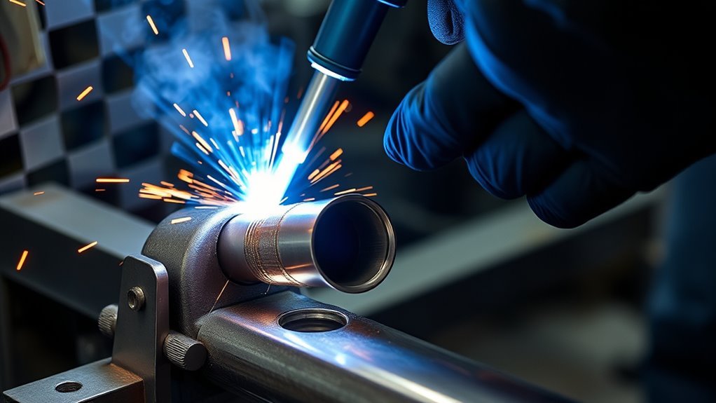
A poor oxygen sensor bung installation can cause exhaust leaks, false readings, damaged threads, and early sensor failure. A reliable installation starts with the correct weld-in bung, a sound section of pipe, safe sensor placement, and careful heat control. The steps below show you how to drill, tack, weld, test, and finish an O2 sensor bung without damaging the exhaust or sensor.
Quick Answer
Use a purpose-made weld-in bung that matches the sensor thread and exhaust material. Mount it on the upper half of the pipe with the connector above the sensor tip. Measure the bung before drilling, clean both parts to bare metal, tack it square, and seal it with short, controlled welds. Leak-test and clean the threads before installing the sensor.
Key Takeaways
- Confirm the sensor thread before buying the bung. M18x1.5 is common, but it is not universal.
- Place the sensor on the upper arc of the pipe, with its connector above the sensing tip, and follow the sensor manufacturer’s angle requirements.
- Measure the bung’s locating neck instead of assuming every bung needs a 3/4-inch hole.
- Keep the oxygen sensor out of the bung until welding, cooling, testing, thread cleaning, and coating are complete.
- Use short weld segments and allow cooling time so thin exhaust tubing does not burn through.
- Prefer a smoke test over pressurizing the exhaust with unregulated compressed air.
At a Glance
| Time Required | About 60 to 120 minutes for a clean, removable pipe; longer when rust, poor access, or vehicle disassembly is involved |
| Difficulty | Intermediate; you should already be able to control a weld puddle on thin tubing |
| Tools Needed | Center punch, drill, step drill, deburring tool, grinder, metal clamps, MIG or TIG welder, thread chaser, and smoke-testing equipment |
| Cost | Depends on the bung, drill bits, filler wire, shielding gas, coating, pipe condition, and whether a shop must remove the exhaust |
What’s in This Article
- Choose the Right O2 Sensor Bung
- What You’ll Need Before You Start
- Decide Whether to Remove the Exhaust
- Mark the Exhaust Pipe for the Bung
- Drill the Bung Hole Cleanly
- Clean the Pipe and Bung Before Welding
- Choose the Best Welding Process
- Set MIG Welder Settings for Thin Pipe
- Tack Weld the O2 Bung in Place
- Finish the Weld Without Leaks
- Place the O2 Sensor in the Dry Zone
- Check for Leaks and Weld Spatter
- Install the O2 Sensor
- Clean Up and Protect the Weld
- Common Mistakes That Ruin O2 Bung Installs
- Troubleshoot O2 Bung Welding Problems
- Frequently Asked Questions
- Conclusion
- Sources
Choose the Right O2 Sensor Bung
Start with a purpose-made weld-in oxygen sensor bung. Check the thread on the actual sensor or its installation manual before ordering the bung. Many Bosch and aftermarket wideband sensors use M18x1.5 threads, but smaller and application-specific sensors also exist.
Match the bung material to the pipe whenever possible:
- Use a mild-steel bung on mild-steel or aluminized mild-steel tubing.
- Use a stainless-steel bung on stainless exhaust tubing.
- Use the filler metal recommended for the base metals and welding process.
Matching materials makes the weld easier to control and reduces corrosion and cracking concerns. Welding a stainless bung to mild steel is possible with the correct filler and technique, but it is not the easiest choice for a beginner.
Choose a bung with a wide, weldable flange or locating neck that sits securely on the pipe. Do not rely on a universal thickness or grind the bung shorter unless its manufacturer specifically allows it. The bung controls the sensor’s depth, thread engagement, and exposure to the exhaust stream.
Check the thread, material, flange shape, and sensor depth before drilling. The correct bung matters more than a generic hole-size rule.
Buy the bung from the sensor manufacturer, exhaust manufacturer, or a reputable automotive supplier. Accurate machining helps the sensor start straight and seal correctly. Good part selection also reduces unnecessary fitting and can help you avoid extensive rust-removal work later.
Products Worth Considering

304 Stainless Steel Construction: Crafted from high-quality 304 stainless steel for exceptional corrosion resistance and long-lasting durability in any environment
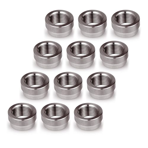
304 Stainless Steel Construction: Crafted from high-quality 304 stainless steel for exceptional corrosion resistance and long-lasting durability in any environment

304 Stainless Steel Construction: Crafted from high-quality 304 stainless steel for exceptional corrosion resistance and long-lasting durability in any environment
What You’ll Need Before You Start
Gather the layout, drilling, welding, safety, and testing equipment before opening the pipe. A clean pipe on a workbench may take about an hour. A rusty system or an installation under the vehicle can take much longer.
- Weld-in oxygen sensor bung that matches the sensor and exhaust material
- Sensor installation instructions or controller manual
- Center punch and small pilot or center drill
- Step drill or correctly sized hole cutter
- Drill, cutting fluid, and deburring tool
- Calipers or a ruler for measuring the bung’s locating neck
- Angle grinder, abrasive pad, wire brush, and suitable degreaser
- MIG or TIG welder suitable for thin tubing
- Correct filler wire, shielding gas, contact tip, and polarity
- Metal clamps, locking pliers, or a purpose-made bung fixture
- M18x1.5 thread chaser or the correct chaser for your sensor
- Automotive smoke machine or another controlled exhaust leak tester
- High-temperature coating for exposed mild steel
- Welding helmet, safety glasses, gloves, hearing protection, and flame-resistant clothing
- Fire extinguisher, welding blanket, and adequate ventilation
Warning: Do not weld near leaking fuel, fuel vapors, brake cleaner residue, undercoating, carpet, wiring, fuel lines, brake lines, batteries, or other combustible material. Wear proper flame-resistant welding clothing, keep an extinguisher ready, and provide ventilation that removes fumes from your breathing zone.
Inspect the pipe before doing any layout work. If rust has thinned the wall, the pipe flakes under a wire brush, or a screwdriver easily punctures the area, replace that exhaust section instead of welding a new bung into weak metal.
Products Worth Considering

【Easy to Weld in Bung】: Designed specifically for 1.5–2 inch exhaust pipes, this bung matches the pipe curvature more precisely than universal bungs, ensuring better fit and cleaner welds
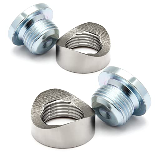
Notched style mounting bung was made of 304 stainless steel easy to weld .

Universal Compatibility:M18x1.5 threads fit all standard O2 sensors (Bosch/Denso/NTK/OEM) for secure installation on exhaust systems
Decide Whether to Remove the Exhaust
Removing the pipe usually gives you the safest access, the best drilling angle, better chip control, and a more comfortable welding position. It also lets you inspect and deburr the inside of the hole before welding.
Welding with the exhaust on the vehicle may be reasonable when the pipe is solid and you have clear access to every side of the weld. Before doing so:
- Let the vehicle and exhaust cool completely.
- Inspect above, behind, and on the opposite side of the pipe.
- Move or shield wiring, hoses, heat-sensitive panels, carpet, undercoating, and fuel-system parts.
- Follow the vehicle manufacturer’s battery, module, restraint-system, and welding procedures.
- For a hybrid or electric vehicle, follow the manufacturer’s high-voltage disabling procedure. Do not work on a high-voltage system without the required training.
- Place the welder work clamp on clean metal on the same exhaust section, as close to the weld as practical.
- Keep the current path away from bearings, wiring grounds, control modules, and other components.
- Keep an extinguisher ready and use a second person as a fire watch when sparks can enter hidden areas.
- Inspect the area for heat or smoldering material for at least 30 minutes after welding when fire-watch conditions apply.
Vehicle body-builder guidance recommends disconnecting battery negative cables before welding and placing the work clamp close to the weld. The exact procedure still depends on the vehicle, so check its service information before disconnecting or reconnecting anything.
Note: Adding a separate wideband bung must not remove, relocate, bypass, or disable a required factory oxygen sensor or catalytic converter. Keep the vehicle’s certified emissions equipment functional and follow the laws that apply where the vehicle is used.
Mark the Exhaust Pipe for the Bung
Choose the sensor location before drilling. The correct point depends on whether you are replacing a factory sensor or adding a separate wideband sensor.
For a Factory Replacement Sensor
Keep the bung in the factory-specified location and orientation. Moving an upstream or downstream factory sensor can change warm-up behavior, exhaust sampling, catalyst monitoring, wiring reach, and emissions-system operation.
For an Added Wideband Sensor
Use the sensor or controller manufacturer’s installation instructions. A combined reading is often taken after a collector, while separate bank readings require separate locations. Keep the sensor away from the tailpipe outlet, because outside air can affect the reading. Repair any leak upstream of the sensor before relying on its output.
On turbocharged engines, sensor distance and exhaust-temperature limits vary significantly. Do not use a generic distance from the turbine or exhaust port. Follow the sensor manufacturer’s temperature and location limits.
Check all of the following before marking:
- The sensor will sit on the upper half of the pipe.
- The connector and wire will remain above the sensing tip.
- A wrench and the sensor body will clear the floor, frame, heat shields, driveshaft, suspension, and nearby pipes.
- The sensor will not be the lowest part of the exhaust or exposed to road impact.
- The harness can reach without touching the exhaust or being stretched.
- The location is not directly on a tight bend or welded seam unless the manufacturer approves it.
Use a marker and center punch at the final drilling point. Review thin automotive metal welding techniques before welding if you have not practiced heat control on exhaust tubing.
Mark once, confirm the angle and clearance twice, and drill only after the sensor can be installed and removed without interference.
Drill the Bung Hole Cleanly
Do not choose the hole size from the sensor’s M18 thread alone. Measure the outside diameter of the bung’s locating neck or follow the bung drawing. The goal is a close fit that lets the flange sit flat without leaving a large gap for the weld to bridge.
- Remove the pipe and place it securely on a bench whenever practical.
- Center-punch the drilling point.
- Start a small, straight pilot hole.
- Open the hole gradually with a step drill or correctly sized cutter.
- Stop often and test the bung fit.
- Deburr both sides of the opening.
- Remove every chip from inside the exhaust before welding.
| Tool | Purpose | Correct Result |
|---|---|---|
| Center punch | Locks the drilling point | The pilot bit does not wander |
| Pilot or center drill | Starts the opening | A centered, controlled pilot hole |
| Step drill | Enlarges the opening gradually | The bung neck fits with minimal gap |
| Deburring tool | Removes sharp edges and loose metal | The bung sits flat and no burr enters the exhaust |
Run the drill slowly enough to maintain control. Use suitable cutting fluid when required by the pipe and tool. Keep the bit square to the local pipe surface and do not force it.
Before using a grinder, confirm that the wheel is suitable for the material and that its speed rating meets or exceeds the grinder’s speed. This angle grinder wheel and safety guide explains the basic checks.
Warning: Do not leave drilling chips inside the exhaust. Chips can rattle, damage downstream components, contaminate a catalyst, or be blown from an open pipe during testing.
Clean the Pipe and Bung Before Welding
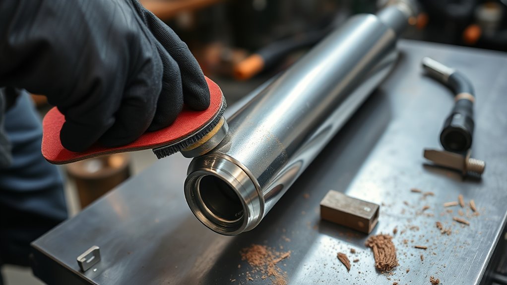
Clean metal gives you a steadier arc, better fusion, and fewer pinholes. Degrease first so the grinder does not smear oil across the weld zone.
- Remove oil, grease, road dirt, and adhesive residue with a suitable cleaner.
- Grind or abrade paint, aluminized coating, scale, and corrosion from the full weld area.
- Clean beyond the edge of the planned weld so the arc never reaches coating.
- Clean the bung’s flange and outside edge to bare metal.
- Wipe away dust and let all cleaner evaporate before welding.
Do not weld over rust, paint, oil, exhaust sealant, undercoating, or plating. If the pipe is zinc-coated or has zinc-bearing material, remove the coating from the heat zone and provide effective ventilation. Review how to remove zinc coating before welding and the precautions for MIG welding coated steel.
Use a dedicated stainless-steel brush on stainless tubing so a carbon-steel brush does not embed contamination. Replace the pipe section if cleaning reveals deep pits, cracks, or paper-thin metal.
Choose the Best Welding Process
MIG and TIG can both produce a sealed O2 bung weld. The better process depends on the pipe material, wall thickness, access, machine, and your skill.
| Process | Advantages | Limitations |
|---|---|---|
| MIG with solid wire | Fast, widely available, and easy to tack in short bursts | Requires clean metal, shielding gas, and careful heat control |
| TIG | Excellent puddle and heat control; especially useful on stainless | Slower and requires more skill and access |
| Self-shielded flux-core | No shielding-gas bottle and better tolerance of outdoor air movement | Often runs hotter, creates slag and spatter, and is harder to control on thin exhaust tubing |
Solid-wire MIG or TIG is usually easier to keep clean and controlled on thin exhaust tubing. Flux-core can work on sound mild steel when the machine and wire support thin material, but practice first and remove all slag between weld segments. These flux-core welding tips cover polarity, travel angle, and slag control.
Set MIG Welder Settings for Thin Pipe
Do not rely on one voltage and wire-feed setting for every exhaust pipe. Wall thickness, bung mass, wire diameter, shielding gas, joint fit, machine design, input voltage, and welding position all affect the result.
Use this setup sequence:
- Measure or identify the pipe wall thickness.
- Use the parameter chart inside the welder or its official manual.
- Select a wire size the machine recommends for that thickness.
- Confirm polarity for the exact wire.
- Set shielding-gas flow according to the welder and gas supplier’s guidance.
- Make test tacks and short welds on scrap tubing of the same material and thickness.
- Adjust until the bead ties into both pieces without excessive buildup, spatter, or burn-through.
For mild-steel exhaust tubing, ER70S-6 solid wire is a common choice. A .023- or .024-inch wire can offer easier low-current control on thin tubing, while .030-inch wire may suit thicker tubing or machines designed around that size. Follow the welder’s chart instead of assuming one wire is correct for every job.
Keep the arc short and the gun steady. Watch the edge of the pipe more closely than the thick bung because the pipe will melt first. If the pipe edge disappears or the puddle sags, stop and allow the joint to cool.
Pro Tip: Drill a matching hole in a scrap piece of exhaust tubing and weld a spare washer or practice bung into it. A complete practice ring reveals heat, fit-up, and position problems before you touch the vehicle’s pipe.
Tack Weld the O2 Bung in Place
Remove the oxygen sensor before fitting or welding the bung. Do not use the sensor as an alignment tool or thread protector.
Place the bung over the hole and confirm that its flange sits flat. Hold it with a metal bung fixture, metal clamp, magnetic fixture suitable for the position, or locking pliers. Do not use a wood block, plastic tool, or other combustible support.
- Place the first short tack.
- Place the second tack directly opposite the first.
- Add a third and fourth tack at the remaining quarter points.
- Allow the joint to cool briefly.
- Check that the bung is still square and the flange remains seated.
- Confirm that the sensor will clear nearby parts at its final angle.
Opposing tacks limit movement as the metal contracts. If the bung pulls out of alignment, correct it before adding more weld. Do not try to force the sensor into a crooked bung later.
Finish the Weld Without Leaks
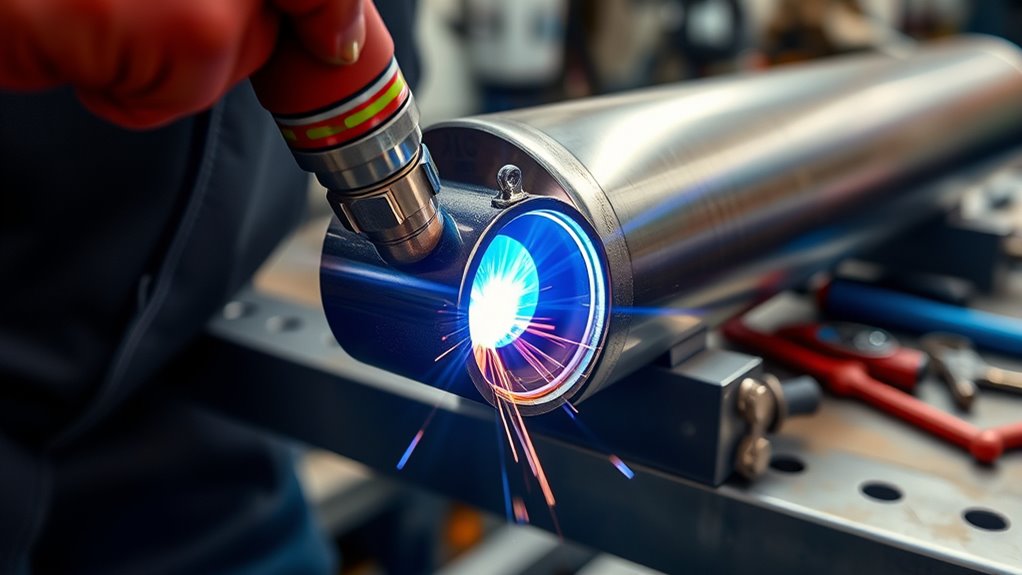
The joint needs a complete gas-tight seal, but thin tubing may not tolerate one slow continuous pass. Build the seal from short, overlapping weld segments.
- Weld a short section between two tacks.
- Move to the opposite side of the bung.
- Continue around the joint in alternating sections.
- Pause when the pipe begins to glow, sag, or lose a defined edge.
- Let the joint cool naturally between sections.
- Overlap the start and end of each section enough to avoid pinholes.
Avoid leaning the arc into the thin pipe. Direct more heat toward the heavier bung flange, then wash the puddle into the pipe edge. Do not build a large bead simply to hide poor fit-up.
| Check | Goal | Problem Sign |
|---|---|---|
| Fit-up | Flange sits flat with minimal gap | Large gap that requires excessive filler |
| Fusion | Bead ties smoothly into the bung and pipe | Cold lap, tall rope-like bead, or unfused edge |
| Heat control | Pipe keeps its shape | Sagging, glowing edge, or burn-through |
| Seal | No gaps or pinholes | Soot track, smoke escape, or bubbles during a controlled test |
Let the joint cool naturally. Quenching a hot bung with water can create rapid thermal contraction and may distort the joint.
Place the O2 Sensor in the Dry Zone
Condensation can damage a heated oxygen sensor, so the sensing tip should sit below the connector rather than trapping liquid inside the sensor housing. The safe general rule is to use the upper half of the pipe, from 9 o’clock through 12 o’clock to 3 o’clock, with the wire or connector pointing upward.
The exact angle depends on the sensor. AEM instructs users of its X-Series wideband system to mount the sensor more than 10 degrees above horizontal so condensation drains, while also advising against a completely vertical position for that system. Bosch advises installing its lambda sensors as close to vertical as possible with the wire upward. Follow the instructions supplied with your exact sensor and controller.
Dry-Zone Placement
Choose a section that remains above the exhaust’s low point. Do not install the bung on the bottom arc of the tube where water can collect after shutdown.
For an add-on wideband sensor, avoid the tailpipe outlet and repair leaks ahead of the sensor. Outside air or leak air can make the mixture appear leaner than it is. The sensor must also remain within its specified exhaust-gas and housing-temperature limits.
Avoid Moisture Exposure
Moisture exposure is controlled by both angle and location. A sensor mounted on the upper arc can drain toward the pipe, while one mounted below horizontal can hold condensation around the heated ceramic element.
- Keep the connector higher than the sensing tip.
- Avoid pipe low points and sections where water pools.
- Do not power a removable wideband sensor while it is lying in a wet or contaminated exhaust.
- Repair coolant, oil, or excessive-fuel problems that can contaminate the sensor.
Optimal Sensor Angle
Use the sensor manual’s diagram as the final authority. Before tacking, hold the sensor or a dimensionally accurate dummy tool above the bung without threading the real sensor into the weld area. Check:
- The required angle above horizontal
- Clearance for the sensor body and connector
- Room for a wrench or sensor socket
- Harness routing away from heat and moving parts
- Protection from road impact
Lock in the angle before final welding. A bung that is square to the pipe may still be wrong if the sensor points into a floor panel or leaves the connector below the sensing tip.
Check for Leaks and Weld Spatter
After the joint is fully cool, inspect the entire weld under bright light. Look for pinholes, cracks, undercut, unfused edges, slag, and soot-like contamination.
An automotive smoke machine is the preferred practical test because it can reveal small leaks without subjecting the exhaust to uncontrolled shop-air pressure. Follow the smoke machine’s instructions and test the system cold.
If a professional procedure uses regulated air and soap solution, use only minimal controlled pressure, secure every closure, stand clear of plugs, and wear eye protection. Never seal the exhaust and connect unregulated compressed air.
Mark any leak, grind only the defective area back to sound metal, clean it again, and re-weld it. Do not smear exhaust paste over a porous new bung weld as a substitute for proper fusion.
Inspect the threads for spatter after cooling. Use the correct thread chaser carefully and keep it square. A chaser cleans existing threads; it should not remove enough material to loosen the sensor fit. These welding-machine and weld-defect troubleshooting tips can help if porosity or unstable arc behavior continues.
Install the O2 Sensor
Install the sensor only after the weld has cooled, passed the leak test, and received any required coating.
- Confirm that the threads are clean and undamaged.
- Keep paint, grinding dust, oil, and anti-spatter compound out of the bung.
- Check the sensor’s sealing washer or sealing seat.
- Apply thread compound only when the sensor manufacturer calls for it. Many sensors arrive with the approved compound already applied.
- Never put grease, anti-seize, or cleaner on the sensing tip or through the sensor openings.
- Start the sensor by hand for several turns.
- Tighten it to the sensor manufacturer’s specified torque.
- Route the harness away from the pipe, driveshaft, suspension, sharp edges, and road debris.
- Reconnect electrical systems according to the vehicle manufacturer’s procedure.
Note: Do not use one universal oxygen-sensor torque value. Torque varies by sensor design, thread treatment, sealing method, and manufacturer.
Clean Up and Protect the Weld
Once the weld is sound and leak-free, remove loose soot, slag, and spatter. Do not grind the bead flat unless clearance requires it and enough sound weld will remain.
- Brush or lightly abrade the cooled weld.
- Inspect it again after cleaning.
- Degrease the surrounding pipe.
- Mask the bung opening, threads, and sealing face.
- Apply a compatible high-temperature coating to exposed mild steel.
- Allow the coating to cure as directed before running the engine.
Stainless tubing may not need paint, but it still needs cleaning and inspection. Never paint, wax, or coat the oxygen sensor itself. Bosch specifically warns against treating the sensor body and advises using only the recommended thread lubricant.
If cleaning exposes perforation or deep rust beside the new weld, stop and assess the damaged pipe. Paint cannot restore lost wall thickness or repair a porous weld.
Note: High-temperature paint protects clean mild steel from corrosion. It cannot seal pinholes, strengthen rust-thinned tubing, or correct a crooked bung.
Common Mistakes That Ruin O2 Bung Installs
- Drilling before checking sensor clearance and harness routing
- Mounting the sensor on the lower half of the pipe
- Assuming every bung requires a 3/4-inch opening
- Leaving drill chips or a sharp burr inside the exhaust
- Welding over rust, paint, aluminized coating, oil, or sealant
- Using a combustible wood block as a welding fixture
- Welding with the oxygen sensor installed
- Using one generic voltage setting without testing matching scrap
- Running one slow continuous pass and burning through the pipe
- Placing the work clamp far from an on-vehicle weld
- Skipping battery, module, or high-voltage precautions
- Using unregulated compressed air for leak testing
- Leaving weld spatter in the threads
- Forcing the sensor into crossed or distorted threads
- Painting the sensor, sealing face, or bung threads
- Relocating or disabling required emissions equipment
Correct these issues before installing the sensor. A few extra minutes spent on layout, cleaning, and testing can prevent false readings, exhaust leaks, damaged electronics, and a ruined sensor.
Troubleshoot O2 Bung Welding Problems
| Problem | Likely Cause | Fix |
|---|---|---|
| Pipe burns through | Too much heat, slow travel, large gap, or rust-thinned metal | Stop, cool the joint, reduce heat input, shorten welds, improve fit-up, or replace the weak pipe section |
| Porosity or pinholes | Oil, coating, rust, poor shielding gas, wind, or slag trapped between passes | Grind to clean metal, correct gas coverage, remove slag, and re-weld the affected area |
| Bung tilts after tacking | Tacks were placed on one side or the flange did not sit flat | Correct alignment before final welding and use opposing tacks |
| Sensor will not start by hand | Spatter, crossed threads, or heat distortion | Do not force it. Inspect the threads and use the correct chaser square to the bung |
| Sensor reads unexpectedly lean | Leak ahead of the sensor, location near the outlet, wiring problem, or incorrect controller setup | Smoke-test the exhaust, inspect wiring, verify the controller, and confirm the sensor location |
| Weld cracks after cooling | Material mismatch, contamination, excessive restraint, or poor fusion | Remove the cracked weld, confirm materials and filler, clean thoroughly, and re-weld with controlled heat |
Frequently Asked Questions
Can you weld an O2 sensor bung?
Yes. Use a purpose-made weld-in bung, match it to the sensor and pipe material, clean both parts to bare metal, keep the sensor out during welding, and control heat so the thin tubing does not burn through.
Will J-B Weld hold up on an exhaust bung?
Exhaust-specific patch products can be useful for some cracks or holes, but they are not equivalent to a fusion-welded threaded sensor mount. An oxygen sensor bung supports the sensor, seals exhaust pressure, and goes through repeated heat cycles, so welding is the proper permanent installation method.
What material should an O2 sensor bung be?
Match the pipe when practical. Use mild steel with mild-steel or aluminized mild-steel tubing and stainless steel with stainless tubing. Dissimilar materials may require a different filler and more advanced corrosion control.
How much does it cost to weld an O2 sensor bung?
There is no reliable universal price. A simple bench weld on a clean removable pipe costs less than a job that requires exhaust removal, rust repair, tight underbody access, stainless filler, electrical protection, or fabrication. Ask the shop whether its quote includes the bung, removal, welding, leak testing, coating, and reinstallation.
Can you weld an O2 bung with the exhaust on the car?
You can when access is safe and the vehicle manufacturer’s welding precautions are followed. Protect fuel and brake lines, wiring, modules, undercoating, carpet, and heat-sensitive parts. Follow battery and high-voltage procedures, place the work clamp close to the weld, keep an extinguisher ready, and inspect for smoldering material afterward. Removing the pipe is usually safer.
What size hole do you drill for an O2 bung?
Use the size specified by the bung manufacturer or measure the bung’s locating neck. Enlarge the opening gradually until the flange sits flat with minimal gap. Do not assume that every M18x1.5 bung needs the same hole.
What angle should an O2 sensor be mounted at?
Mount it on the upper half of the pipe with the connector above the sensing tip. Many aftermarket wideband instructions require the sensor to sit at least 10 degrees above horizontal, while some Bosch guidance favors a near-vertical wire-up position. Follow the manual for the exact sensor.
Should you disconnect the battery before welding an exhaust?
Follow the vehicle manufacturer’s welding and battery-disconnection procedure. Many vehicle and body-builder manuals call for disconnecting battery negative cables and placing the welder work clamp close to the weld. Hybrid and electric vehicles also require model-specific high-voltage precautions.
How tight should an O2 sensor be?
Use the torque specified for the exact sensor. Do not copy a torque from another sensor because thread coatings, sealing washers, sensor bodies, and manufacturer requirements vary. Start the sensor by hand and keep lubricant away from the sensing tip.
Conclusion
A dependable O2 sensor bung installation depends on correct placement, close hole fit, clean metal, controlled heat, sound vehicle-welding precautions, and a verified gas-tight seal. Keep the sensor out while welding, mount the bung on the pipe’s upper arc, and follow the sensor manufacturer’s angle and torque instructions. After the weld cools, smoke-test it, clean the threads, protect exposed mild steel, and route the sensor harness away from heat and moving parts.
Sources
- AEM X-Series UEGO Inline Instruction Manual — wideband sensor angle, condensation drainage, heat, and contamination guidance
- Bosch Motorsport Lambda Sensor LSU 4.9 — wire-up placement, leak control, outlet location, condensation, and thread-treatment guidance
- Miller MIG Welding Parameter Guide — wire-size ranges, setting selection, burn-through, porosity, and bead evaluation
- OSHA 29 CFR 1910.252, Welding, Cutting, and Brazing — combustible-material control, extinguishers, fire watches, ventilation, coatings, and pressure-test safety
- Vehicle Electrical and Welding Precautions — battery disconnection and close placement of the welder work clamp
- U.S. EPA Tampering and Aftermarket Defeat-Device Guidance — legal protection of required oxygen sensors and emissions-control equipment




