
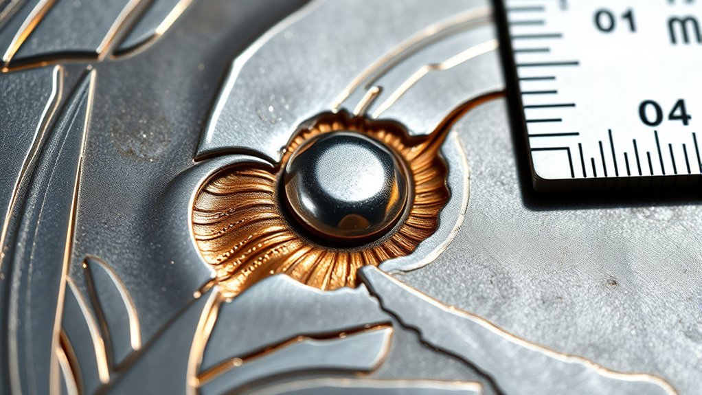
A weld macro test exposes a prepared cross-section of a weld so you can examine its shape, penetration, fusion boundaries, heat-affected zone, and visible discontinuities. The method is useful for procedure checks, welder training, production sampling, and failure investigation, but its findings apply only to the section that was cut and examined.
Quick Answer
A weld macro test is a destructive inspection of a weld cross-section. The sample is cut, ground or polished as required, etched with a material-specific reagent, and viewed by eye or at low magnification. It reveals weld geometry, penetration, fusion boundaries, the heat-affected zone, and visible discontinuities at that sampled location.
Key Takeaways
- A macro test examines one cut plane through a weld; it does not prove that the entire weld length is defect-free.
- Low-damage cutting, progressive grinding, cleaning, controlled etching, and good lighting are essential for a trustworthy result.
- The section may show penetration, weld profile, fusion boundaries, porosity, inclusions, cracks, undercut, and other discontinuities that intersect the prepared plane.
- The governing welding code, drawing, procedure, or project specification—not the photograph alone—sets the acceptance criteria.
- Etchants require a written procedure, a current Safety Data Sheet, compatible PPE, suitable local exhaust, and an approved waste plan.
At a Glance
| Time Required | About 45 minutes to several hours, depending on sample size, mounting, surface finish, etching, rework, and documentation |
| Difficulty | Intermediate to advanced; chemical etching should be performed by trained personnel under an approved procedure |
| Tools Needed | Low-damage cutting equipment, grinding and polishing supplies, cleaning materials, approved etchant, lighting or low-magnification optics, measuring tools, and task-specific PPE |
| Cost | Low when a shop already has suitable equipment; laboratory costs vary with sample preparation, measurements, photographs, and required reporting |
What’s in This Article
- What Is a Weld Macro Test?
- Which Standards and Acceptance Criteria Apply?
- Why Is Macro Testing Important for Weld Quality?
- How Is a Weld Macro Test Performed?
- How to Choose a Representative Weld Sample
- Key Equipment for Macro Testing
- What Common Defects Can Macro Etch Testing Reveal?
- How to Interpret Macro Etch Test Results
- How to Troubleshoot Preparation and Etching Problems
- How Weld Macro Testing Compares to Other Methods
- Essential Best Practices for Effective Macro Testing
- How to Apply Macro Test Findings
- What to Record After a Weld Macro Test
- Frequently Asked Questions
- Conclusion
- Sources
What Is a Weld Macro Test?
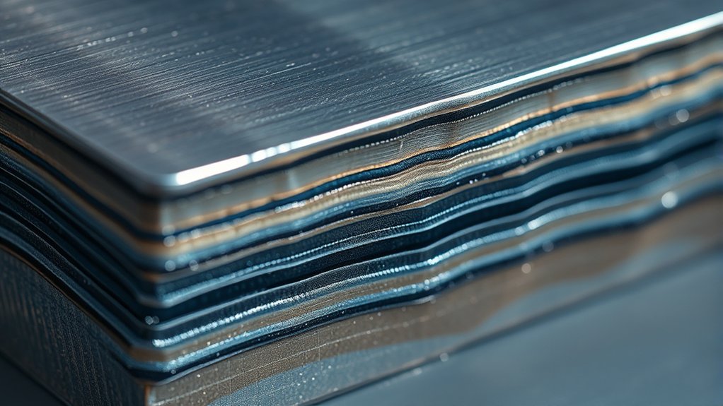
A weld macro test, also called a macro-etch examination, evaluates the large-scale features of a welded joint. A representative section is removed through the weld, prepared to a flat finish, and treated with a suitable etchant so the weld metal, fusion boundary, heat-affected zone, and base metal become easier to distinguish.
The prepared section may show weld penetration, bead shape, pass sequence, fusion lines, dilution patterns, inclusions, porosity, cracking, and other discontinuities. ASTM E340-23 identifies weld structure, penetration, trapped flux, porosity, and cracking among the applications of macroetching.
Macro examination is normally performed with the unaided eye or low-magnification optics. The exact surface finish and magnification depend on the material, applicable standard, test purpose, and required measurements. A polished, optically flat surface may be needed for detailed microscopy or hardness testing, but a properly ground finish can be sufficient for many macro examinations.
Note: A macro test is destructive and sample-based. It describes the prepared plane that you examined, not every point along the weld. A discontinuity that does not cross that plane may remain unseen.
Macro testing does not replace visual inspection, mechanical testing, or non-destructive examination when those methods are required. Proper fillet weld sizing also remains important because the required geometry must be established before the section can be judged.
Which Standards and Acceptance Criteria Apply?
There is no universal macro-test photograph that automatically passes or fails every weld. The correct preparation method, sample location, number of samples, measurements, and acceptance limits must come from the contract documents or governing procedure.
- ASTM E340-23 covers macroetching practices for metals and alloys and describes the types of macrostructural information the method can reveal.
- ISO 17639:2022 gives recommendations for preparing and examining macroscopic and microscopic weld specimens.
- ISO/TR 16060 lists etchants used with different groups of welded metallic materials.
- The applicable structural, pressure, piping, vehicle, aerospace, fabrication, or customer specification establishes the actual acceptance criteria.
Before cutting the coupon, identify the required test standard, drawing revision, welding procedure specification, joint type, inspection location, and acceptance limits. Do not apply criteria from a different welding code simply because the welds look similar.
Why Is Macro Testing Important for Weld Quality?
Visual inspection shows the exposed weld surface. Macro testing adds a direct view of one internal cross-section, making it useful for checking penetration, sidewall fusion, root condition, weld profile, and the relationship between the weld metal and surrounding base metal.
Macro testing is commonly useful for three purposes:
- Finding visible discontinuities: The prepared plane may expose lack of fusion, incomplete penetration, porosity, slag or other inclusions, cracking, undercut, and profile problems.
- Examining weld geometry: The section can show the weld face, root, reinforcement, fusion boundary, pass layout, and heat-affected-zone outline.
- Supporting quality control: The result can be compared with the required welding procedure, code, drawing, or project specification.
The test also helps welders connect technique with results. Incorrect travel speed, poor joint fit-up, contamination, torch or electrode angle, and unsuitable amperage settings can change fusion and penetration. Studying a prepared sample can show whether a process adjustment improved the cross-section.
However, a satisfactory macro section does not establish the mechanical properties of the joint or guarantee the soundness of the full weld length. Bend, tensile, hardness, impact, visual, or non-destructive tests may still be required.
How Is a Weld Macro Test Performed?
The exact method should follow the applicable standard and written shop or laboratory procedure. A typical workflow includes the following steps.
- Review the requirements: Confirm the material, joint type, required sample orientation, acceptance criteria, measurements, etchant, and safety controls.
- Select and mark the sample: Mark the test location, weld direction, face, root, and any other orientation needed to trace the section back to the original weld.
- Remove a manageable coupon: Use a method that controls deformation and heat. If primary thermal cutting is necessary, leave enough extra material for the heat-affected cutting zone to be removed during final sectioning.
- Make the final section cut: Cut through the weld at the required orientation with a low-damage method, such as band sawing or controlled wet abrasive sectioning.
- Mount the sample when useful: Mounting can make small, irregular, thin, or difficult-to-hold samples safer and easier to prepare. Large macro sections are often prepared unmounted.
- Grind progressively: Flatten the section and remove cutting damage with successively finer abrasives. Keep the surface flat and avoid overheating, smearing, deep scratches, and rounded edges.
- Polish when required: Add polishing steps when the procedure, alloy, image quality, hardness test, or follow-on microscopic examination requires a finer finish.
- Inspect before etching: Clean and dry the section, then examine it under good lighting. Cracks, voids, inclusions, and preparation damage may be visible before the etchant changes the surface.
- Etch under the approved procedure: Apply the material-specific reagent evenly for the controlled time or endpoint stated in the written method.
- Stop the reaction and clean the sample: Rinse, neutralize, or otherwise stop the reaction only as directed by the approved procedure and Safety Data Sheet. Dry the surface without adding stains or corrosion.
- Inspect and measure: View the section by eye or at the specified low magnification. Record required dimensions and identify relevant indications.
- Document and evaluate: Photograph the sample with orientation and scale, record the preparation details, and compare the findings with the correct acceptance criteria.
Pro Tip: Photograph the cleaned, unetched surface before applying the reagent. The comparison between unetched and etched images can help separate true voids or inclusions from stains and etching artifacts.
Clean metal preparation also improves the weld before testing. This guide on clean metal preparation explains several contamination-control practices that help beginners reduce avoidable weld defects.
How to Choose a Representative Weld Sample
A technically perfect finish cannot correct a poorly chosen sample. Select the location and orientation before cutting, based on the purpose of the examination and the governing procedure.
- Transverse section: A cut across the weld axis is commonly used to examine penetration, sidewall fusion, root fusion, bead geometry, reinforcement, undercut, and the HAZ outline.
- Longitudinal section: A cut along the weld axis may be useful when investigating longitudinal cracking, start-and-stop regions, run-on or run-off behavior, or changes along the weld direction.
- Targeted section: A section through a visible indication, repair, crater, arc strike, start, stop, or suspected failure location can support a specific investigation.
- Procedure-defined sample: Qualification and production tests may prescribe the number, spacing, and exact locations of sections. Follow those requirements rather than selecting the most attractive part of the weld.
The final sample should normally contain the weld metal, both fusion boundaries where applicable, the heat-affected zone, and enough adjacent base metal to understand the joint. Mark the weld face, root, welding direction, and sample ID before the original orientation is lost.
Key Equipment for Macro Testing
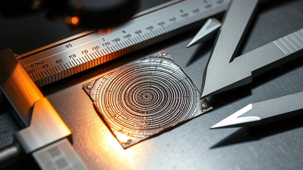
You need tools that produce a flat, representative cross-section without adding heat damage, deformation, deep scratches, edge rounding, or chemical stains.
Essential tools for weld macro testing help you prepare clean cross-sections and inspect weld details with more confidence.
- Sectioning equipment: Use a suitable band saw, metallographic saw, or wet abrasive cutoff machine for the final cut. Guards, workholding, coolant, and the correct cutting wheel help control damage.
- Grinding and polishing equipment: Use flat platens, suitable abrasive papers or disks, and polishing consumables when the required finish goes beyond grinding.
- Mounting equipment: Use an appropriate hot or cold mounting system when the sample is too small, irregular, sharp, or difficult to hold safely.
- Approved chemical etchant: Select the reagent and application method for the alloy and test requirement. Do not assume that an etchant for carbon steel is suitable for stainless steel, aluminum, nickel alloys, titanium, or dissimilar-metal welds.
- Cleaning and rinsing supplies: Use procedure-approved cleaners, rinse materials, neutralizing materials when specified, lint-free wipes, and clean drying equipment.
- Inspection equipment: Use controlled lighting, a magnifier or stereomicroscope when needed, and a camera that can include a calibrated scale.
- Measuring equipment: Depending on the test, use a steel rule, calipers, fillet-weld measuring software, reticle, or calibrated imaging system.
- Safety equipment: Use machine guards, eye and face protection, hearing protection, compatible chemical-resistant gloves, protective clothing, closed footwear, local exhaust, and spill equipment selected through the hazard assessment.
A clean, controlled preparation area is important. Proper ventilation and fume control also help reduce exposure during cutting and grinding, but chemical etching may require a functioning laboratory chemical hood rather than general room airflow.
Warning: Etchants may be corrosive, toxic, oxidizing, or flammable and may release harmful vapors. Read the current Safety Data Sheet, use the required chemical hood or local exhaust, wear compatible PPE, keep an approved spill plan available, and follow the written storage and disposal procedure. Do not mix an etchant from memory or an unapproved internet recipe.
What Common Defects Can Macro Etch Testing Reveal?
Macro etching can reveal discontinuities and geometry problems that intersect the prepared surface. The result depends on sample location, preparation quality, etchant response, lighting, and the size and orientation of the indication.
- Lack of fusion: The weld metal did not fuse completely with a joint face, root face, or previous weld pass.
- Incomplete penetration: The weld did not reach the required root depth or did not fuse through the joint as required.
- Porosity or cavities: Rounded or irregular voids may result from trapped gas, shrinkage, or another process condition.
- Cracking: Cracks may occur in the weld metal, root, crater, fusion boundary, or heat-affected zone and may run in different directions.
- Slag or nonmetallic inclusions: Entrapped material may appear within a pass or between passes.
- Undercut: A groove at the weld toe may reduce the local section thickness.
- Excessive or insufficient reinforcement: The weld face or root profile may fall outside the required dimensions.
- Asymmetry or poor bead placement: An uneven fusion pattern may point to joint-fit-up, angle, travel, heat-distribution, or access problems.
- Unwanted penetration or burn-through: Excessive root penetration or a hole may appear when heat input, root opening, or travel speed is unsuitable.
Macro etching may also show pass sequence, weld dilution, fusion-boundary shape, and the visible outline of the heat-affected zone. Better heat input management can reduce several fusion, profile, and distortion problems.
How to Interpret Macro Etch Test Results
Start by confirming the sample ID and orientation. Examine the unetched photograph first, then compare it with the etched surface. Review the complete cross-section before focusing on one dark line or spot.
Identify the base metal, weld metal, fusion boundaries, root, face, toes, and visible HAZ outline. Check whether the section represents the intended test location and whether preparation artifacts could be affecting the appearance.
Next, compare the required dimensions and permitted discontinuities with the welding procedure, drawing, code, or customer specification. Proper joint preparation improves both weld consistency and the usefulness of the resulting section.
Key Indicators of Quality
- Fusion and penetration: Check the root, joint sides, previous passes, and fusion boundaries for the required extent of fusion.
- Macrostructural features: Review the visible weld-pass pattern, HAZ outline, fusion-line shape, dilution pattern, and large-scale flow features.
- Weld profile: Examine the face, root, reinforcement, toe transition, symmetry, concavity, convexity, and any undercut.
- Visible discontinuities: Record the location, type, size, orientation, and number of cracks, pores, inclusions, cavities, or unfused areas exposed by the plane.
- Required dimensions: Measure penetration, leg length, actual throat, reinforcement, root opening, undercut depth, or other dimensions only when the governing method requires them.
A visually smooth section is not automatically acceptable. The acceptance criteria may restrict the size, position, or number of indications that are permitted.
Analyzing Defect Types
Use the macro result to identify likely process variables, but do not assign a root cause from appearance alone. Confirm the welding parameters, shielding conditions, consumables, fit-up, cleaning records, and welder observations.
| Observed Condition | What It May Mean | Items to Verify |
|---|---|---|
| Lack of fusion | The weld did not fuse fully with the base metal or a prior pass | Heat input, travel speed, torch or electrode angle, joint access, cleaning, and pass placement |
| Incomplete penetration | The root did not fuse to the required depth | Root opening, land thickness, bevel angle, current, travel speed, and electrode position |
| Porosity or cavities | Gas or shrinkage voids intersect the prepared plane | Moisture, contamination, shielding flow, leaks, drafts, consumable condition, and surface coatings |
| Inclusions | Nonmetallic material remained within or between weld passes | Slag removal, groove access, bead shape, cleaning, pass overlap, and technique |
| Undercut | A groove reduced the section near the weld toe | Travel speed, voltage or arc length, heat input, angle, weaving, and filler placement |
| Cracking | A crack intersects the sampled plane in the weld, fusion region, root, crater, or HAZ | Material condition, hydrogen control, restraint, preheat, interpass temperature, crater filling, and post-weld treatment |
How to Troubleshoot Preparation and Etching Problems
Not every line, dark area, or irregular edge is a weld defect. Preparation and etching can create artifacts that hide real features or imitate discontinuities.
| Problem | Likely Preparation Cause | Corrective Action |
|---|---|---|
| Deep parallel scratches | Damage from an earlier abrasive stage was not removed | Return to the appropriate abrasive and grind until the previous scratch direction is gone |
| Rounded root or weld toes | Uneven pressure, soft backing, poor support, or excessive polishing | Improve support, maintain planarity, reduce pressure, and use a suitable preparation surface |
| Smeared or dragged metal | Excessive pressure, unsuitable abrasive, inadequate lubrication, or a soft ductile material | Use the material-specific preparation method and reduce heat and deformation |
| Discolored or altered cut edge | Thermal cutting or overheating during sectioning and grinding | Remove the affected material and repeat the final cut or grinding with better cooling and lower damage |
| Weak or uneven contrast | Dirty surface, unsuitable etchant, uneven application, or insufficient reaction | Reprepare the surface if needed and repeat the approved etching procedure consistently |
| Dark staining or loss of detail | Over-etching, contaminated reagent, delayed rinsing, or poor drying | Remove the damaged surface, reprepare it, and repeat the controlled procedure with clean materials |
| Relief between weld and base metal | Different hardnesses or removal rates across the joint | Use a preparation sequence designed for dissimilar hardness and minimize excessive polishing time |
Note: When the result is unclear, do not force an interpretation. Regrind or repolish the surface, repeat the approved etch, and compare the new result with the original unetched photograph.
Products Worth Considering

Note: The etching cream is an essential component of the glass etching kit, however it is not suitable for use by children, do not swallow, and is not suitable for etching on borosilicate glass, acrylic or plastic surfaces

master your craft
How Weld Macro Testing Compares to Other Methods
Macro testing provides direct visual access to a prepared cross-section. Other inspection methods answer different questions, so the required combination depends on the weld, code, material, and service conditions.
| Method | Destructive? | Best Used For | Main Limitation |
|---|---|---|---|
| Visual inspection | No | Surface profile, dimensions, workmanship, and visible surface discontinuities | Cannot directly show the internal cross-section |
| Macro-etch examination | Yes | Weld geometry, fusion pattern, penetration, pass layout, HAZ outline, and visible indications in the sampled plane | Only the selected section is examined |
| Microscopic examination | Usually yes | Grain structure, phases, fine cracks, segregation, and detailed HAZ or weld-metal features | Needs finer preparation, higher magnification, and specialist interpretation |
| Bend testing | Yes | Ductility and the ability of a weld coupon to withstand prescribed deformation | Does not provide the same direct etched view of weld geometry |
| Radiographic or ultrasonic testing | No | Examining longer weld lengths for internal indications without cutting the part | Results depend on method capability, geometry, material, access, calibration, and operator qualification |
| Liquid penetrant or magnetic-particle testing | No | Surface-breaking or near-surface indications within the method’s material limits | Does not expose the complete weld cross-section |
Macro testing can highlight issues linked to welding parameters, but it cannot replace every required inspection. Critical work may require several complementary methods.
Essential Best Practices for Effective Macro Testing
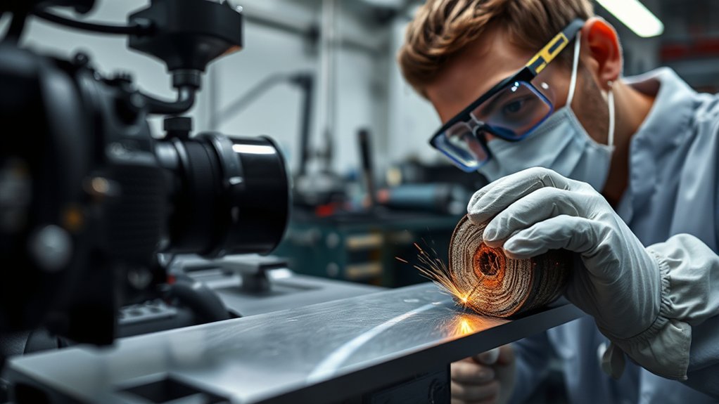
Reliable macro results depend on representative sampling, low-damage sectioning, a flat surface, a controlled etch, and consistent documentation. Record any departure from the approved method because it may change the appearance of the section.
If you test galvanized or coated material, address the coating before welding and sample preparation under the applicable workplace procedure. Zinc residue can affect welding and add fume risk during thermal work. This guide on zinc residue removal explains why controlled surface preparation matters.
Sample Preparation Techniques
- Protect traceability: Mark the sample ID, weld direction, face, root, and removal location before cutting.
- Control cutting damage: Use suitable workholding, blade or wheel selection, feed rate, and coolant. Remove material affected by any primary thermal cut.
- Keep the surface flat: Grind evenly so the root, weld toes, and joint edges are not rounded away.
- Remove each abrasive stage: Change grinding direction between steps when practical and continue until scratches from the previous stage are gone.
- Prevent contamination: Clean the sample, hands, holder, and preparation equipment between abrasive stages.
- Inspect before etching: Photograph voids, cracks, inclusions, scratches, and other visible conditions on the clean surface.
Do not rush the preparation. A rough cut, embedded abrasive, smeared metal, uneven relief, or deep scratch can hide a real discontinuity or create a false indication.
Proper Etching Procedures
Choose the etchant from the governing standard, qualified laboratory method, or approved shop procedure. Carbon and low-alloy steels, stainless steels, nickel alloys, aluminum alloys, copper alloys, and titanium alloys do not all respond to the same reagent.
Even within one joint, the weld metal and base metal may react at different rates. Dissimilar-metal welds may require a different method or more than one controlled examination to reveal all regions clearly.
| Step | Required Control |
|---|---|
| Confirm the material | Verify the base metal, filler metal, coating, and any dissimilar alloy before choosing the method |
| Review the procedure and SDS | Confirm the reagent, application method, exposure endpoint, ventilation, PPE, incompatibilities, first aid, storage, and disposal requirements |
| Prepare the work area | Use the specified chemical hood or local exhaust, compatible containers, labels, secondary containment, and spill materials |
| Apply consistently | Treat the clean surface evenly using the written immersion, swabbing, or electrolytic method |
| Watch the endpoint | Stop when the required regions have adequate contrast; do not continue merely to make the surface darker |
| Stop, rinse, and dry | Follow the exact procedure for rinsing or neutralizing, then dry promptly without staining or corrosion |
| Manage waste | Collect used reagent, rinsate, wipes, and contaminated materials in compatible labeled containers as required by the waste plan |
Safety Precautions Required
Macro testing combines machine, abrasive, noise, sharp-edge, dust, splash, chemical, and waste hazards. Control each hazard before starting.
- Complete a hazard assessment: Review the machines, material coatings, abrasive products, chemicals, and waste streams involved in the specific test.
- Use machine safeguards: Secure the sample, keep guards in place, use the correct wheel or blade, and follow lockout procedures before adjustments or maintenance.
- Protect the eyes and face: Wear the protection required for cutting and grinding. Use chemical splash goggles and a face shield when the chemical assessment requires both.
- Select compatible gloves: A glove that resists one etchant or solvent may not resist another. Use the SDS and workplace glove-selection guidance.
- Use effective ventilation: Perform chemical work in the specified hood or local-exhaust system. General ventilation alone may not control corrosive or toxic vapors.
- Keep chemicals labeled: Use approved, compatible containers with complete labels. Do not store unidentified mixtures.
- Do not rely casually on a respirator: Engineering controls are the first choice. Use respiratory protection only when required by the employer’s hazard assessment and respiratory-protection program.
- Plan for spills and exposure: Know the eyewash, safety shower, spill-kit, emergency-contact, and first-aid procedures before opening the chemical.
- Dispose of waste correctly: Keep incompatible wastes separate and do not use sink disposal unless the approved environmental and safety procedure specifically allows it.
How to Apply Macro Test Findings
Start by listing each relevant observation and its location. Separate confirmed weld discontinuities from preparation artifacts and items that remain uncertain. Record whether each observation was visible before etching, after etching, or both.
Connect the findings to process evidence rather than guessing from appearance alone. Review the welding current or voltage, travel speed, wire feed, shielding flow, consumable condition, joint dimensions, cleaning, preheat, interpass temperature, sequence, and welder notes.
Use the findings to improve welding parameters and welder training. If several representative samples show the same condition, review both the welding procedure and the way it is applied. Addressing recurring issues such as lack of fusion can improve process consistency.
When a sample does not meet the acceptance criteria, follow the project’s nonconformance procedure. Do not automatically approve a production weld because a nearby practice coupon looked satisfactory, and do not change an approved welding procedure without the required review or requalification.
What to Record After a Weld Macro Test
A weld macro test is more useful when another qualified person can trace, understand, and repeat the examination. Tie every record to the exact sample, weld, procedure, welder or operator when applicable, and test date.
Record at least the following information when it applies:
- Project, assembly, weld, coupon, and sample identification
- Drawing and welding-procedure revisions
- Welder or operator identification when required
- Welding process, position, joint type, and pass sequence
- Base metal, thickness, filler metal, and shielding information
- Sample location, orientation, face, root, and welding direction
- Sectioning, mounting, grinding, and polishing method
- Etchant identification and approved procedure reference
- Inspection condition, lighting, magnification, and measurement equipment
- Unetched and etched photographs with scale and orientation
- Required weld dimensions and recorded measurements
- Observed discontinuities, locations, sizes, and classifications
- Applicable acceptance criteria and pass, fail, or further-review decision
- Inspector or examiner identification and review date
- Any preparation difficulty, repeated etch, deviation, or uncertainty
Keep the original image files when possible. A report image that has been resized, sharpened, or compressed may not preserve all of the details visible during the examination.
Frequently Asked Questions
What Is Macro Testing in Welding?
Macro testing examines a prepared cross-section of a weld by eye or at low magnification. Grinding or polishing and controlled etching reveal large-scale features such as weld geometry, penetration, fusion boundaries, the heat-affected zone, pass layout, and visible discontinuities that intersect the section.
How Long Does a Weld Macro Test Usually Take?
A simple unmounted shop coupon may be prepared and reviewed in less than an hour when equipment and an approved method are ready. Large, mounted, highly polished, difficult-to-etch, reworked, measured, or formally documented samples can take several hours. There is no universal test time.
What Is the Hardest Weld Test?
There is no single hardest weld test. Difficulty depends on the welding process, material, thickness, joint, position, access, and acceptance standard. Pipe qualification tests, overhead welding, bend tests, and tests on reactive or crack-sensitive alloys may be challenging for different reasons.
What Is the Procedure of a Macro Etch Test?
Confirm the governing method, select and mark a representative section, cut it with controlled damage, grind it flat, polish when required, clean and inspect it before etching, apply the approved material-specific etchant, stop and clean the surface as directed, inspect and measure the section, and document the result against the correct acceptance criteria.
Can a Weld Macro Test Replace Non-Destructive Testing?
No. A macro test requires removing and preparing a sample, and it examines only the selected plane. Non-destructive methods can inspect a component without cutting it and may cover a much longer weld length. Use the methods required by the governing code or specification.
Is a Weld Macro Test Destructive?
Yes. The normal method removes a section through the weld and permanently alters its surface through grinding, polishing when required, and etching. Tests are therefore commonly performed on qualification coupons, production samples, mockups, or parts selected for destructive examination.
What Is the Difference Between Macro and Micro Examination?
Macro examination studies large-scale weld features by eye or at low magnification and may require only a ground or moderately finished surface. Micro examination uses a more finely polished surface and higher magnification to study grain structure, phases, fine cracks, segregation, and detailed changes in the weld and heat-affected zone.
What Magnification Is Used for a Weld Macro Test?
Macro sections are examined with the unaided eye or low-magnification optics. There is no universal 20× limit for every application. Use the magnification and calibrated scale required by the applicable standard, procedure, feature size, and measurement method.
Can a Macro Test Qualify a Welding Procedure or Welder?
A macro test may be one required part of a procedure, performance, or production qualification when the governing code or specification permits it. The section must be taken from the prescribed location, prepared by the required method, and evaluated against that document’s acceptance criteria. A general-purpose macro photograph does not create a qualification by itself.
Safety Disclaimer: This article is for informational purposes only and does not replace professional welding, metallography, laboratory, chemical-safety, or inspection training. Follow the applicable welding code, workplace chemical-hygiene plan, written test procedure, equipment instructions, and current Safety Data Sheet before cutting, grinding, polishing, etching, storing, or disposing of any material.
Conclusion
A weld macro test gives a direct view of the geometry and visible macrostructure within a prepared weld cross-section. It can expose penetration, fusion patterns, profile problems, cracking, porosity, inclusions, and other indications that intersect the sampled plane.
Trustworthy results begin before etching: select a representative location, protect sample orientation, control cutting heat and deformation, keep the surface flat, inspect it unetched, and use a material-specific approved reagent. Record the findings with a scale and compare them only with the acceptance criteria that govern the job. Used with the required visual, mechanical, and non-destructive tests, macro examination can guide better welding habits and more consistent quality control.
Sources
- ASTM E340-23: Standard Practice for Macroetching Metals and Alloys — macroetching scope, uses, weld penetration, discontinuities, and safety responsibility
- ISO 17639:2022: Macroscopic and Microscopic Examination of Welds — current ISO guidance for weld-specimen preparation and examination
- ISO/TR 16060: Etchants for Macroscopic and Microscopic Examination of Welds — material groups and selection of suitable etchants
- Struers: Metallographic Weld Inspection — low-damage sectioning, mounting, grinding, polishing, etching, magnification, and weld-examination limitations
- Buehler: Welding Metallography for Ferrous Metals — specimen removal, pre-etch inspection, preparation, and examination of weld discontinuities
- OSHA: Chemical Hygiene in Laboratories — chemical hoods, eye and face protection, compatible gloves, labeling, and waste-management practices




