
Weld dilution is the share of melted base metal that becomes part of the final weld metal. It matters most when the base metal and filler metal have different chemistry, such as in stainless overlays, hardfacing, repair welding, and dissimilar-metal joints. The goal is not always the lowest possible dilution. The goal is the dilution range that gives complete fusion and the required weld-metal properties.
Quick Answer
Weld dilution is the percentage of the finished weld metal that came from melted base metal. It changes weld chemistry and may affect cracking, hardness, toughness, wear, and corrosion resistance. Control it through a qualified procedure, suitable filler metal, joint geometry, bead placement, current, voltage, travel speed, and deposition rate.
Key Takeaways
- Dilution measures base-metal contribution to the weld metal; it is not the same as penetration or fusion quality.
- There is no universal “good” percentage. The acceptable range depends on the materials, filler, process, layer, service, and governing procedure.
- A process name alone does not predict dilution. Current, polarity, transfer mode, travel speed, wire feed, bead overlap, and joint shape can change it.
- Cross-section area is a common estimate, while chemical analysis can give a better answer for dissimilar-metal deposits and overlays.
- High dilution is most concerning when it moves weld chemistry outside the range needed for corrosion, wear, toughness, or crack resistance.
What’s in This Article
- What Is Weld Dilution and Why Is It Important?
- Weld Dilution vs. Penetration and Fusion
- How Does Dilution Change Weld Quality?
- Factors Influencing Weld Dilution
- How to Calculate Weld Dilution: Methods and Examples
- What Are the Mechanical Effects of Dilution?
- Techniques for Effective Dilution Control
- Common Welding Problems Related to Excessive Dilution
- How to Prevent Dilution-Related Problems
- Inspection and Procedure Qualification
- Best Practices for Achieving the Required Weld Dilution
- Welding Safety When Adjusting Dilution
- Frequently Asked Questions
What Is Weld Dilution and Why Is It Important?
Weld dilution is the amount of melted base metal, or previously deposited weld metal, that mixes with the new weld deposit. It is normally expressed as a percentage of the final weld metal.
For example, 20% dilution means about 20% of the weld metal came from the base material and about 80% came from filler metal. In an autogenous fusion weld made without filler, the weld metal comes from the base material, so the base-metal contribution is effectively 100%.
Dilution matters because the weld does not always keep the exact chemistry printed on the filler-metal package. The final composition is a blend of the filler, the base metal, and sometimes an earlier weld layer. That blend can change hardness, ferrite balance, strength, toughness, wear resistance, and corrosion behavior.
Dilution control is especially important in:
- Corrosion-resistant overlays, where iron from a carbon-steel substrate can reduce alloy content at the surface.
- Hardfacing, where excess base-metal mixing can lower hardness or change the intended wear microstructure.
- Dissimilar-metal welds, where the mixed composition may form hard, brittle, or crack-sensitive zones.
- Repair and buildup welding, where the original part chemistry may differ from the repair consumable.
- Stainless and nickel-alloy joints, where chromium, nickel, molybdenum, carbon, and ferrite balance may be critical.
A TWI weld-overlay study found that dilution within one arc-welding process could vary over a wide range as parameters changed. The study also showed that the same calculated heat input could produce very different dilution when current and travel speed were combined differently. See the TWI research on weld-overlay dilution.
There is no universal ideal dilution percentage. The correct target is the range that produces complete fusion and the required chemistry and properties for the specific weld.
Weld Dilution vs. Penetration and Fusion
Dilution, penetration, and fusion are related, but they do not mean the same thing.
- Dilution describes how much base metal became part of the weld metal.
- Penetration describes how far the fusion extends into the joint or base metal.
- Fusion means the weld metal properly bonded with the base metal or a previous weld bead.
A weld can have low dilution and still have acceptable fusion when a high deposition rate places a large amount of filler over a shallow but sound fusion zone. A weld can also have high dilution and still fail because its chemistry, bead shape, or solidification behavior is unsuitable.
Lack of fusion and lack of penetration are therefore not automatic results of high dilution. They are separate weld discontinuities that must be checked through procedure control and inspection.
Note: Do not use dilution percentage as a substitute for fusion inspection. A low-dilution overlay may still be sound, while a visually smooth bead may still hide incomplete fusion.
How Does Dilution Change Weld Quality?
Dilution changes weld quality by changing the composition of the liquid weld pool and the microstructure that forms as it cools. The effect can be helpful, neutral, or harmful depending on the materials and the required service properties.
Effects on Chemical Composition
When filler and base metals have different chemistry, the final weld-metal composition falls somewhere between them. A simple first estimate uses a mass-balance equation:
Estimated weld composition = (dilution fraction × base-metal composition) + [(1 − dilution fraction) × filler-metal composition]
For example, assume a filler contains 20% chromium, the base steel contains 0.2% chromium, and dilution is 20%:
Estimated chromium = (0.20 × 0.2) + (0.80 × 20) = 16.04%
This simplified estimate assumes complete, even mixing and no element loss. Real welds may have local composition gradients, incomplete mixing near the fusion boundary, flux reactions, or element loss. Use chemical testing when the specification requires a verified result.
Impact on Mechanical Properties
Dilution can change hardness, tensile behavior, ductility, impact toughness, and wear performance. The direction of the change depends on what the base metal adds to the weld pool.
For example, carbon pickup from a high-carbon or cast-iron base can create hard, crack-sensitive weld metal. In a hardfacing deposit, too much low-alloy base metal can reduce the alloy level and lower wear resistance. In other combinations, controlled base-metal mixing may help the deposit reach the intended composition.
That is why a percentage cannot be judged by itself. You must compare the resulting chemistry and test results with the approved welding procedure and service requirements.
Influence on Weld Integrity
Dilution affects weld integrity when it changes solidification behavior or creates an unfavorable microstructure. Higher base-metal contribution can increase the amount of carbon, sulfur, phosphorus, iron, or other elements in the weld pool, depending on the materials being joined.
Those changes may raise solidification-cracking risk, create hard zones, upset ferrite balance, or reduce corrosion resistance. TWI notes that plate and filler composition both influence solidification cracking, and that plate chemistry becomes more important in high-dilution conditions. See its guidance on solidification cracking.
Factors Influencing Weld Dilution
Many variables affect how much base metal melts and how much filler is deposited per unit length. They work together, so changing one setting can produce a different result when another setting also changes.
- Welding current and polarity: Higher current often increases melting and penetration, but its net effect depends on deposition rate, polarity, and process.
- Voltage and arc length: These change arc shape, bead width, and heat distribution.
- Travel speed: Faster or slower travel does not have one universal effect. The result depends on current, wire feed, bead size, and deposited filler per unit length.
- Wire-feed or filler-addition rate: More filler for the same melted base-metal area usually lowers the dilution percentage.
- Transfer mode: Short-circuit, globular, spray, pulsed, and controlled transfer modes produce different penetration and deposition patterns.
- Joint design and fit-up: Groove angle, root opening, land, backing, and plate thickness change the amount of base metal that enters the pool.
- Electrode or torch angle: Arc direction changes penetration, toe fusion, and bead placement.
- Bead overlap and layer number: The first layer normally receives the greatest direct contribution from the substrate. Later layers mix more with earlier weld metal.
- Shielding gas and flux: Gas composition and flux behavior can change arc energy, transfer, penetration, and chemistry.
- Welding position and technique: Gravity, weave width, oscillation, and bead placement affect pool shape and mixing.
Different welding processes have different tendencies, but broad fixed percentages are unreliable without the full procedure. A GTAW overlay, for example, can have low or high dilution depending on current, filler rate, speed, and bead overlap. The same warning applies to GMAW, SMAW, FCAW, and SAW.
Use amperage guidance only as a starting point. Final settings must come from the consumable data, joint design, test welds, and the applicable WPS.
Pro Tip: Record current, voltage, polarity, wire-feed speed, travel speed, filler size, gas, torch angle, bead overlap, and layer number. “Heat input” alone may not explain why dilution changed.
How to Calculate Weld Dilution: Methods and Examples
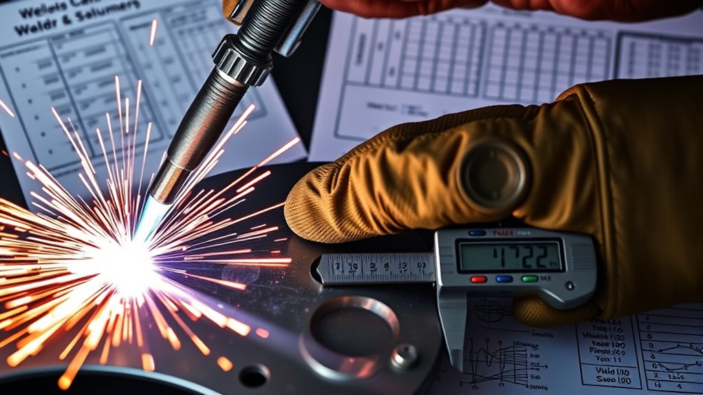
You can estimate weld dilution from a polished cross-section, direct mass measurements, or chemical analysis. The best method depends on the weld type and how different the base and filler metals are.
Key Calculation Formulas
1. Cross-section area method
For a bead-on-plate deposit:
Dilution (%) = [melted base-metal area ÷ (melted base-metal area + deposited weld area)] × 100
The melted base-metal area is the portion below the original surface. The deposited weld area is the reinforcement above it. For groove welds, include all melted base-metal regions that contribute to the fusion zone.
This geometric method is widely used, but it is an estimate. It assumes the section represents the stable bead and may not fully describe chemical mixing in dissimilar materials. An ASME study describes dilution as the melted base-material area divided by the total fusion-zone area, while research has also examined chemical-composition methods where area alone is not enough. See the ASME dilution study and the Metals paper on dilution calculation.
2. Mass method
Dilution (%) = [mass of melted base metal ÷ total mass of weld metal] × 100
This method is conceptually direct but often difficult to use in production because the melted base-metal mass is not easy to measure separately. If you convert areas or volumes to mass, account for density differences between dissimilar alloys.
3. Chemical back-calculation
When one element has clearly different concentrations in the base and filler metals, dilution can be estimated from:
Dilution fraction = (measured weld concentration − filler concentration) ÷ (base concentration − filler concentration)
Multiply the result by 100 for a percentage. This approach needs reliable composition data and a suitable tracer element. It may not work well when an element is lost, added by flux, or unevenly mixed.
Factors Affecting the Calculated Dilution Rate
Your answer can change depending on where and how you measure:
- Section location: Start and stop areas may not represent the stable part of the bead.
- Original surface line: An incorrect reference line changes the measured areas.
- Etching and image quality: A faint fusion boundary makes area tracing less accurate.
- Density difference: Equal areas do not always mean equal mass when alloys have different densities.
- Local segregation: One chemistry reading may not represent the whole bead or layer.
- Previous layers: A later bead may mix with both the base metal and earlier weld metal.
Example Calculation Scenarios
Area example: A polished cross-section shows 12 mm² of melted base metal and 48 mm² of deposited weld metal.
Dilution = 12 ÷ (12 + 48) × 100 = 20%
Filler-to-base ratio example: If a stated ratio truly means 10 parts filler metal to 1 part base metal, the base-metal share is:
1 ÷ (10 + 1) × 100 = 9.1% dilution
Always state which material comes first in a ratio. “10-to-1 dilution” by itself is ambiguous and is not a clear substitute for a percentage.
Processes such as flux-core welding can produce different dilution as current, voltage, electrode extension, travel speed, and deposition rate change. Do not copy a percentage from another process or joint without testing.
What Are the Mechanical Effects of Dilution?
Dilution affects mechanical performance only through the chemistry, microstructure, geometry, and defects that result. Common concerns include:
- Hardness changes: Carbon or alloy pickup can create hard, crack-sensitive weld metal or heat-affected zones.
- Toughness changes: An unfavorable microstructure can reduce impact resistance.
- Strength mismatch: The weld may become weaker or stronger than intended, which can move strain into a vulnerable zone.
- Crack susceptibility: Changed chemistry and bead shape can raise solidification or cold-cracking risk.
- Wear resistance: Base-metal mixing can dilute hardfacing elements and reduce abrasion resistance.
- Corrosion resistance: Iron pickup or loss of chromium, nickel, molybdenum, or nitrogen balance can reduce overlay performance in a specific environment.
- Layer effectiveness: The first overlay layer may not meet final surface chemistry, so a second or third controlled layer may be required.
These effects are material-specific. High dilution is not automatically harmful in every groove weld, and low dilution is not automatically proof of quality. The WPS, filler classification, design code, and service test requirements define what is acceptable.
Understanding how flux-core welding is used can help you choose a suitable process, but the process still needs qualification for demanding overlays or dissimilar joints.
Techniques for Effective Dilution Control
Control dilution by managing both sides of the percentage: how much base metal melts and how much filler metal is deposited.
| Technique | How It Can Affect Dilution | Control Point |
|---|---|---|
| Adjust current and polarity | Changes base-metal melting, penetration, and electrode melting | Stay within the qualified range; do not judge by amperage alone |
| Balance travel and deposition rate | Changes filler deposited per unit length and the weld-pool shape | Track travel speed with wire feed or manual filler addition |
| Change transfer mode or process variant | Changes arc force, penetration profile, and deposition efficiency | Requalify when required by the governing code or WPS |
| Improve joint design and fit-up | Changes the amount of base metal exposed to the arc | Use the specified groove, root opening, land, and backing |
| Control bead overlap and sequence | Later beads remelt more weld metal and less virgin substrate | Keep overlap, bead placement, and layer count consistent |
| Select an over-alloyed or matching filler | Compensates for the predicted base-metal contribution | Use filler approved for the material pair and service need |
| Use multiple overlay layers | Reduces direct substrate influence at the final surface | Verify final-layer chemistry and minimum finished thickness |
Maintaining suitable amperage output is part of control, but changing machine size or current without considering deposition rate can move dilution in the wrong direction.
Products Worth Considering
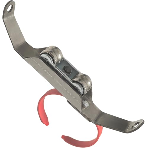
【Ergonomic TIG Feeder】This TIG rod feeder consists of a wire guide bracket, wire guide holes, wire guide wheels, and a fixing ring. The wire guide bracket can be bent back and forth to fix the welding wire. There are two wire guide wheels, ensuring more stable wire feeding. The fixing ring features an open design that allows size adjustment, enabling it to accommodate gloves of various sizes. It also supports 360° rotation, allowing you to customize your most comfortable welding posture.
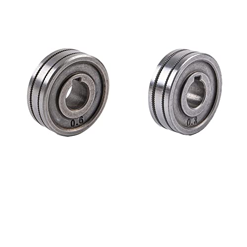
These rollers are used for feeding MIG wire on welding machines, fits directly onto the motor shaft.

Precision in TIG Welding: designed specifically for TIG welding, this TIG feeder ensures accurate and precise wire feeding; Achieve nice welding results every time by maintaining consistent wire delivery, crucial for both professional and hobbyist welders who demand quality and reliability from their tools
Common Welding Problems Related to Excessive Dilution
Excessive dilution is mainly a chemistry and metallurgy problem. It may contribute to:
- Loss of corrosion resistance: The final layer may contain too much iron or too little of the alloying elements needed for the service environment.
- Reduced hardfacing performance: Base-metal mixing may lower carbide-forming or hardening elements.
- Solidification cracking: Base-metal impurities or an unfavorable mixed composition can increase crack sensitivity.
- Hard or brittle microstructures: Carbon and alloy mixing may form martensite, brittle phases, or a severe hardness gradient.
- Ferrite imbalance: Stainless weld metal may fall outside the intended ferrite or phase balance.
- Extra layers and rework: The first deposit may fail chemistry, hardness, or corrosion requirements and need additional buildup.
Lack of fusion and lack of penetration should be evaluated separately. A method chosen to lower dilution can create a high, convex bead or poor toe access if bead placement is wrong, but low dilution itself is not proof of incomplete fusion. TWI reported that a controlled short-circuit process produced low dilution in an overlay study while its bead shape increased the risk of toe lack of fusion unless torch positioning was carefully controlled.
A welder’s duty cycle protects the machine from overheating. It does not directly set weld dilution, so do not treat duty-cycle percentage as a dilution-control value.
Warning: Do not raise current or flatten the bead only for appearance. A smoother-looking bead can still have excessive base-metal mixing, an unfavorable depth-to-width ratio, or unacceptable chemistry.
How to Prevent Dilution-Related Problems
Use a controlled sequence rather than changing one setting at random:
- Identify the required property. Decide whether the critical limit is chemistry, hardness, ferrite, corrosion resistance, wear, toughness, or another project requirement.
- Confirm the material pair. Verify base-metal grade, filler classification, coating, previous weld metal, and service condition.
- Set the target through the procedure. Use the applicable WPS, code, engineering specification, and consumable guidance.
- Make a stable test bead or coupon. Record every essential setting and technique variable.
- Measure the result. Use macroetching, area measurement, chemistry, hardness, ferrite testing, or corrosion testing as required.
- Change one controlled variable at a time. Adjust current, polarity, travel, filler rate, bead overlap, or joint design within permitted limits.
- Recheck fusion and bead shape. Do not reduce dilution at the expense of toe fusion, root fusion, or adequate bond.
- Qualify or requalify when required. Production welding must stay within the procedure and governing code.
Choose the right filler material for the exact base-metal combination. A filler that is correct for one stainless grade may be unsuitable for a dissimilar joint or a high-dilution first layer.
For galvanized or coated steel, remove coatings only by an approved method and control the fumes. Review safe practices for welding galvanized steel, and follow the safety requirements in the next section.
Inspection and Procedure Qualification
Visual inspection alone cannot confirm dilution. Use the method that matches the risk:
- Macroetch cross-section: Shows fusion profile, penetration, bead shape, and geometric dilution area.
- Chemical analysis: Checks whether the deposit reached the required alloy content. Sampling location and depth matter.
- Hardness mapping: Finds hard zones and steep property changes near the fusion boundary.
- Ferrite or phase measurement: Helps evaluate certain stainless and duplex deposits when required.
- Corrosion or wear testing: Confirms performance in a specified test environment.
- Nondestructive testing: Finds cracks, lack of fusion, porosity, and other discontinuities, but normally does not measure dilution percentage directly.
A Procedure Qualification Record (PQR) records the actual variables and test results from a qualification coupon. A Welding Procedure Specification (WPS) gives the permitted production variables. They are not interchangeable.
The American Welding Society explains that Standard Welding Procedure Specifications are supported by PQRs and must meet the applicable qualification rules. Review the AWS guidance on SWPSs and PQR support.
Best Practices for Achieving the Required Weld Dilution
- Define the target from performance needs, not a generic internet percentage.
- Use verified base-metal and filler-metal identities.
- Follow the qualified joint design, polarity, transfer mode, and parameter ranges.
- Track deposition rate with current and travel speed.
- Keep bead placement, overlap, and layer sequence repeatable.
- Measure both dilution and fusion quality.
- Verify final-layer chemistry after machining or grinding to finished thickness.
- Document changes and requalify when the code or contract requires it.
When sizing fillet welds, match the weld size to the drawing, joint design, and thinner member rather than adding unnecessary weld metal and heat. See this guide to fillet weld size for plate thickness.
Consistent procedure control also helps you weld faster without losing weld quality. Productivity changes should be tested because higher current and faster travel can change dilution even when calculated heat input looks similar.
Welding Safety When Adjusting Dilution
Changing parameters can increase fumes, ultraviolet radiation, spatter, hot-metal exposure, and fire risk. Use the correct helmet shade, protective clothing, gloves, hearing protection, and ventilation for the process and materials.
OSHA requires controls for hazardous welding fumes and gases and addresses ventilation, coatings, confined spaces, and hazard communication in 29 CFR 1910.252. Do not weld coated, plated, painted, or unknown metal until the hazards have been identified and the required controls are in place.
Warning: Welding fumes can be hazardous. Use source capture or suitable ventilation, follow the Safety Data Sheets for fillers and coatings, and use respiratory protection only as part of a compliant respiratory-protection program.
Frequently Asked Questions
What is dilution in welding?
Dilution is the percentage of the final weld metal that came from melted base metal or previously deposited weld metal. It changes the final weld chemistry and may affect hardness, toughness, cracking, wear, and corrosion performance.
What does a 10-to-1 dilution ratio mean?
The phrase is ambiguous unless the order is stated. If it means 10 parts filler metal to 1 part base metal, the base-metal share is 1 divided by 11, or about 9.1% dilution. Use a percentage and identify the calculation method whenever possible.
What is the golden rule in welding?
There is no single official golden rule for every welding job. A sound general rule is to follow the approved WPS, verify the materials, control the essential variables, protect yourself from the hazards, and inspect the finished weld against the applicable acceptance criteria.
What does 5% dilution mean?
It means about 5% of the final weld metal came from the base material and about 95% came from filler or previously deposited weld metal. Whether 5% is acceptable depends on the application and the qualified procedure.
How can you reduce weld dilution?
You can reduce dilution by limiting unnecessary base-metal melting, increasing suitable filler deposition, changing transfer mode or polarity, improving bead placement, controlling overlap, and adding qualified overlay layers. Any change must stay within the WPS and must not cause incomplete fusion.
Is high weld dilution always bad?
No. Significant base-metal contribution is normal in many groove welds. High dilution becomes a problem when it moves chemistry, microstructure, hardness, corrosion resistance, or another required property outside the acceptable range.
Can heat input alone predict dilution?
No. Heat input is useful, but current, travel speed, deposition rate, polarity, transfer mode, joint geometry, and bead overlap also matter. Two procedures with similar calculated heat input can produce different penetration and dilution.
Safety Disclaimer: This article is for general education and does not replace welding training, an approved WPS, project specifications, the governing code, Safety Data Sheets, or inspection by qualified personnel. Follow site rules and applicable safety regulations.
Conclusion
Weld dilution tells you how much base metal became part of the weld metal, but the number has meaning only when you connect it to chemistry, fusion, microstructure, and service requirements.
Do not rely on a universal process percentage or on heat input alone. Verify the materials, use a suitable filler, control current and deposition together, keep bead placement consistent, and measure the result with the method required by the job.
For critical overlays, pressure equipment, hardfacing, repairs, and dissimilar-metal joints, use a qualified procedure and confirm the final layer’s chemistry and properties before the component enters service.
Sources
- TWI: CRA Weld Overlay — Influence of Welding Process and Parameters on Dilution and Corrosion Resistance — supports the definition, parameter sensitivity, layer effects, and limits of heat input alone.
- ASME Journal of Pressure Vessel Technology: Prediction of Dilution and Its Impact on Metallurgical and Mechanical Behavior — supports the cross-sectional area definition and engineering importance of dilution.
- Metals: A New Method for Weld Dilution Calculation Through Chemical Composition Analysis — supports chemical-analysis methods and limitations of geometry-only estimates.
- TWI: Solidification Cracking — supports the effects of plate and filler chemistry, bead shape, impurities, and welding speed on cracking.
- American Welding Society: Standard Welding Procedure Specifications — supports the role of procedure qualification records and qualified procedure limits.
- OSHA 29 CFR 1910.252 — supports ventilation, hazard communication, confined-space, and welding-fume safety requirements.




