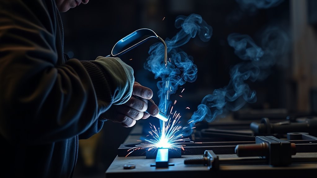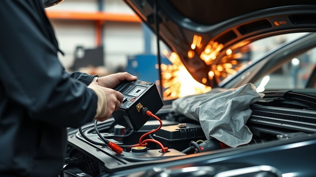
Welding on a car can damage ECUs, sensors, wiring, batteries, and control modules when the repair is not prepared correctly. You need to control the welding-current path, isolate the electrical systems specified by the vehicle maker, protect nearby components from heat and spatter, and check the vehicle before and after the repair.
Last reviewed: July 19, 2026
Quick Answer
Yes. Arc welding on a vehicle can damage ECUs, sensors, wiring, and other modules if current or heat reaches them. Follow the exact OEM procedure, isolate the required low- and high-voltage systems, place the work clamp beside the weld on clean metal, protect nearby components, control fire hazards, and scan the vehicle afterward.
Key Takeaways
- Read the vehicle-specific repair procedure before disconnecting a battery, module, SRS component, or high-voltage system.
- Use a welding work clamp, often called a ground clamp, on clean metal as close to the weld as possible and preferably on the same panel.
- Do not let weld current pass through bearings, hinges, axles, springs, wiring, modules, or braided ground straps.
- Remove or protect nearby wiring, sensors, trim, foam, seam sealer, fuel lines, brake lines, and other heat-sensitive parts.
- Record a pre-repair scan when required, then complete the OEM-required post-repair scan, initialization, aiming, or calibration.
- A battery surge protector does not replace electrical isolation, correct clamp placement, or the OEM repair procedure.
Warning: This is general safety guidance, not a substitute for the vehicle maker’s service information. Structural welding, SRS work, fuel-system repairs, and hybrid or EV repairs should be completed only by technicians with the required training, tools, PPE, and authorization.
At a Glance
| Time Required | Varies by vehicle and repair. OEM research, electrical isolation, preparation, cooling, fire monitoring, and diagnostics may take longer than the weld itself. |
| Difficulty | Advanced. Structural, SRS, hybrid, and EV work may require an OEM-qualified or specially trained technician. |
| Tools Needed | Approved welder, work clamp, battery tools, OEM repair information, cleaning tools, welding blankets, PPE, suitable fire extinguisher, lighting, and an OEM-capable scan tool when required |
| Main Risk | Stray current, voltage differences, electromagnetic interference, heat damage, fire, toxic fumes, structural damage, and hidden module faults |
| Cost | Depends on the repair, service-information access, component removal, diagnostic scanning, calibration, and corrosion-protection work |
How Welding on a Car Can Damage Electronics
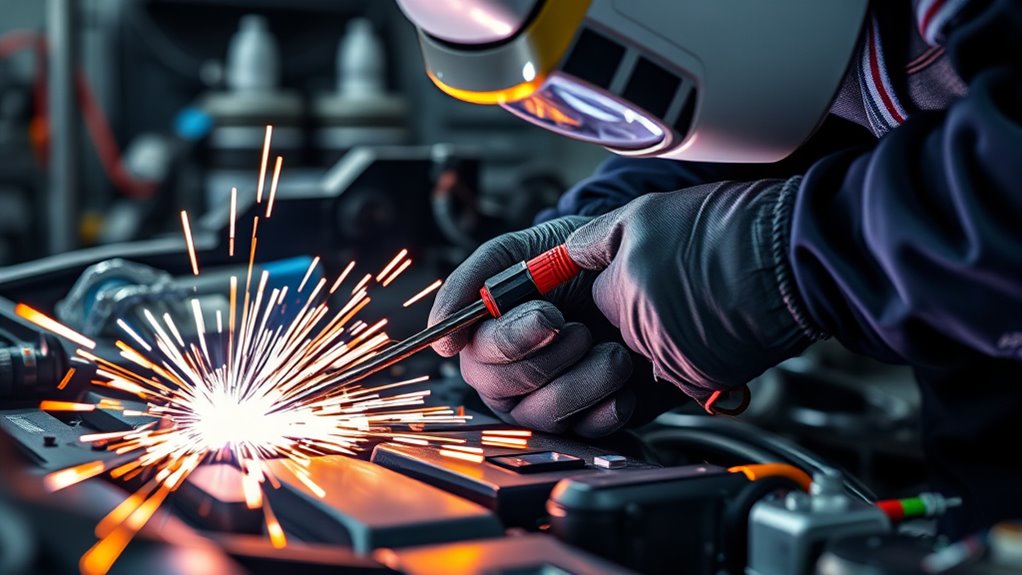
Arc welding creates a high-current circuit between the electrode, the vehicle metal, and the welder’s work clamp. When the return path is short and direct, most welding current stays in the intended repair area. When the path is long, dirty, or indirect, current may travel through body joints, brackets, fasteners, braided straps, hinges, bearings, cables, or other conductive parts.
Modern vehicles contain many electronic control units connected through shared power, ground, and communication networks. Unwanted voltage differences, electrical noise, heat, or direct current flow can cause warning lights, communication faults, sensor errors, damaged wiring, or failed modules. A problem may appear immediately, or it may remain hidden until the vehicle completes a drive cycle or operates the affected system.
Disconnecting the battery reduces risk, but it does not replace correct work-clamp placement. Some vehicles also have backup power supplies, SRS energy storage, telematics units, multiple low-voltage batteries, or a high-voltage traction battery. Follow the exact vehicle procedure for every system that must be shut down, isolated, disconnected, or removed.
The safest welding-current path is short, clean, predictable, and kept away from electronic modules, wiring, bearings, and moving components.
I-CAR’s general GMA welding guidance recommends placing the work clamp close to the weld on the same panel, isolating the battery cables, routing welding cables away from computers and wiring, and removing sensitive electronic parts when the repair is too close to them.
Warning: Never assume that disconnecting one battery terminal makes the vehicle safe to weld. Clamp placement, module isolation, high-voltage shutdown, wiring protection, heat control, fire preparation, and OEM repair limits still apply.
Understand the Work Clamp Before You Start
The clamp connected to the welding machine is technically the work clamp or return clamp. Welders often call it the ground clamp or earth clamp, but its main job is to complete the welding circuit. It is not a substitute for protective electrical grounding, and it should not be attached to a vehicle lift, battery terminal, unrelated chassis point, or building ground.
Place the work clamp on the metal involved in the repair. The intended path should run from the arc through a short section of solid metal and directly back to the clamp. Do not create a path that crosses:
- Wheel bearings, steering bearings, or driveline bearings
- Door, hood, hatch, or tailgate hinges
- Axles, springs, shocks, or suspension joints
- Engine, transmission, or electric-drive components
- Brake, throttle, parking-brake, or shift cables
- Wiring harnesses, braided ground straps, sensors, or control modules
If two separate pieces are being joined, confirm that the approved clamp arrangement gives both pieces a reliable return path without forcing current through an unintended joint or component.
Run a Pre-Weld Diagnostic Scan When Required
A pre-repair scan records the vehicle’s condition before you disconnect batteries, unplug modules, remove panels, or begin welding. This baseline can show whether a diagnostic trouble code existed before the repair and can identify systems that need special shutdown, initialization, aiming, or calibration procedures.
For collision-related work, follow the vehicle maker’s scanning position statement and repair manual. Manufacturers may require a full-system pre-scan, a post-repair scan, or both. Some faults do not turn on a warning light, so checking only the dashboard is not enough.
- Stabilize the vehicle’s low-voltage supply if the OEM diagnostic procedure requires approved support equipment.
- Use an OEM-approved or properly capable scan tool.
- Record all diagnostic trouble codes and module communication results.
- Save the report before clearing or disconnecting anything.
- Research each relevant code and any required calibration or initialization.
Note: Do not clear pre-existing codes simply to obtain a clean scan. Record them first so you can separate prior conditions from repair-related problems.
Products Worth Considering
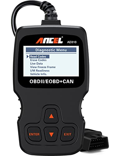
CEL Doctor: The ANCEL AD310 is one of the best-selling OBD II scanners on the market and is recommended by Scotty Kilmer, a YouTuber and auto mechanic. It can easily determine the cause of the check engine light coming on. After repairing the vehicle's problems, it can quickly read and clear diagnostic trouble codes of emission system, read live data & hard memory data, view freeze frame, I/M monitor readiness and collect vehicle information

Understand Your Check Engine Light – The ANCEL AD410 OBD2 scanner helps everyday drivers quickly read and clear engine-related fault codes, view code definitions, and understand why the check engine light is on before visiting a repair shop. With 42,000+ built-in DTC lookups, this car code reader helps reduce guesswork and makes basic vehicle diagnostics easier for beginners and DIY users

【UNIVERSAL COMPATIBILITY】This 38 pin to 16 pin OBD adapter allows connection between vehicles with 38 pin diagnostic sockets and code readers with 16 pin connectors.
Disconnect the Battery Before Welding
Turn the vehicle off, remove the key or move transmitters away as directed, and allow the vehicle’s modules to enter the required shutdown state. Then follow the exact battery-disconnect procedure in the service information. Do not rely on a universal waiting period because shutdown and residual-energy times differ between vehicles and systems.
General welding guidance commonly calls for disconnecting and isolating both conventional battery cables, with the negative cable removed first. However, the OEM may specify one cable, both cables, multiple batteries, a backup battery, specific connectors, or additional module isolation. Follow the manufacturer rather than a generic sequence.
Before disconnecting power, check whether the vehicle requires preparation for powered seats, windows, doors, liftgates, steering locks, electronic parking brakes, security systems, radio codes, or diagnostic access. After reconnecting power, the service manual may require window initialization, steering-angle calibration, idle relearn, clock settings, or other procedures.
| Action | Purpose | Important Limit |
|---|---|---|
| Read the OEM procedure | Identifies the correct shutdown, weld process, and isolation steps | Use instructions for the exact model, model year, and repair area |
| Record a pre-repair scan | Creates a baseline for electronic faults | Required circumstances and scan coverage vary by OEM |
| Disconnect and isolate power | Reduces exposure of connected systems | A battery disconnect does not replace proper clamp placement |
| Wait the specified interval | Allows affected systems to power down as designed | Never substitute a universal time for the service-manual value |
| Reconnect in the specified order | Restores power while reducing short-circuit risk | Complete all required initialization and relearn steps |
Do not depend on an aftermarket surge suppressor as your only protection. A device connected across battery terminals cannot correct a poor work-clamp position, an unintended current path, heat damage, or failure to isolate a system required by the manufacturer.
Hybrid and Electric Vehicle Isolation
Hybrid and electric vehicles require more than disconnecting a conventional 12-volt battery. The repair procedure may require low-voltage isolation, high-voltage disablement, removal of a service disconnect, lockout and tagging, a specified waiting period, voltage-absence verification, insulated tools, and high-voltage PPE.
Tesla’s collision-repair guidance, for example, states that welding must not begin before the vehicle electrical isolation procedure has been completed. Other manufacturers publish their own procedures and limits.
Warning: Do not perform hybrid or EV high-voltage isolation unless you are trained, authorized, and equipped to prove voltage absence. Treat the high-voltage system as energized until the approved procedure confirms otherwise.
Place the Ground Clamp Close to the Weld
After completing the required electrical isolation, put the welding work clamp as close to the weld as practical. When possible, attach it to the same panel or component being welded. This creates a short return path and reduces the amount of vehicle structure included in the welding circuit.
Prepare the clamp area to clean, bright metal. Paint, rust, seam sealer, adhesive, undercoating, dirt, and oxidation increase resistance and can make the arc unstable. A poor connection may also encourage current to seek another route.
Do not place the clamp on a distant frame rail merely because it is easy to reach. Do not use the lift as the work return. Avoid placing the weld between the work clamp and a bearing, hinge, suspension component, control cable, or module ground.
The same current-path principles apply when using processes discussed in these flux-core welding tips, although the vehicle maker still decides which process is permitted for the repair.
Pro Tip: Prepare a small clamp contact patch before final panel positioning. Confirm that the clamp has firm metal-to-metal contact and cannot loosen when the cable moves.
Pick the Safest Vehicle Ground Point

The safest work-clamp point is normally clean, solid metal on the part being welded, close to the arc and away from sensitive components. Inspect both the visible side and the back of the panel before choosing the point.
Remove only enough coating to make reliable contact. A wire brush, cleaning disc, or grinder may be suitable when the OEM procedure allows it. Use the correct guards, eye protection, and technique described in this angle-grinder safety guide.
Avoid thin tabs, corroded flanges, adhesive-only joints, painted brackets, loose fasteners, and locations that require current to cross multiple seams. Do not clamp to the engine, axle, suspension spring, or rotating assembly unless the vehicle maker’s procedure expressly directs it.
If corrosion is present, remove it from the welding and clamp areas using an approved method. After the structural repair is complete, treat accessible remaining corrosion and restore coatings correctly rather than simply covering active rust. This guide to whether you can apply coating over rust explains why surface condition matters.
Keep Welding Current Away From ECUs
Locate ECUs, sensors, actuators, harness junctions, SRS components, batteries, and communication wiring before welding. Route the welding cables away from these parts, and keep the welding machine itself as far from vehicle computers as practical.
I-CAR’s general GMA welding guidance calls for removing sensitive electronic parts when welding within 300 mm, or 12 inches. Treat that as general guidance rather than a universal limit. The vehicle maker may require a greater distance, additional isolation, or complete removal of a component.
Clamp Close to the Weld
Position the work clamp beside the repair rather than on the opposite end of the vehicle. Use this sequence:
- Identify the exact panels or components that will carry welding current.
- Choose a clamp point on the same part whenever possible.
- Clean the contact patch to bright metal.
- Check that the path does not cross a bearing, hinge, cable, harness, module, or mechanical joint.
- Secure the cable so movement cannot pull the clamp loose.
- Recheck the clamp after repositioning the vehicle or changing the weld location.
Never place an electrode or work clamp against an ECU housing, electrical connector, harness shield, battery terminal, fuel-system part, or SRS component.
Shorten the Current Path
Keep the outgoing and return welding cables close together where practical. This reduces the loop area and can limit electromagnetic coupling into nearby circuits. Do not coil welding leads around a vehicle, drape them across the dashboard, or run them alongside a main harness.
Panel joints, adhesives, corrosion, loose bolts, and sealers can add resistance. If the workpiece contains several panels, confirm that your clamp arrangement follows the approved repair procedure and provides a reliable path through the parts being joined.
Do not allow the return path to pass through a wheel bearing, driveshaft bearing, engine bearing, suspension pivot, hinge, or similar contact point. Arcing across these surfaces can pit or damage them even when the electronics remain unaffected.
Shield Sensitive Electronics
Electrical isolation protects against current and voltage effects, but it does not protect a nearby module from radiant heat, sparks, molten metal, or a grinder. Remove nearby components when the OEM procedure requires it. Otherwise, use approved nonconductive, heat-resistant shielding without trapping heat against the component.
- Identify all modules and harnesses in front of and behind the repair panel.
- Apply the OEM removal distance, not a guessed clearance.
- Move or shield wiring from the arc, torch, grinder, and hot metal.
- Protect connectors from grinding dust and metal particles.
- Do not place wet coverings where they could create an electrical-shock hazard.
- Inspect the protected components again after the metal cools.
Protect Sensors, Wires, and Modules
Study the wiring and component layout before removing trim or striking an arc. Harnesses can run inside pillars, rocker panels, roof rails, crossmembers, doors, and frame sections where they are not visible from the welding side.
Look for:
- Airbag modules, inflators, impact sensors, and SRS wiring
- Wheel-speed, ride-height, parking, radar, camera, and ultrasonic sensors
- Fuel-pump, fuel-level, oxygen, temperature, and pressure-sensor wiring
- High-voltage cables, charge-port wiring, and battery cooling lines
- Telematics, keyless-entry, alarm, audio, and antenna modules
- Ground straps, connector brackets, and splices hidden behind trim
Remove, disconnect, reroute, or shield these components only as directed by the service information. Avoid probing SRS or high-voltage connectors with unapproved equipment. Never repair a damaged restraint harness using a general wiring method when the manufacturer prohibits it.
Inspect exposed conductors for cuts, crushed insulation, melted loom, loose terminals, and grinding debris. A damaged wire can create a fault long after the welding repair is complete.
Note: A sensor or harness can be damaged by heat and spatter even when no welding current passes through it. Check both electrical and physical exposure.
Avoid Fuel Tanks and Fire Hazards
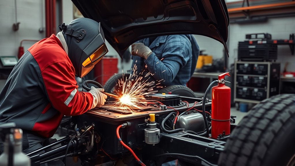
Inspect both sides of the repair and every connected cavity for fuel tanks, fuel lines, vapor lines, brake lines, insulation, carpeting, foam, seam sealer, adhesive, undercoating, sound deadener, and trim. Sparks can travel through openings, while heat can move through a panel and ignite material on the opposite side.
Follow this preparation sequence:
- Locate the fuel tank, filler neck, fuel lines, vapor lines, brake lines, and high-voltage components.
- Remove combustible trim, foam, sealers, adhesives, and loose debris from the required area.
- Protect glass, paint, upholstery, wiring, and nearby surfaces with approved welding blankets or shields.
- Keep a suitable fire extinguisher ready for immediate use.
- Provide ventilation and confirm that no flammable or explosive vapor is present.
- Assign a fire watch when the work conditions require one.
- Inspect hidden cavities and the back of the panel during pauses and after the weld.
Review these angle-grinder spark and fire precautions before grinding near trim, insulation, fuel-system parts, or hidden cavities.
OSHA’s hot-work requirements state that where a fire watch is required, it must continue for at least 30 minutes after welding or cutting to detect possible smoldering fires. Local workplace rules, insurers, or the repair facility may require a longer period.
Warning: Do not weld near a fuel tank, fuel vapor, brake line, battery, hidden insulation, or sealed cavity until the area has been prepared under the OEM procedure. If you cannot remove or fully protect the hazard, stop the repair.
Follow OEM Welding Instructions
The vehicle maker decides where welding is allowed, which process to use, how many welds are required, and where sectioning may occur. Read the complete body-repair procedure before cutting or preparing the panel.
The specified process may include GMA/MIG welding, MIG brazing, squeeze-type resistance spot welding, plug welding, weld bonding, riveting, adhesive bonding, or a combination. Do not substitute a familiar process because it appears easier. Incorrect heat input can weaken high-strength steel, aluminum, adhesives, coatings, or an underlying structural part.
Confirm all of the following:
- Permitted sectioning locations
- Material type and thickness
- Approved welding or joining process
- Welder, wire, gas, electrode, and setting requirements
- Number, size, spacing, and location of welds
- Required test welds and destructive testing
- Adhesive, sealer, primer, and corrosion-protection requirements
- Electrical-isolation and component-removal instructions
- Required diagnostic scans, initializations, aiming, and calibrations
Correct joint design and fillet weld sizing matter, but automotive structural repair must follow the vehicle maker’s dimensions rather than a general fabrication rule.
Plasma cutting may be prohibited or restricted near vehicle structures, wiring, fuel systems, high-voltage parts, or heat-sensitive materials. Review the hazards in this guide to plasma-cutter safety and follow the manufacturer’s approved repair method. Also use a complete plasma-cutter PPE and setup checklist when that process is permitted.
Control Coatings, Fumes, and Heat
Paint, zinc coatings, seam sealer, adhesive, undercoating, and contamination can affect weld quality and create hazardous fumes. Remove coatings only from the areas specified by the repair procedure, use suitable ventilation, and wear the required respiratory, skin, eye, and face protection.
Do not casually heat or cut galvanized material. Review the health and process concerns in this guide to plasma cutting galvanized steel. Where zinc removal is required, use an approved method and follow safe practices for removing zinc coating before welding.
OSHA identifies welding fumes, ultraviolet radiation, burns, eye damage, and electrical shock as major welding hazards. Use local exhaust ventilation where needed and never weld in a poorly ventilated enclosed vehicle interior without an appropriate hazard assessment and controls.
Restore Corrosion Protection After Welding
Cleaning the clamp and weld areas removes factory coatings that protected the metal from corrosion. After the weld has passed inspection and cooled, restore the materials specified by the OEM. These may include weld-through primer, epoxy primer, seam sealer, undercoating, paint, cavity wax, or corrosion-resistant fasteners.
Do not apply a coating until the joint has been inspected and the surface has been prepared correctly. Keep coatings out of electrical connectors, ground-contact surfaces, drains, and moving parts unless the repair procedure directs otherwise.
Inspect the Vehicle After Welding
After the metal cools, inspect the repair area before reconnecting or powering the vehicle. Look at both sides of the panel and inside accessible cavities. Check for heat damage, smoldering material, melted wiring, disturbed connectors, grinding debris, loose grounds, damaged hoses, and changes to nearby mechanical parts.
Reconnect batteries, modules, SRS components, and high-voltage systems only in the sequence specified by the manufacturer. Complete every required initialization, relearn, bleed, programming, test, or calibration procedure.
Check Electronics and Wiring
Inspect nearby electrical parts in a consistent order:
- Confirm every disconnected connector is fully seated and locked.
- Check harness retainers, clips, grommets, conduit, and heat shields.
- Look for burned insulation, cuts, crushed wires, exposed conductors, or metal debris.
- Verify that battery terminals and required chassis grounds are clean and secure.
- Check fuses only with the correct test procedure and rating information.
- Turn the vehicle on while watching for smoke, heat, abnormal sounds, or warning messages.
- Test lighting, charging, steering assist, braking, restraints, infotainment, climate control, and other affected systems.
Do not assume a vehicle is safe because it starts and no warning light remains on. Some modules store faults without illuminating the dashboard, and some systems need a specific self-test, drive cycle, or calibration.
Scan for Hidden Damage
Use the OEM-required scan tool and method. Where a full-system post-repair scan is required, scan every accessible module rather than checking only engine codes. Compare the result with the saved pre-repair report.
- Record all post-repair DTCs before clearing anything.
- Identify codes that were present before the repair.
- Investigate new codes, failed communications, implausible data, and voltage-history faults.
- Repair the underlying cause before clearing a code.
- Repeat the scan after repairs and required drive cycles.
- Complete all OEM-required programming, initialization, aiming, and ADAS calibration.
- Save the final report with the repair documentation.
OEM scanning requirements vary. For example, current collision-repair positions summarized by I-CAR include pre- and post-repair scanning requirements from manufacturers such as Ford and Lincoln, Honda and Acura, and General Motors.
Note: A diagnostic scan does not prove that every wire, module, restraint, or ADAS feature is physically undamaged. Combine scanning with visual inspection, functional testing, and every OEM-required calibration.
What to Do If You Welded With the Battery Connected
Do not assume that every module is damaged, but do not ignore the risk. Stop welding and document what happened, including the weld location, work-clamp location, welding process, and which vehicle systems were powered.
- Turn off the welder and vehicle, then follow the OEM shutdown procedure.
- Check the work-clamp path for bearings, hinges, cables, modules, or wiring that may have carried current.
- Inspect the weld area and nearby harnesses for heat, spatter, and physical damage.
- Do not erase codes or disconnect modules before recording their current state unless immediate safety requires isolation.
- Run an OEM-capable full-system scan where appropriate.
- Check battery voltage, charging operation, grounds, warning lights, communications, and affected safety systems.
- Investigate every new fault before returning the vehicle to service.
Intermittent communication problems, sensor readings that jump, repeated low-voltage codes, warning lights, a no-start condition, or a module that will not communicate require proper diagnosis. Replacing an ECU without testing its power, grounds, network circuits, and connectors can waste money and leave the actual fault in place.
Products Worth Considering

[Easy to Use—Work Out of the Box] + [FOXWELL 2026 New Version] FOXWELL NT604 Elite scan tool is the 2026 new version from FOXWELL, designed for car owners who want to figure out the cause of issues before fixing car problems by scanning common systems like ABS, SRS, engine, and transmission. The NT604 Elite obd2 scanner diagnostic tool comes with the latest software—no need to waste time downloading software first. Plug the scanner into the OBDII port with OBDII cable to start the diagnosis.

Multi-Functions - Practical Multi-Functions OBD2 code reader features built-in OBD2 DTC lookup library, which help you to determine the cause of the engine light, read code, erase code, view freeze frame, I/M ready, vehicle information, data flow, real-time curve, get vehicle speed information, calculate load value, engine coolant temperature, get engine speed.

【Diagnose Check Engine Light in Seconds – No Mechanic Needed】The FOXWELL NT301 OBD2 scanner instantly reads & clears engine fault codes (DTCs) with one click. Simply plug into the 16-pin DLC port, turn ignition on, and get accurate results within seconds—No prior car knowledge required. Save hundreds on dealership fees by knowing exactly what’s wrong before you visit a shop. The #1 choice car scanner for DIYers and car owners who want to take control of their vehicle’s health
Common Mistakes That Put Car Electronics at Risk
- Starting without OEM repair information: You may use the wrong joining process, isolation method, or sectioning location.
- Skipping the pre-repair scan: You lose the baseline needed to distinguish old faults from repair-related faults.
- Using one universal battery procedure: Vehicles differ in battery count, shutdown time, SRS storage, backup power, and high-voltage isolation.
- Clamping too far from the weld: This includes more of the vehicle in the welding circuit.
- Clamping over paint, rust, or sealer: Contamination raises resistance and weakens the return connection.
- Clamping to a lift, axle, spring, or engine: Current may cross bearings, joints, or unrelated components.
- Routing leads over electronics: Large cable loops and close routing can increase unwanted electrical coupling.
- Leaving modules or wiring inside the heat zone: Electrical isolation does not prevent melting or spatter damage.
- Relying only on a battery surge protector: It cannot fix an unsafe work-clamp path or replace OEM isolation.
- Ignoring hidden foam and sealer: Material inside a cavity may ignite after the visible weld has ended.
- Clearing codes without recording them: You destroy evidence that can help identify when and where a fault began.
- Skipping corrosion protection: Bare repair areas can rust even when the weld itself is sound.
Safe automotive welding depends on the complete repair process, not only the appearance of the finished bead.
Pre-Welding Safety Checklist
- Obtain the OEM repair procedure for the exact vehicle, material, and repair location.
- Confirm that welding and sectioning are permitted.
- Identify the approved process, equipment, wire, gas, weld pattern, and heat limits.
- Run and save the required pre-repair diagnostic scan.
- Turn the vehicle off and complete the specified module shutdown period.
- Disconnect and isolate the required low-voltage batteries, backup supplies, modules, SRS parts, and high-voltage system.
- Locate ECUs, sensors, harnesses, airbags, fuel lines, vapor lines, brake lines, and HV parts near or behind the weld.
- Remove or shield wiring, modules, glass, trim, insulation, foam, adhesive, sealer, and other heat-sensitive material.
- Remove fire hazards and keep a suitable extinguisher ready.
- Provide ventilation and use the correct helmet, eye protection, gloves, clothing, hearing protection, and respiratory protection.
- Clean the work-clamp point to bright bare metal.
- Place the work clamp close to the weld and preferably on the same panel.
- Confirm that current will not pass through bearings, hinges, axles, springs, cables, wiring, or modules.
- Route outgoing and return leads together and away from vehicle electronics.
- Perform the required test weld and verify the equipment settings.
- Monitor the back of the panel and hidden cavities while welding.
- Maintain the required post-weld fire watch.
- Inspect the weld, wiring, connectors, grounds, coatings, hoses, and hidden areas.
- Restore seam sealer, primer, coating, cavity protection, and corrosion protection.
- Reconnect systems in the specified order and complete all required relearns.
- Run the post-repair scan, functional tests, programming, aiming, and calibration required by the OEM.
Sources
- I-CAR: Removing Electronic Parts When GMA Welding — work-clamp placement, battery-cable isolation, cable routing, and nearby electronic-component removal
- I-CAR: Vehicle Protection When Welding — protection of wiring, modules, foam, sealer, glass, trim, and nearby vehicle components
- Tesla Collision Repair Procedures — electrical isolation and structural-welding restrictions for an EV
- OSHA: Welding, Cutting, and Brazing Hazards — fumes, UV radiation, burns, eye damage, electrical shock, and PPE
- OSHA 29 CFR 1910.252 — hot-work fire prevention, extinguishing equipment, and fire-watch requirements
- NHTSA-Hosted Manufacturer Service Bulletin — example manufacturer instructions for battery isolation, electronic-component disconnection, and work-clamp placement
Frequently Asked Questions
Will welding on a vehicle damage electronics?
It can. Electronic damage is more likely when the battery and required systems are not isolated, the work clamp is far from the weld, current crosses wiring or mechanical components, or modules remain close to heat and spatter. Following the vehicle maker’s procedure greatly reduces the risk.
Should you disconnect the battery when welding on a car?
Usually, but follow the exact OEM procedure. General GMA welding guidance often calls for disconnecting and isolating both conventional battery cables, negative first. Some vehicles also require backup-battery, module, SRS, low-voltage, or high-voltage isolation.
How long should you wait after disconnecting the battery?
Use the interval stated in the vehicle’s service information. There is no safe universal waiting time for every battery, SRS system, module, hybrid, or EV. Begin disconnecting components or welding only after the required shutdown and isolation procedure is complete.
Can welding damage an ECU even if the battery is disconnected?
Yes. A battery disconnect reduces risk but does not correct a poor work-clamp path, protect a nearby ECU from heat, or isolate every backup or high-voltage system. Correct clamp placement, cable routing, component removal, shielding, and OEM isolation instructions still matter.
Where should the ground clamp go when welding on a car?
Place the welding work clamp as close to the weld as practical on clean, bare metal and preferably on the same panel or component. Avoid any position that sends current through bearings, hinges, axles, springs, cables, wiring, modules, or unrelated body sections.
Do you need to disconnect the ECU or alternator before welding?
Only follow the vehicle maker’s instructions. Some repairs require specific modules, sensors, alternator connections, or other equipment to be disconnected or removed. I-CAR’s general GMA guidance recommends removing sensitive electronics when welding within 300 mm, but an OEM may specify another distance or procedure.
Will a battery surge protector make welding safe?
No device makes an unsafe setup safe. A surge protector cannot shorten the welding-current path, stop current from crossing a bearing, protect wiring from heat, disable a high-voltage battery, or replace the OEM battery and module-isolation procedure.
What should you do if you welded with the battery connected?
Stop, document the weld and clamp locations, inspect the current path and nearby wiring, and run the appropriate full-system diagnostic scan before clearing codes. Investigate new communication, voltage, sensor, restraint, ABS, steering, or ADAS faults before returning the vehicle to service.
Can welding shorten a welder’s life?
Repeated uncontrolled exposure to welding fumes, ultraviolet radiation, noise, heat, electrical hazards, and awkward work can harm long-term health. Proper ventilation, process controls, training, suitable PPE, hygiene, and medical monitoring where required can reduce occupational exposure.
How do you prevent electrical shock when welding?
Keep equipment dry and maintained, inspect electrode holders and cables, replace damaged insulation, wear dry welding gloves and protective clothing, avoid wet or conductive surfaces, follow the welder manufacturer’s instructions, and disconnect input power before servicing equipment. Never use your body to complete the circuit.
Conclusion
Protecting car electronics during welding requires more than disconnecting a battery. Read the vehicle-specific repair information, record the required pre-repair scan, isolate every specified power system, and place the welding work clamp beside the repair on clean metal. Keep current, heat, sparks, fumes, and grinding debris away from wiring, modules, fuel-system parts, bearings, and hidden combustible material.
After welding, maintain the required fire watch, inspect both sides of the repair, restore corrosion protection, reconnect systems in the proper order, and complete the OEM-required diagnostic scan, initialization, programming, aiming, and calibration. When the current path and repair process are properly controlled, the risk of hidden electronic damage is much lower.