
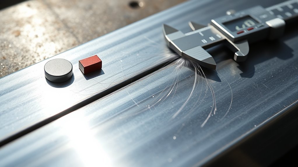
You can check basic weld quality without sending every sample to a laboratory, but you must separate practice feedback from formal acceptance. Start by identifying the drawing, welding procedure, code, or other criteria that define an acceptable weld. Then inspect the work before, during, and after welding. Use destructive tests only on representative coupons, and use qualified inspection whenever failure could injure someone or damage property.
Quick Answer
To test weld quality without a lab, clean the weld, inspect it under bright light, measure its size and profile, and check for cracks, undercut, overlap, porosity, and poor tie-in. Use bend, break, or macro-etch tests only on practice coupons. Use qualified inspection for structural, pressure, lifting, or vehicle work.
Key Takeaways
- Define the acceptance criteria before judging a weld. A visible discontinuity is not automatically acceptable or rejectable without a governing standard.
- Inspect the joint before welding, monitor important conditions during welding, and examine the completed weld after it cools.
- Visual inspection and measurement are the best first checks, but they cannot prove that the weld is internally sound.
- Liquid penetrant testing finds surface-breaking indications; magnetic particle testing is limited to suitable ferromagnetic materials and surface or near-surface indications.
- Bend, fillet-break, nick-break, and macro-etch tests are useful learning tools when performed on representative coupons you can destroy.
At a Glance
| Time Required | About 5 to 15 minutes for a basic visual check; longer for coupon preparation, penetrant testing, bend testing, break testing, or macro-etching |
| Difficulty | Beginner for basic visual checks; intermediate for representative coupon tests; professional qualification may be required for code work |
| Tools Needed | Bright light, wire brush, compatible cleaner, inspection mirror, magnifier, weld gauge, calipers, straightedge, marker, camera, and test-specific equipment when appropriate |
| Cost | Low when you already own inspection tools; varies for commercial penetrant products, MT equipment, cutting and polishing supplies, or professional NDT services |
Warning: Do not rely on garage testing to accept roll cages, trailer hitches, vehicle frames, suspension parts, lifting points, pressure vessels, boilers, structural steel, public handrails, or any weld controlled by a code, engineer, insurer, employer, or customer specification. Use the required welding procedure, acceptance criteria, and qualified inspection.
Define What an Acceptable Weld Means
Do not decide that a weld “passes” only because the bead looks smooth. Welding inspection determines whether the work meets the acceptance criteria in a drawing, welding procedure specification, code, standard, contract, or other controlling document. The AWS guide for visual weld examination recommends defining those criteria before welding begins.
A discontinuity is an interruption or irregularity in the material or weld. It becomes a rejectable defect only when it exceeds the applicable acceptance limit. Different projects can allow different amounts of undercut, porosity, reinforcement, concavity, or other conditions. There is no single garage rule that applies to every material and joint.
For practice work without a governing code, write down a comparison target before you start. You might require a consistent bead, full tie-in at both toes, no visible cracks, no visible overlap, the intended fillet size, and a coupon result that improves over your previous sample. Call this a practice target, not certification.
Note: The newest edition of a welding standard does not automatically govern an existing project. Use the edition named by the drawing, contract, engineer, employer, or authority having jurisdiction.
Visual Inspection: Your First Step in Weld Quality Assessment
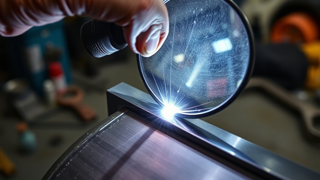
Visual inspection is usually the first weld-quality check because it is quick, inexpensive, and does not damage the part. The American Society for Nondestructive Testing describes visual testing as a method used to identify visible surface conditions and verify dimensions or conformance to specifications. Magnifiers, mirrors, borescopes, cameras, gauges, and controlled lighting can extend what you can see.
Visual examination should not begin only after the bead is finished. It is most effective when you inspect the work before welding, monitor important conditions during welding, and inspect the completed joint afterward.
Inspect Before Welding
Many weld problems begin with preparation or setup. Before striking an arc, check:
- Material: Confirm the base metal type and thickness instead of assuming two similar-looking pieces are identical.
- Joint preparation: Check the bevel, root face, root opening, alignment, backing, and access for the electrode or torch.
- Surface condition: Remove oil, paint, moisture, scale, heavy rust, coatings, and other contamination from the weld zone.
- Consumables: Confirm the filler classification, wire or rod diameter, condition, storage, and compatibility with the base metal.
- Machine setup: Verify polarity, voltage, amperage, wire speed, gas type, gas flow, and any required pulse or inductance settings.
- Tacks and fit-up: Check tack quality, joint restraint, distortion risk, and whether clamps block access or gas coverage.
- Temperature: Follow any specified preheat, interpass, or heat-input requirements.
- Environment: Control rain, moisture, wind, drafts, and temperatures that could affect the process.
Inspect During Welding
During welding, watch for conditions that may become buried after the next pass:
- Stable arc behavior and consistent wire feeding
- Correct travel angle, work angle, arc length, and stickout
- A puddle that reaches both sides of the joint
- Adequate shielding without drafts or a blocked gas nozzle
- Complete slag removal and cleaning between passes
- Proper bead placement and tie-in between adjacent passes
- Filled craters and controlled starts, stops, and restarts
- Specified interpass temperature and welding sequence
Understanding proper welding technique helps you connect a visible bead condition to changes in travel speed, angle, stickout, shielding, and heat input.
Post-Weld Visual Inspection Workflow
- Let the weld cool safely. Do not handle, clean, or measure hot metal without suitable tools and protection.
- Clean the surface. Remove slag, soot, loose oxide, spatter, oil, developer residue, paint, and grinding dust that could hide an indication.
- Use strong, directed light. Move the light across the bead from different angles so fine cracks, undercut, and overlap cast visible shadows.
- Inspect the full weld length. Include the toes, face, root when accessible, starts, stops, tie-ins, craters, tack locations, and heat-affected zone.
- Check the bead profile. Look for abrupt changes in width, height, reinforcement, concavity, convexity, or wet-out.
- Measure the weld. Use a suitable gauge, calipers, and a straightedge instead of estimating the size by eye.
- Mark every indication. Circle its location with a marker and note the distance from a repeatable reference point.
- Compare it with the acceptance criteria. Do not invent a pass limit after finding a flaw.
- Photograph and record the result. Include a ruler or gauge in the image when scale matters.
How to Use Basic Weld-Measuring Tools
A fillet weld gauge can compare the weld’s leg size and profile with a known dimension. Place the gauge against clean base-metal surfaces, not on spatter, scale, or a rounded edge. Check both legs because an unequal fillet can look larger than its effective size.
A multipurpose weld gauge may also measure reinforcement, undercut depth, misalignment, or fillet convexity, depending on its design. Calipers help compare bead width, plate thickness, and repeated locations. A straightedge can reveal distortion, high reinforcement, and misalignment across a butt joint.
Do not force a gauge against an irregular surface or round a reading in the direction that makes the weld pass. Record the actual measurement, tool used, location, and applicable limit.
Pro Tip: Photograph every practice weld before grinding, bending, or breaking it. Label the photo with the coupon ID, material, thickness, joint, process, position, polarity, filler, gas, voltage, amperage, wire speed, and any setting you changed.
What Home Weld Testing Can and Cannot Prove
Home testing is useful for improving technique, comparing settings, finding obvious surface conditions, and deciding whether a practice coupon deserves closer examination. It can show that a bead is undersized, that a crater contains a crack, or that a broken T-joint has an obvious unfused area.
It cannot prove that a finished weld meets a structural code. It cannot guarantee fatigue life, impact toughness, tensile strength, corrosion performance, or internal soundness. A small coupon also represents only the material, position, preparation, parameters, and location that you actually tested.
Visual testing is limited to accessible surfaces. Liquid penetrant testing finds discontinuities open to the surface. Magnetic particle testing finds surface and near-surface indications in suitable ferromagnetic materials. Internal discontinuities may require professional ultrasonic, radiographic, or other examination.
| Situation | Useful First Check | What It Does Not Prove |
|---|---|---|
| Completed noncritical shop part | Visual inspection and dimensional measurement | Internal fusion, fatigue life, or code compliance |
| Clean, nonporous material with a suspected surface crack | Liquid penetrant testing when compatible with the material and finish | Sealed or deep subsurface discontinuities |
| Ferromagnetic steel with a suspected surface or near-surface crack | Qualified magnetic particle testing | Deep internal soundness or suitability of nonmagnetic materials |
| Practice groove-weld coupon | Visual inspection followed by a controlled bend, nick-break, or cross-section check | Formal qualification unless specimen preparation and acceptance follow the required standard |
| Practice fillet-weld coupon | Visual inspection, fillet-break test, and macro-etch cross-section | Quality along the entire weld or in a different position |
| Structural, pressure, lifting, transport, or code-controlled weld | Specified professional inspection and testing | Nothing should be accepted from a garage appearance check alone |
Checks That Do Not Prove Weld Quality
- Tapping the weld: A clear or dull sound is not a dependable measure of fusion, penetration, or strength.
- Grinding the bead smooth: Grinding can hide surface profile problems without correcting an internal discontinuity.
- Looking for stacked-dime ripples: Ripple appearance is not a strength test and does not establish root fusion.
- Overloading the finished part: An uncontrolled load test can injure someone, damage the part, or leave hidden deformation and cracking.
- Improvised pressure testing: Never pressurize a homemade tank, pipe, or vessel as a casual weld test. Stored energy can cause a violent failure.
Note: A weld can look excellent and still contain internal lack of fusion, incomplete penetration, slag inclusion, or porosity. Treat appearance as the first screen, not the final word on a safety-critical joint.
Identifying Common Surface Defects: Key Indicators
Surface conditions can warn you that preparation, fit-up, settings, shielding, or technique need correction. Whether a condition is rejectable depends on the applicable criteria, but a crack or suspected lack of fusion should always trigger stop-work and further evaluation.
Porosity may appear as pinholes, rounded pits, or worm-like tracks. Common contributors include contamination, moisture, poor shielding, drafts, excessive arc length, damaged gas equipment, or unsuitable consumable storage.
Undercut is a groove melted into the base metal beside the weld toe that was not filled with weld metal. It can reduce the effective section and create a sharp stress concentration.
Overlap occurs when weld metal rolls onto the base metal without adequate fusion at the edge. It may look like a lip or shelf along the toe.
Cracks can appear in the crater, weld face, toe, root, tack, or heat-affected zone. Do not place a cracked critical part in service. Mark the crack, stop work, and obtain the required technical evaluation before attempting a repair.
Inadequate-fusion clues include cold-lap edges, a ropey bead, abrupt toes, poor sidewall tie-in, irregular wetting, and weld metal sitting high on the surface. These clues do not confirm the size of an internal flaw, but they justify closer testing and correction of the welding variables.
Regular defect assessment supports better welded-joint performance, but inspection findings must still be judged against the joint’s intended service and acceptance requirements.
Process-Specific Clues
| Process | Clues to Inspect | Likely Areas to Review |
|---|---|---|
| MIG or GMAW | Porosity, cold lap, irregular bead width, excessive spatter, burn-through, or poor start-stop tie-in | Gas coverage, polarity, contact-tip condition, wire feed, voltage, travel speed, stickout, and joint cleanliness |
| Flux-core or FCAW | Slag lines, trapped slag between passes, worm tracks, undercut, excessive reinforcement, or poor toe fusion | Travel direction, electrode angle, interpass cleaning, voltage, wire speed, stickout, and shielding requirements |
| Stick or SMAW | Slag inclusion, arc strikes, undercut, porosity, crater defects, excessive convexity, or incomplete tie-in | Electrode condition, amperage, arc length, manipulation, restart cleaning, angle, and pass placement |
| TIG or GTAW | Oxidation, tungsten inclusion, crater cracking, underfill, poor root profile, or contamination | Gas coverage, purge quality, tungsten condition, filler cleanliness, heat input, arc length, and crater control |
Clean the weld, inspect it from more than one angle, measure what you can, compare it with defined criteria, and record what changed between one coupon and the next.
Simple Tests for Evaluating Weld Quality at Home
Split garage weld checks into two groups: nondestructive checks for parts you intend to keep and destructive tests for representative coupons you are prepared to scrap.
A coupon should match the real work as closely as practical. Use the same base metal, thickness, joint design, preparation, filler, process, position, parameters, shielding, number of passes, and cleaning method. A flat-position coupon does not show that you can produce the same result vertically, overhead, around tubing, or in a restricted joint.
Visual Inspection Techniques
Begin with the overall bead profile. Changes in width, reinforcement, or toe blending may show that travel speed, arc length, work angle, stickout, or heat input changed during the pass. A uniform bead is useful evidence of consistency, but it does not establish internal fusion.
Inspect both toes for undercut, overlap, sharp transitions, and incomplete tie-in. Check the root whenever it is accessible. Examine starts, stops, craters, restarts, and intersections between welds because local flaws often form in these areas.
Measure the weld instead of assuming a large bead is strong. Oversized welds can add heat, distortion, cost, and residual stress. Undersized welds may provide less effective throat area than the design requires.
Simple Destructive Tests
- Bend test: Prepare and bend a welded strip so the weld or heat-affected zone is placed in tension. Use the result to compare practice samples unless a specified standard controls the specimen and acceptance criteria.
- Fillet-break test: Break a representative T-joint or lap-joint coupon to expose the root and fracture surface.
- Nick-break test: Prepare notches as required by the chosen method, break the specimen, and inspect the exposed weld for visible porosity, slag, incomplete fusion, or incomplete penetration.
- Macro-etch test: Cut, prepare, polish, and etch a weld cross-section to reveal the fusion boundary, penetration profile, root shape, weld size, and heat-affected zone.
These tests do not replace a formal welding-procedure qualification or welder-performance qualification. Formal tests use specified materials, dimensions, extraction locations, fixtures, preparation methods, and acceptance criteria.
Defect Troubleshooting Table
| What You See | Possible Contributors | What to Check Next |
|---|---|---|
| Pinholes or worm tracks | Contamination, moisture, poor shielding, drafts, damaged gas equipment, damp consumables, or excessive arc length | Clean the joint, verify gas delivery, block drafts, inspect hoses and nozzle, use suitable dry consumables, and correct arc length |
| Groove beside the bead | Undercut associated with excessive heat, fast travel, long arc, incorrect angle, or poor puddle control | Verify parameters, shorten the arc when appropriate, correct the angle, and maintain controlled toe fill |
| Rolled or lipped bead edge | Overlap or cold lap associated with low heat input, poor angle, slow manipulation, or excessive deposition | Confirm the parameter range, clean to bright metal, correct the work angle, and avoid pushing metal ahead of an unfused puddle edge |
| Crack at a crater, toe, root, or heat-affected zone | Poor crater fill, restraint, unsuitable filler, hydrogen, contamination, hard microstructure, or cooling stress | Stop using the part, mark the crack, identify the cause, and obtain qualified repair guidance for critical work |
| High, ropey bead with poor wet-out | Insufficient heat input, excessive travel speed, poor angle, excessive stickout, or cold joint surfaces | Verify settings and polarity, clean the joint, correct stickout and angle, and practice steady travel on matched coupons |
| Slag line or trapped island between passes | Incomplete interpass cleaning, poor pass placement, narrow groove access, or incorrect travel angle | Remove all slag, improve access, place beads so the next pass reaches both edges, and avoid welding over visible residue |
| Hole, excessive root opening, or melted edge | Burn-through associated with excessive heat, slow travel, large root opening, poor fit-up, or insufficient backing | Correct fit-up, reduce heat input within the approved range, increase travel control, and use the specified backing or technique |
Liquid Penetrant and Magnetic Particle Checks
Two common surface-oriented nondestructive testing methods are liquid penetrant testing and magnetic particle testing. They do different jobs and are not substitutes for internal examination.
Liquid penetrant testing, also called PT or dye penetrant testing, uses a visible or fluorescent penetrant and a developer to reveal discontinuities that are open to the surface of a suitable solid, nonporous material. It does not reveal sealed subsurface flaws.
Magnetic particle testing, also called MT, magnetizes a sufficiently ferromagnetic part and applies fine magnetic particles. Particles collect where a surface or near-surface discontinuity creates magnetic flux leakage. Standard MT is generally unsuitable for aluminum and most austenitic stainless steels because they are not sufficiently ferromagnetic for the method.
Proper eye, hand, and respiratory protection also matters when you clean or grind a weld, use aerosol test products, or inspect with specialized lighting.
| Method | Best For | Key Limits |
|---|---|---|
| Visual Testing | Surface conditions, bead profile, dimensions, fit-up, toe blending, and accessible cracks | Cannot establish internal soundness and depends on access, surface condition, lighting, equipment, and examiner skill |
| Liquid Penetrant Testing | Fine surface-breaking cracks, seams, and open pores in clean, solid, nonporous materials | Cannot find sealed subsurface flaws; rough, porous, dirty, painted, or oily surfaces can produce poor or misleading results |
| Magnetic Particle Testing | Surface and near-surface discontinuities in suitable ferromagnetic materials | Requires suitable material, controlled magnetization, correct technique and interpretation, and sometimes demagnetization afterward |
Products Worth Considering

Made in United States

Standard grade kit

The Dye Penetrant Crack Finder Kit (For Cast Iron and Aluminum) is a simple 4 step process that eas
Basic Liquid Penetrant Workflow
- Confirm compatibility. Make sure the test products are approved for the material, temperature, surface condition, and intended service.
- Preclean the surface. Remove coatings, oil, grease, dirt, loose scale, slag, and cleaner residue without smearing contaminants into a suspected opening.
- Dry the area completely. Moisture or cleaner trapped in a discontinuity can prevent penetrant entry.
- Apply the penetrant. Cover the inspection area and allow the exact dwell time required by the product instructions.
- Remove excess penetrant correctly. Use the specified method without flushing penetrant out of a discontinuity.
- Apply the developer. Use the specified type and a controlled coating rather than a heavy, uneven layer.
- Inspect under the required light. Visible and fluorescent systems have different lighting requirements.
- Mark and photograph indications. Record their position, length, shape, and orientation before cleaning the surface.
- Evaluate against defined criteria. An indication is evidence to assess, not an automatic universal pass or fail.
- Post-clean the part. Remove residues when required by the product instructions or service conditions.
Magnetic Particle Testing Limitations
Do not assume that a can of particles or a portable yoke makes an inspection valid. The examiner must confirm the material is suitable, select a magnetization technique, establish adequate field strength and direction, apply the particles correctly, and distinguish relevant indications from geometry, surface condition, and nonrelevant magnetic patterns.
When the result affects public safety, code acceptance, customer work, or return to service, MT should be performed and interpreted by personnel qualified for the applicable written practice and procedure.
Note: PT and MT reveal indications. The applicable code, specification, procedure, or qualified evaluator determines whether an indication is relevant and whether it exceeds an acceptance limit.
Perform a Bend Test to Check Ductility
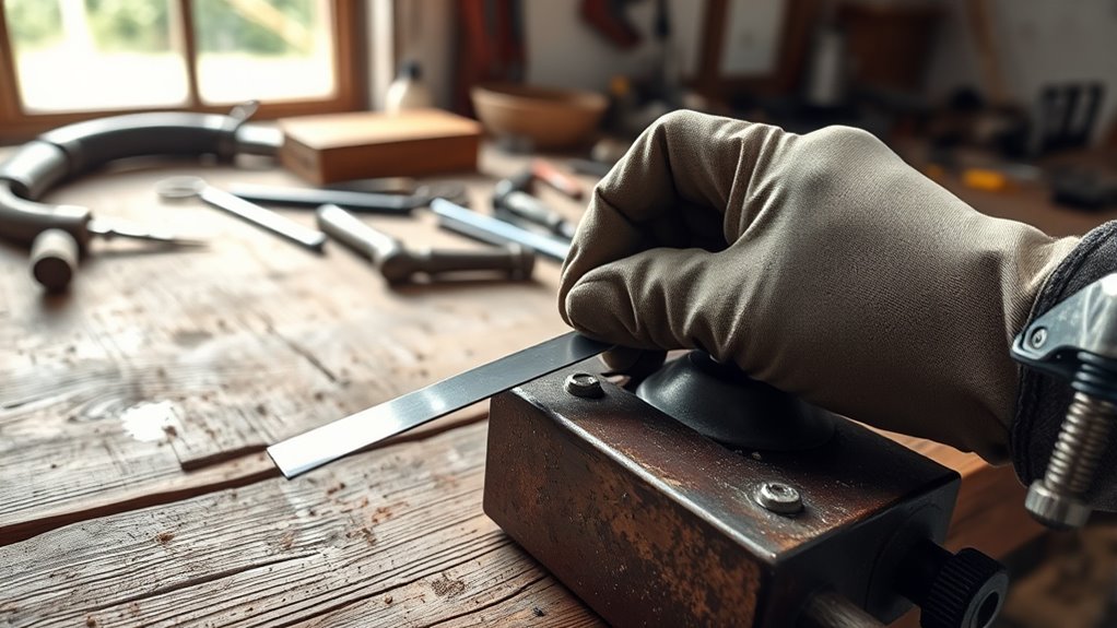
A bend test places a prepared weld coupon in tension so discontinuities may open on the convex surface. It is useful for comparing practice samples and for formal qualification when the specimen, fixture, bend radius, orientation, and acceptance criteria follow the required standard.
For a basic comparative shop test:
- Weld a representative coupon using the same joint, material, thickness, process, position, filler, and parameters you want to evaluate.
- Inspect and photograph the weld before cutting it.
- Cut the specimen through the welded joint at a planned location.
- Remove burrs and smooth sharp specimen corners without grinding away the area you intend to examine.
- Avoid deep preparation marks that can create an artificial notch.
- Use a sturdy, suitable fixture that supports the specimen and controls the bend.
- Keep your face, hands, and bystanders outside the release path.
- Bend the specimen steadily, then record where and how any opening formed.
A coupon that opens along an unfused root, sidewall, slag line, or large pore gives useful troubleshooting information. However, do not use “180 degrees with no visible cracking” or any other garage rule as a universal acceptance criterion. Material type, specimen thickness, bend radius, preparation direction, weld orientation, and the governing standard all affect evaluation.
This test can provide immediate feedback on joint preparation and weld cleanliness. Change one variable at a time so you can connect the next result to a specific adjustment.
Use the Fillet Break Test for T-Joint Evaluation
The fillet-break test is useful for a representative T-joint or lap-joint practice coupon. Breaking the coupon exposes the root and fracture surface, where you may see unfused areas, slag, porosity, or uneven penetration that were not visible from the outside.
Use this practice-coupon workflow:
- Prepare two clean plates with the same material, thickness, fit-up, and position as the work you want to practice.
- Weld the required side or sides using the settings and technique you want to evaluate.
- Let the coupon cool, then visually inspect, measure, photograph, and label it.
- Secure the coupon in a suitable vise or fixture rated for the force you will apply.
- Clear the area and place a face shield over safety glasses.
- Apply controlled force so the coupon opens at the fillet rather than flying unpredictably from the fixture.
- Inspect the exposed root and fracture surface for unfused areas, slag, pores, cracks, and inconsistent penetration.
- Record the result and compare it with your stated practice target or governing test procedure.
A fracture that exposes obvious root fusion provides better practice feedback than a joint that peels open along a smooth, unfused interface. It still does not establish a universal strength rating. Conditions such as porosity, cracks, weld size, and joint geometry must be evaluated in relation to the design and acceptance criteria.
Warning: A fillet-break test destroys the sample and can release sharp metal with considerable energy. Use it only on prepared coupons or scrap, secure the fixture, wear eye and face protection, and keep everyone outside the release path.
Explore Macro-Etching to See What’s Inside Your Welds
Macro-etching reveals a prepared cross-section of the weld. It can show the fusion boundary, penetration profile, root shape, weld size, heat-affected zone, and some visible internal discontinuities at the exact plane you cut.
A basic workflow for a practice coupon is:
- Cut squarely across the weld at the location you want to examine.
- Label the section so you know its orientation and coupon ID.
- Grind and sand the cut face flat through progressively finer abrasives.
- Clean the prepared surface without touching it with oily fingers.
- Use only an etchant and procedure confirmed suitable for the exact alloy.
- Apply, observe, neutralize, rinse, and dispose of the product as its instructions and safety data sheet require.
- Photograph the revealed cross-section with a scale and note the cut location.
The cross-section is a snapshot of one location, not proof that the full weld length has the same penetration or fusion. This method is useful when learning how fit-up, bevel angle, root opening, heat input, and pass placement affect the weld profile. For example, flux-core welding can provide substantial penetration, but poor cleaning or pass placement can trap slag.
Formal procedure qualifications may use specified macro-etch locations, preparation methods, and acceptance limits. A casual shop section should be described as a learning sample unless it follows the required procedure.
Warning: Do not improvise an etchant recipe or mix chemicals. Etchants and cleaners can burn skin, injure eyes, damage lungs, react with other products, and attack nearby surfaces. Use a verified commercial procedure, chemical-resistant gloves, eye protection, ventilation, and the exact safety data sheet. Send the sample to a metallurgical laboratory when you are unsure.
When Simple Tests Aren’t Enough: Exploring Nondestructive Testing Methods
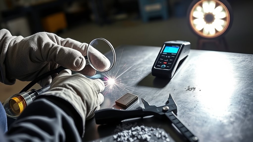
Visual inspection and simple coupon tests are useful starting points, but they may be inadequate when a weld carries significant risk. Professional nondestructive testing evaluates a component without destroying its intended usefulness.
- Visual Testing (VT): Evaluates accessible surfaces, dimensions, bead profile, alignment, and visible discontinuities.
- Liquid Penetrant Testing (PT): Reveals surface-breaking indications in suitable clean, solid, nonporous materials.
- Magnetic Particle Testing (MT): Reveals surface and near-surface indications in suitable ferromagnetic materials.
- Ultrasonic Testing (UT): Uses high-frequency sound and a qualified technique to detect and measure internal discontinuities.
- Radiographic Testing (RT): Uses ionizing radiation to produce an image of internal conditions and requires licensed, controlled radiation-safety practices.
Select the method according to the material, weld geometry, likely discontinuity orientation, access, surface condition, required sensitivity, service risk, and acceptance criteria. More testing is not automatically better if the chosen method cannot detect the flaw type or geometry of concern.
Strong ventilation and PPE practices also matter during welding, grinding, cleaning, chemical testing, and specimen preparation.
Products Worth Considering
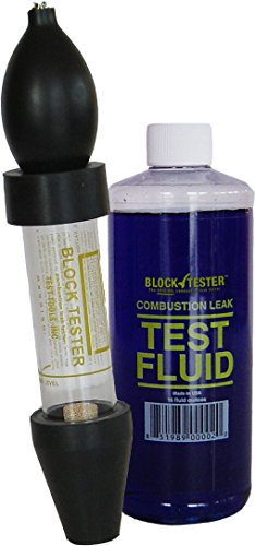
Complete Combustion Leak Test Kit: Includes fluid and all necessary components with nothing more to buy for immediate testing

FUN, FAST, AND ACCURATE! DETERMINES THE KARAT OF GOLD, SILVER, & PLATINUM JEWELRY IN SECONDS!

FAST DETECTION OF AIR & VACUUM LEAKS: Detect hidden air leak and vacuum leak issues before they lead to system failure or costly repairs. This ultrasonic leak detector helps locate tiny leaks in HVAC systems, compressed air lines and industrial equipment for faster diagnostics.
When to Call a Certified Weld Inspector
Call a qualified welding inspector, engineer, NDT technician, or other authorized professional whenever failure could injure someone, damage property, violate a code, or create significant liability. Examples include:
- Structural steel and public handrails
- Vehicle frames, suspension components, steering parts, and roll cages
- Trailers, hitch components, and towing attachments
- Cranes, hoists, lifting lugs, and overhead loads
- Pressure vessels, boilers, tanks, and pressurized piping
- Load-bearing brackets and machinery guards
- Customer work governed by drawings, contracts, procedures, or inspection plans
- Repairs involving unknown alloys, heat treatment, cracking, or repeated failure
You should also stop and get qualified help when a crack reappears, porosity continues after normal troubleshooting, penetration is inconsistent, or a repaired area has been heated repeatedly. Cutting and rewelding without identifying the cause can increase distortion, hardness, residual stress, and damage to the surrounding material.
The AWS Certified Welding Inspector program is one recognized route for welding-inspection qualification, but the project documents determine which credentials and inspection personnel are acceptable.
Documenting Your Findings: Creating an Effective Weld Log
A weld log turns trial and error into repeatable improvement. It lets you compare preparation, settings, technique, indications, and coupon results instead of relying on memory.
Key Log Components
- Identification: Date, project, coupon number, welder, drawing, procedure, and weld location.
- Base material: Alloy or grade when known, thickness, surface condition, and joint type.
- Consumables: Filler classification, diameter, batch or lot when relevant, shielding gas, and consumable condition.
- Machine settings: Polarity, voltage, amperage, wire speed, pulse settings, gas flow, travel speed, and heat-input controls when required.
- Preparation: Cleaning method, bevel, root face, root opening, alignment, backing, tacks, preheat, and interpass cleaning.
- Welding details: Position, angle, direction, number of passes, sequence, starts and stops, and environmental conditions.
- Inspection results: Visual findings, measurements, photos, PT or MT indications, bend results, break results, and macro-etch observations.
- Corrective action: What you changed and what happened on the next coupon.
Tracking flame adjustment, arc settings, shielding, and preparation details can reveal how small changes affect bead profile and visible fusion clues.
Consistent Entry Methods
Use the same format for every entry. A notebook works, but a spreadsheet makes it easier to sort by process, material, position, defect, and result. Name photographs with the coupon ID and important variables. For example, “Tjoint-1F-030wire-18V-250ipm-before-break” communicates more than “weldpic7.”
Do not record only “good” or “bad.” Write observable facts such as:
- No visible cracks after cleaning
- Fillet legs measured to the stated practice target
- Undercut indication marked 45 millimeters from the start
- PT indication measured and photographed before post-cleaning
- Bend coupon opened along an unfused root
- Fillet-break surface contained a slag line near the restart
- Macro-section showed incomplete fusion at one sidewall
Safety Precautions: Protecting Yourself While Testing Welds
Weld inspection and testing can expose you to hot metal, sharp edges, grinding particles, impact, stored mechanical energy, chemical products, ultraviolet light, noise, and welding fumes. Treat testing as controlled shop work rather than a casual check.
At minimum, use safety glasses and task-appropriate gloves. Add hearing protection when cutting, grinding, or hammering. Wear a face shield over safety glasses when a coupon, abrasive, wire, or chemical splash could strike your face. Clamp work securely and inspect the vise, press, fixture, hammer, grinder, wheel, and guards before applying force.
Use chemical-resistant gloves, splash protection, and ventilation for penetrants, developers, cleaners, and etchants. Read each safety data sheet. Keep incompatible products separate, control ignition sources around flammable aerosols, and dispose of residues according to the product instructions and local rules.
OSHA welding-safety guidance identifies hazards that include fumes, ultraviolet radiation, burns, eye injury, electric shock, cuts, and crushing injuries. The NIOSH welding-fume resource also explains that welding fumes may contain manganese and other metals and that inhaled manganese can affect the nervous system.
Keep a first aid kit, suitable fire extinguisher, and accessible eyewash nearby. Arrange the work so a broken coupon cannot strike you or another person. Never place your face, hands, or body in line with a loaded vise, press, bent specimen, or restrained plate.
Warning: Do not perform an improvised pressure, impact, lifting, towing, or overload test on a finished welded assembly. These tests can release dangerous stored energy and do not replace an engineered proof-test procedure.
Frequently Asked Questions
How do you check the quality of a weld at home?
Define your acceptance or practice criteria, inspect the joint before welding, monitor important conditions during welding, and clean the finished weld. Use bright light and a gauge to check cracks, porosity, undercut, overlap, crater fill, tie-in, bead profile, and weld size. Use destructive tests only on representative coupons.
Can a weld look good and still be bad?
Yes. A smooth, even bead can still contain incomplete penetration, lack of fusion, slag inclusion, or internal porosity. Visual inspection evaluates accessible surfaces and dimensions, so critical welds may require a specified professional NDT method.
Is dye penetrant testing good for welds?
Dye penetrant testing can reveal fine surface-breaking indications on suitable clean, solid, nonporous materials. It cannot detect sealed subsurface flaws, and rough, dirty, oily, painted, or porous surfaces can make the results difficult to interpret.
What is the easiest weld test for a beginner?
Start with visual inspection and measurement. A bright light, inspection mirror, magnifier, fillet weld gauge, calipers, and straightedge teach you to recognize bead-size problems, undercut, overlap, porosity, crater defects, and inconsistent profile without destroying the part.
Does passing a bend test prove that a weld is strong?
Not by itself. A garage bend test provides useful comparative feedback, but formal acceptance depends on the specified material, specimen dimensions, preparation, bend radius, fixture, orientation, and acceptance criteria. One specimen also represents only the location and conditions tested.
Can you test a weld by hitting it with a hammer?
A controlled fillet-break or nick-break test can provide useful information on a prepared coupon. Randomly striking a finished part does not establish weld quality and can create damage, hidden cracks, flying metal, or an uncontrolled failure.
When should I stop home testing and call an inspector?
Get qualified help when the weld is structural, load-bearing, pressure-related, tied to lifting or towing, used on a vehicle frame or suspension, controlled by a code, or made for a customer. You should also stop when cracks, unexplained porosity, or fusion problems keep returning.
Conclusion
Testing your weld quality without a lab begins with defined acceptance criteria, not appearance alone. Inspect the material and fit-up before welding, monitor the process while you weld, and examine the cleaned joint afterward with strong light and suitable measuring tools.
Use bend, fillet-break, nick-break, and macro-etch tests on representative practice coupons to learn how preparation and technique affect the inside of a weld. Use liquid penetrant or magnetic particle testing only within each method’s material and detection limits. When a weld is structural, load-bearing, pressure-related, tied to lifting or transport, or governed by a code, obtain the specified qualified inspection. Keep a detailed weld log so every test produces information you can use on the next joint.
Sources
- AWS B1.11M/B1.11, Guide for the Visual Examination of Welds — supports defined acceptance criteria, inspection timing, examination tools, and documentation.
- ASNT — Visual Testing — supports visual-testing principles, applications, equipment, and surface-inspection limits.
- ASNT — Liquid Penetrant Testing — supports PT principles, surface-breaking detection, nonporous-material requirements, and limitations.
- ASNT — Magnetic Particle Testing — supports MT use for surface and near-surface discontinuities in ferromagnetic materials.
- OSHA — Welding, Cutting, and Brazing Hazards and Solutions — supports welding, grinding, radiation, injury, PPE, and fume-safety guidance.
- NIOSH — Welding Fumes and Manganese — supports welding-fume composition and manganese-exposure health information.




