Welding 4130 chrome-moly tubing takes more than a neat-looking bead. The joint must match the tube grade, wall thickness, service load, and rules that govern the vehicle. Clean metal, close fit-up, suitable filler, controlled TIG heat, and a planned weld sequence all matter. This guide covers the full process for typical normalized 4130 automotive tubing while showing when you need a qualified welding procedure instead of a general shop method.
Quick Answer
To TIG weld 4130 chrome-moly tubing, confirm the material and applicable rules, notch the tubes for close contact, remove coatings and oil, and weld on DCEN with 100% argon. Use ER70S-2 or ER80S-D2 only when the approved procedure allows it, avoid forced cooling, and inspect every joint before service.
Key Takeaways
- Verify that the tube is normalized 4130 and follow the vehicle designer, sanctioning body, or qualified welding procedure.
- Aim for full, even tube-to-tube contact. Do not try to bridge a poor notch with extra filler and heat.
- ER70S-2 and ER80S-D2 are both established choices, but they do not produce identical weld properties.
- Thin-wall tubing below about 0.120 inch often does not need the usual 300°F to 400°F preheat, but this is a guideline, not a universal rule.
- Do not quench the weld or perform improvised torch stress relief. Use post-weld heat treatment only when an engineered procedure requires it.
At a Glance
| Time Required | About 1 to 3 hours for preparation, practice, welding, cooling, and visual inspection of a small assembly |
| Difficulty | Advanced; structural vehicle parts require proven TIG skill and an approved procedure |
| Tools Needed | DC TIG welder, argon regulator or flowmeter, torch with suitable tungsten, filler rod, tube notcher, clamps, abrasives, measuring tools, temperature crayons when preheat is specified, and full PPE |
| Cost | Variable; filler rod, argon, abrasives, solvent, and practice tubing are the main consumables when equipment and PPE are already available |
Warning: Roll cages, suspension parts, chassis structures, and other load-bearing vehicle parts can fail with little warning. Use the material grade, tube size, joint design, welding process, filler, inspection method, and fabricator qualifications required by the vehicle designer and governing rulebook. Do not use this general guide as a substitute for an approved welding procedure.
What’s in This Article
- Confirm the Material, Rules, and Weld Procedure
- Benefits of Using Chrome-Moly in Automotive Welding
- Key Properties of Chrome-Moly That Impact Welding
- Common Welding Challenges With Chrome-Moly Tubing
- What You’ll Need Before Welding Chrome-Moly
- Preparation Steps for Chrome-Moly Welding
- Step-by-Step TIG Welding Process for Chrome-Moly Tubing
- Select the Best Filler Metal for Chrome-Moly Welding
- Why Shielding Gas Matters in Chrome-Moly Welding
- Techniques for Effective TIG Welding of Chrome-Moly
- When Should You Consider Stress Relieving After Welding?
- How to Prevent Common Weld Defects in Chrome-Moly Tubing
- Best Practices for Welding Chrome-Moly Tubing
- Frequently Asked Questions
- Conclusion
Confirm the Material, Rules, and Weld Procedure
Start by confirming the alloy, condition, wall thickness, and intended service. This article focuses on normalized AISI 4130 tubing commonly used in motorsports and fabrication. It does not cover every chromium-molybdenum steel. Alloys such as 4140, heat-treated 4130, pressure-piping grades, and unknown salvaged tubing can require different preheat, filler, interpass, and post-weld heat-treatment controls.
Next, check the current rulebook or engineering drawing for the vehicle. A racing organization may specify tube dimensions, process, joint access, inspection, and welder qualifications. A street vehicle may also be subject to local construction and inspection rules. When a requirement conflicts with a general article, the approved drawing, welding procedure specification, and governing rules take priority.
A sound-looking bead cannot correct the wrong tube grade, an undersized joint, or a welding procedure that does not match the part’s service conditions.
Benefits of Using Chrome-Moly in Automotive Welding
Normalized 4130 tubing offers a useful combination of strength, toughness, and weldability. Designers can often meet a load target with thinner or smaller tubing than they would use with a lower-strength material, but the final weight and safety depend on the complete design rather than the alloy name alone.
Typical automotive uses include roll structures, chassis braces, space frames, suspension links, and mounts. These parts face different loads, so you cannot assume that one tube size or weld profile works for every application. Impact behavior, fatigue life, joint geometry, corrosion, and inspection access must all be considered.
TIG welding is popular for thin 4130 tubing because it gives you direct control of the arc, puddle, and filler addition. It also makes it easier to see the joint and limit unnecessary heat when your fit-up and technique are consistent.
Key Properties of Chrome-Moly That Impact Welding
4130 is a low-alloy steel containing chromium and molybdenum. These alloying elements help the steel respond to heat treatment and achieve higher strength than common low-carbon steel. That response is useful in service, but it also means the weld area can harden when the joint cools too quickly or receives excessive heat.
- Material condition matters: Normalized, annealed, and quenched-and-tempered 4130 do not share one universal welding procedure.
- Wall thickness matters: Thin tube sheds heat quickly, while thick or highly restrained joints can need preheat and tighter interpass control.
- Fit-up matters: A large or uneven gap increases filler volume, heat input, shrinkage, and the chance of undercut or incomplete fusion.
- Cooling rate matters: Water, compressed air, and other forced-cooling methods can raise cracking risk.
Control heat rather than trying to make the widest possible bead. The goal is complete fusion with a smooth transition into both tubes, not a large cap that hides the joint.
Common Welding Challenges With Chrome-Moly Tubing
The most common problems come from a combination of poor fit-up, contaminated metal, excess arc length, weak shielding, incorrect filler selection, and an unbalanced weld sequence. Each problem can affect strength and alignment even when the bead looks acceptable from one angle.
Heat-Affected Zone Issues
The heat-affected zone, or HAZ, is the base metal beside the weld that changed because of welding heat. A long arc, slow travel, repeated reheating, or an oversized bead can widen this zone. Fast cooling can produce a harder, less forgiving microstructure in susceptible joints.
- Keep the arc short and move as soon as the puddle has fused both edges.
- Use enough available amperage to form the puddle promptly instead of slowly soaking the tube.
- Do not weave widely on thin-wall tubing unless the approved procedure requires it.
- Allow the joint to cool naturally away from drafts and forced air.
Distortion During Welding
Every weld shrinks as it cools. On a tube assembly, that shrinkage can pull nodes out of position, change bracket angles, or twist the structure. A rigid fixture can hold alignment, but excessive restraint can also increase residual stress.
Use small, sound tacks at evenly spaced points, verify dimensions after tacking, and alternate weld locations so heat does not build on one side. Complete difficult or obstructed joints before adding tubes that block torch access.
Filler Material Selection
ER70S-2 and ER80S-D2 are both established choices for normalized 4130 tubing, but they serve different procedure goals. ER70S-2 is an undermatching filler that is widely used for ductility and crack resistance. ER80S-D2 provides higher-strength weld metal and is another common choice for sporting applications. Lincoln Electric lists both as options and notes that the correct method must be evaluated for the specific application.
Do not select matching 4130 filler simply because the base tube is 4130. Matching alloy filler generally needs stricter preheat and heat-treatment control. Lincoln’s current Techalloy 4130 product information specifies a 400°F preheat and reports its high mechanical properties after quenching and tempering, which is not the same as a typical as-welded roll-cage procedure.
What You’ll Need Before Welding Chrome-Moly
- DC-capable TIG welder with a foot pedal or other remote amperage control
- 100% argon cylinder, regulator or flowmeter, sound hoses, and a leak-free torch
- ER70S-2 or ER80S-D2 filler in the diameter required by the procedure
- 1/16-inch or 3/32-inch ceriated or lanthanated tungsten for common thin-wall work
- Gas lens and suitable cup when joint access or tungsten stickout makes them useful
- Tube notcher, files, deburring tools, dedicated clean abrasives, and a clean stainless brush
- Acetone or another approved non-chlorinated cleaner, lint-free wipes, and clean gloves
- Fixture, clamps, angle finder, squares, straightedge, and measuring tools
- Temperature crayons or a contact thermometer when preheat or interpass limits are specified
- Welding helmet, safety glasses, TIG gloves, flame-resistant clothing, closed footwear, hearing protection for grinding, ventilation, and suitable respiratory protection when the hazard assessment requires it
- Fire extinguisher and a cleared hot-work area
Note: Thoriated tungsten performs well on DC TIG, but it contains mildly radioactive thorium. Grinding can create inhalable dust. A non-radioactive ceriated or lanthanated electrode is the simpler default unless an approved procedure specifically requires thoriated tungsten.
Products Worth Considering
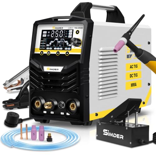
250A AC/DC TIG WELDING KIT — Includes the official SSIMDER foot pedal amp control, so you get hands-free current adjustment for aluminum, stainless steel, titanium, carbon steel, and copper, plus Stick mode, all in one 6 in 1 machine for garage and workshop projects

Wide Compatibility: This TIG welding foot pedal switch is specially designed for ARCCAPTAIN TIG welders, compatible with TIG200, TIG200P, TIG200P ACDC, TIG205 Pro, and TIG205P Pro. Note: Not compatible with MIG205MP.

Large LED Display: Features a large LED screen for enhanced visibility and a clear display of welding parameters and settings. Its intuitive interface ensures effortless operation, enabling precise welding of diverse metals
Preparation Steps for Chrome-Moly Welding
Preparation controls how much heat and filler the joint needs. Spend the extra time on the notch, alignment, and cleaning before you reach for the torch.
- Verify the tube. Check the material certificate, label, drawing, and wall thickness. Do not mix unknown tubing into a safety-critical assembly.
- Notch for full contact. Shape the tube so it follows the mating tube around the joint. A common thin-wall target is a near-zero, consistent gap; Lincoln’s 0.035-inch-wall example used 0.000 to 0.010 inch, but your procedure may specify another limit.
- Deburr both sides. Remove sharp edges, chips, and internal burrs that could trap contamination or melt into the puddle.
- Remove coatings and oxides. Clean far enough from the weld that paint, plating, marker residue, rust, and mill contamination cannot enter the arc.
- Degrease last. Wipe the joint and filler with an approved non-chlorinated cleaner and let it evaporate fully before welding. Never weld over wet solvent.
- Fixture and measure. Clamp the assembly without forcing a bad notch closed. Record critical dimensions before tacking.
- Tack at balanced points. Use at least four small tacks around a typical tube joint when access allows. Fuse each tack fully and remove any cracked or contaminated tack.
- Recheck alignment. Measure the assembly again before final welding. Correct a tack-stage problem now rather than trying to pull the finished weldment straight later.
Pro Tip: Cut several practice joints from the same tube heat and wall thickness. Practice the full notch, cleaning, tacking, welding, and sectioning process, not just a bead on flat scrap.
Step-by-Step TIG Welding Process for Chrome-Moly Tubing
- Confirm the procedure. Review the base-metal condition, filler, maximum gap, preheat, interpass limit, weld sequence, and inspection requirements.
- Set up DCEN. Use direct current electrode negative for steel. Start with the machine manufacturer’s recommendations and a maximum amperage suited to the actual wall thickness.
- Set argon flow. A typical starting range for small manual TIG work is about 15 to 20 CFH. Increase flow only when cup size, stickout, or joint geometry requires it. Excess flow can create turbulence and pull air into the shield.
- Prepare the tungsten. Grind a clean point lengthwise with a dedicated wheel. Keep the tip and gas-lens screen free from steel dust and filler spatter.
- Warm only when required. Thin-wall normalized 4130 below about 0.120 inch often does not need the usual 300°F to 400°F preheat, but the tube should be dry and at normal room temperature. Apply controlled preheat when the approved procedure calls for it.
- Start on a sound tack. Establish the puddle quickly, confirm fusion at both edges, and add filler to the leading edge without stabbing the tungsten.
- Keep a short arc. Hold the tungsten close enough to focus the arc without touching the puddle. Use a small torch angle so the gas remains over the molten and recently solidified metal.
- Travel around the joint. Reposition yourself or rotate the part so you can see the leading edge. Do not weld blind behind the tube.
- Finish the crater. Taper current while adding enough filler to leave the end full, not hollow. Keep the torch in place during post-flow.
- Balance the assembly. Move to another joint or opposite side before one area becomes overheated. Follow the planned sequence and any interpass limit.
- Cool naturally. Do not use water, compressed air, or a wet rag. Protect the hot joint from cold drafts and handling damage.
- Inspect before coating. Clean the joint and check the entire circumference under good light. Complete any required nondestructive examination before paint or powder coating.
Select the Best Filler Metal for Chrome-Moly Welding
Filler selection is a procedure decision, not a popularity contest. The best filler is the one that gives the required strength, ductility, crack resistance, and inspection performance in the actual joint and material condition.
Products Worth Considering

Premium Material: Crafted from high-grade stainless steel, ER308L rods ensure superior strength & durability for professional welding work

ER4043: Commonly referred to as “AlSi5", has a 5% silicon and is the oldest and one of the most widely used aluminum welding wires for general purpose applications.

Upgrade Packaging: These welding rods are packed in sturdy plastic packaging that is very waterproof and the welding wire will not get damp even if placed in water. This packaging can be reused
Recommended Filler Metals
| Filler | Typical reason to use it | Main caution |
| ER70S-2 | Common undermatching choice with good ductility and deoxidizers for clean, prepared 4130 tubing | Lower weld-metal strength than ER80S-D2; approval depends on the design and rules |
| ER80S-D2 | Common higher-strength option that can more closely approach normalized 4130 strength | Higher strength does not automatically make the joint safer; procedure, dilution, restraint, and ductility still matter |
| Matching 4130 filler | Specialized procedures that require matching chemistry and controlled heat treatment | Not a default filler for an as-welded automotive tube structure; it can create a hard, brittle joint without the specified thermal cycle |
Stainless filler is sometimes discussed for special dissimilar-metal or crack-control procedures, but it should not be presented as a general substitute. Use it only when a qualified procedure or engineer specifies the exact grade and service conditions.
Filler Metal Thickness
Choose a rod small enough to feed smoothly without chilling the puddle or forcing excessive heat. For common thin-wall tubing, 0.035-inch, 0.045-inch, and 1/16-inch filler are practical sizes. As a general starting point, do not use a rod larger than the tube wall unless the procedure requires it.
Use clean, straight filler and keep the hot end inside the shielding envelope. If you pull the rod into room air, oxidize it, and dip it back into the puddle, you can carry contamination into the weld.
Performance in Automotive Applications
Roll structures and chassis parts may face impact, bending, torsion, and millions of load cycles. Weld-metal tensile strength is only one part of performance. A reliable joint also needs sound fusion, suitable ductility, a smooth toe profile, correct tube geometry, and enough inspection access to find defects before service.
When joining 4130 to mild steel, do not assume the stronger filler is always correct. The procedure must account for both base metals, thickness mismatch, restraint, and the part’s failure mode.
Why Shielding Gas Matters in Chrome-Moly Welding
Use 100% argon for typical manual TIG welding of 4130 tubing. Argon protects the tungsten, arc, molten puddle, and hot weld metal from oxygen and nitrogen in the air.
A flow around 15 to 20 CFH is a common starting point for a standard cup or gas lens in a still shop. The correct flow depends on cup diameter, tungsten stickout, joint shape, and drafts. More gas is not always better because high flow can become turbulent.
- Check all hose, regulator, torch, and back-cap connections for leaks.
- Keep fans and open doors from blowing across the joint.
- Use enough pre-flow to clear the torch and enough post-flow to protect the hot tungsten.
- Keep the torch over the crater until post-flow ends.
- Back purging is not normally required for typical 4130 tube joints, but use it when the drawing, code, or qualified procedure specifies it.
Do not use a universal post-flow formula as a substitute for the welder manual and tungsten condition. If the tungsten turns blue, purple, or black after a weld, improve post-flow, gas coverage, or torch positioning before continuing.
Techniques for Effective TIG Welding of Chrome-Moly
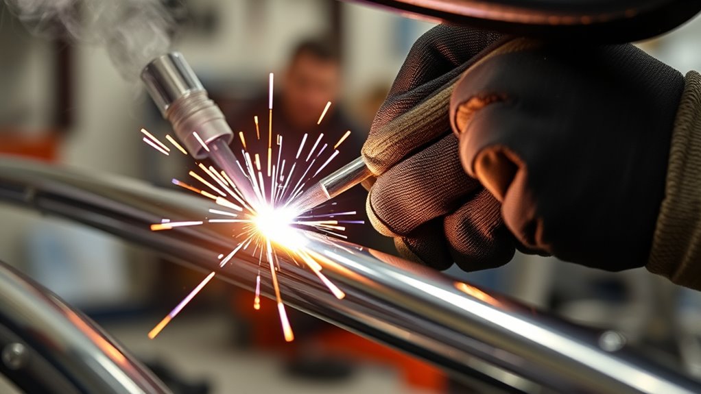
Good tube welding comes from consistent body position and visibility. Arrange the part so you can see the leading edge of the puddle and support both hands. When access becomes awkward, stop and reposition rather than stretching the arc.
TIG Setup Starting Points
- Polarity: DCEN
- Tungsten: 1/16-inch or 3/32-inch ceriated or lanthanated, ground to a clean point
- Shielding gas: 100% argon
- Gas flow: About 15 to 20 CFH as a starting range, then adjust for the cup and joint
- Arc length: As short as practical without touching the puddle
- Filler: ER70S-2 or ER80S-D2 in the size specified by the procedure
- Amperage: Based on the actual wall thickness, joint, machine, and operator; verify on matching scrap
The 20-to-40-amp and 9-to-12-volt values often copied online came from a Lincoln example for a 0.035-inch-wall, 90-degree tube joint. They are not universal settings for every tube under 0.120 inch. In manual TIG, arc voltage also changes with arc length, so focus on a short, stable arc and controlled heat rather than treating voltage as a fixed front-panel setting.
Torch and Filler Control
- Point the tungsten into the joint, not mostly at one tube.
- Keep the torch angle low enough to preserve shielding and avoid pushing the puddle ahead.
- Add small, regular dabs to the leading edge while both tube edges are molten.
- Do not wash a large puddle over unfused edges.
- Stop immediately after a tungsten touch. Regrind the tungsten and remove contamination from the weld before restarting.
Weld Sequence Around a Tube Joint
Many fabricators divide the circumference into manageable segments and move around the joint so they can maintain sight and hand position. The exact sequence depends on the fixture and access. Avoid repeated starts in one location, overlap each restart onto clean, sound weld metal, and keep craters full.
On a multi-tube node, plan which joints must be completed first. A tube added too early can block the cup, force a long tungsten stickout, and make full fusion impossible to verify.
When Should You Consider Stress Relieving After Welding?
Do not apply a generic 1,100°F torch stress-relief cycle to an automotive 4130 assembly. Local heating can create steep temperature differences, distortion, oxidation, and unknown mechanical properties. The FAA’s AC 43.13-1B states that members that depend on heat treatment for their properties should be heat treated after welding to the manufacturer’s specifications.
Typical normalized thin-wall sporting structures welded with an approved ER70S-2 or ER80S-D2 procedure often do not receive post-weld heat treatment. Thicker, highly restrained, heat-treated, or engineering-critical parts may require controlled preheat, interpass limits, furnace treatment, hardness checks, or other verification.
Use post-weld heat treatment only when all of these are known:
- The exact base-metal grade and starting condition
- The filler classification and weld procedure
- The required heating rate, soak temperature, soak time, and cooling rate
- The furnace or equipment’s temperature uniformity
- The final mechanical-property and inspection requirements
How to Prevent Common Weld Defects in Chrome-Moly Tubing
Inspect each weld as a complete joint, not just the section that is easiest to see. Use bright light, magnification when helpful, and a mirror or borescope for obstructed areas. A clean surface is necessary before visual or penetrant inspection.
| Problem | Likely causes | Correction |
| Porosity | Oil, paint, damp tube, gas leak, drafts, long arc, or filler leaving the gas shield | Remove the defect, reclean, fix shielding, and retest on scrap |
| Undercut | Excess heat, long arc, steep torch angle, fast travel, or poor filler placement | Shorten the arc, correct torch angle, and add filler at the toe while maintaining fusion |
| Lack of fusion | Low effective heat, filler placed on cold edges, poor access, oversized tack, or a gap hidden by the bead | Improve fit-up and access, establish fusion before adding filler, and section practice joints |
| Crater crack | Current stopped abruptly with an unfilled crater | Taper current and add filler before ending the arc |
| Tungsten inclusion | Tungsten touched the puddle or filler | Stop, grind out contamination as required, regrind the tungsten, and restart on sound metal |
| Distortion | Poor tack layout, one-sided heat buildup, oversized weld, or weak fixture | Balance the sequence, reduce unnecessary heat, and verify fixture support |
Note: Visual inspection cannot prove penetration, internal fusion, hardness, or fatigue life. Critical parts may require liquid penetrant, magnetic-particle testing, radiography, ultrasonic testing, hardness checks, destructive procedure coupons, or another method selected by a qualified inspector.
Best Practices for Welding Chrome-Moly Tubing
- Use traceable tubing and keep its grade and condition separate from mild-steel stock.
- Qualify your settings and technique on matching scrap before welding the assembly.
- Notch for close, even contact and never force a poor joint together with clamps.
- Clean with dedicated tools and an approved non-chlorinated solvent.
- Use DCEN, 100% argon, a short arc, and enough available amperage to form the puddle promptly.
- Choose ER70S-2, ER80S-D2, or another filler only through the applicable procedure.
- Keep the filler and hot tungsten inside effective gas coverage.
- Use balanced tacks and a planned weld sequence to control distortion.
- Do not quench, blow compressed air on, or improvise stress relief on the finished weld.
- Inspect before coating and document critical joints, repairs, filler lot, and welder identity when the job requires traceability.
Welding also creates arc radiation, hot metal, fire risk, and fumes. OSHA requires suitable ventilation or respiratory protection when unsafe contaminant levels can accumulate and specifically addresses chromium-bearing metals in enclosed spaces. Review the OSHA ventilation requirements for welding and keep combustibles away from the hot-work area.
Frequently Asked Questions
How do you weld 4130 chrome-moly tubing?
Confirm the material and governing procedure, notch the tubes for close contact, remove coatings and oil, tack the assembly in alignment, and TIG weld on DCEN with 100% argon. Use the specified filler, control arc length and heat, let the joint cool naturally, and complete the required inspection before service.
Do you have to TIG weld chrome-moly tubing?
No single process is mandatory for every 4130 application. TIG is common for thin automotive tubing because it gives precise control and a clear view of the joint. Oxyfuel and qualified wire processes may be acceptable in some designs, but the drawing, rulebook, and approved welding procedure decide what you may use.
Can you MIG weld a 4130 roll cage?
Only when the governing rules and a qualified procedure allow it. Some sanctioning bodies require TIG for 4130 structures or limit which processes may be used. Do not choose MIG simply because it is faster, and do not assume a mild-steel wire setting is suitable for a safety-critical chrome-moly cage.
Is chrome-moly steel hard to weld?
Normalized thin-wall 4130 is weldable, but it is less forgiving of poor material identification, bad fit-up, uncontrolled heat, and forced cooling than a casual mild-steel project. The welding becomes manageable after you use a repeatable procedure and prove it on matching practice joints.
Is ER70S-2 or ER80S-D2 better for 4130 tubing?
Neither filler is automatically better. ER70S-2 is a common undermatching choice with good ductility, while ER80S-D2 provides higher-strength weld metal. Use the filler required by the design, rulebook, or qualified procedure, then verify the result with practice coupons and the specified inspection.
Should you preheat 4130 before welding?
Thin-wall normalized tubing below about 0.120 inch often does not need the usual 300°F to 400°F preheat when it is dry and at room temperature. Thicker, cold, highly restrained, heat-treated, or critical parts may need controlled preheat. Follow the approved procedure instead of using wall thickness as the only decision.
Does 4130 tubing need post-weld stress relief?
Typical normalized thin-wall sporting structures often do not receive post-weld heat treatment when welded with an approved ER70S-2 or ER80S-D2 procedure. Heat-treated, thick, restrained, or specially engineered parts may need a controlled furnace cycle. Do not perform local torch stress relief unless the approved procedure defines it.
Do you need to back purge 4130 tubing?
Back purging is not normally required for typical open-root tube-to-tube 4130 joints, but it may improve internal oxidation control in some designs. Use it when the drawing, code, or qualified welding procedure requires it.
How do you inspect a chrome-moly weld?
Begin with a full-circumference visual inspection for cracks, porosity, undercut, overlap, incomplete fusion, crater defects, tungsten contamination, and poor bead transitions. Critical structures may also require penetrant, magnetic-particle, radiographic, ultrasonic, hardness, or destructive procedure testing selected by a qualified inspector.
Conclusion
Reliable chrome-moly welds begin before the arc starts. Confirm the tube and governing procedure, produce close fit-up, clean the joint and filler, and prove your setup on matching scrap. During welding, use DCEN, stable argon coverage, a short arc, controlled filler addition, and a balanced sequence.
ER70S-2 and ER80S-D2 are both valid procedure options for normalized 4130 tubing, but neither should be treated as a universal answer. The same caution applies to preheat and post-weld heat treatment. Follow the part’s actual thickness, condition, restraint, service load, and rules.
For any roll cage, suspension component, chassis structure, or road-safety part, use a qualified fabricator and the required inspection. A polished bead is not enough when the joint must protect people.
Sources
- Lincoln Electric: TIG Welding Chrome-Moly Tubing — thin-wall preheat guidance, filler choices, DCEN, argon, fit-up, and example weld parameters
- Lincoln Electric: Techalloy 4130 TIG Wire — matching 4130 filler requirements and heat-treated weld-metal properties
- Federal Aviation Administration: AC 43.13-1B, Chapter 4, Welding and Brazing — material identification, cleaning, inspection, filler compatibility, and manufacturer-specified heat treatment
- OSHA 29 CFR 1926.353 — ventilation, chromium-bearing metals, eye protection, and respiratory controls
- OSHA 29 CFR 1910.252 — hot-work fire prevention and cleaning of containers before welding
- ESAB: What Is Thoriated Tungsten Used For? — thoriated tungsten performance, grinding-dust risk, and non-radioactive alternatives