
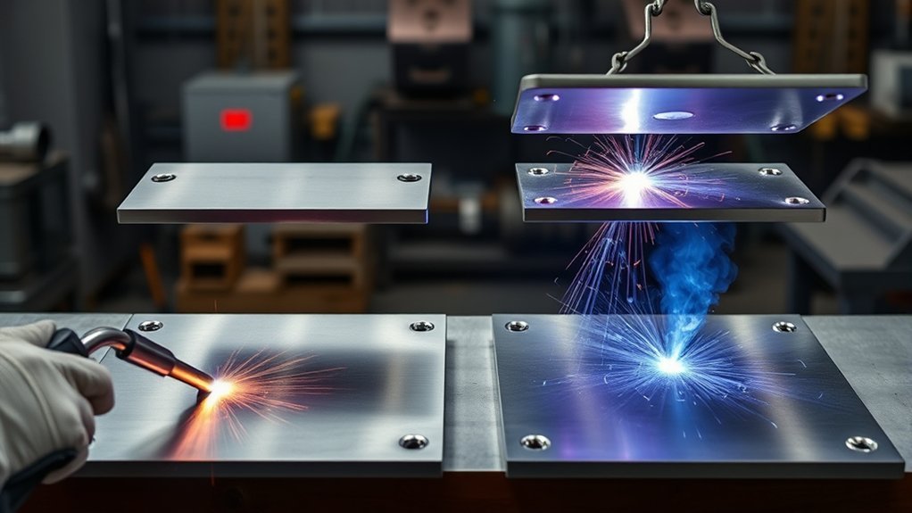
Welding position labels such as 1F, 2F, 3F, and 4F tell you how a fillet-weld test joint is oriented while it is welded. Welders also use the same labels as everyday shorthand for flat, horizontal, vertical, and overhead fillet welding. Knowing the code helps you picture the joint, predict how gravity will affect the puddle, and prepare the correct technique.
Quick Answer
1F means a flat fillet-weld test position, 2F means horizontal, 3F means vertical, and 4F means overhead. The number identifies the test position, while F identifies a fillet weld. In everyday shop talk, these codes are often used as shorthand for the matching production-welding orientation.
Key Takeaways
- 1F, 2F, 3F, and 4F are fillet-weld test-position designations commonly matched with flat, horizontal, vertical, and overhead welding.
- F means fillet; G means groove.
- Gravity has a greater effect as you move from flat work to vertical and overhead work.
- The position code does not set amperage, voltage, filler metal, preheat, or travel direction by itself; follow the welding procedure and consumable instructions.
- Overhead and out-of-position welding require suitable filler metal, full protective equipment, fire control, and effective fume ventilation.
At a Glance
| Time Required | About 5–10 minutes to learn the codes; hands-on mastery takes repeated practice. |
| Difficulty | 1F is usually the easiest to control; 4F is usually the most demanding. |
| Tools Needed | No tools to read the codes. Practice requires a suitable welder, approved filler metal, prepared scrap coupons, clamps, ventilation, and full welding PPE. |
| Cost | Free to learn; practice cost depends on equipment, coupons, consumables, gas, and protective gear. |
What’s in This Article
- What Do 1F, 2F, 3F, and 4F Mean?
- What’s the Difference Between F and G?
- The Four Basic Welding Positions
- When to Use Each Welding Position
- Flat Welding Position: 1F and 1G
- Horizontal Welding Position: 2F and 2G
- Vertical Welding Position: 3F and 3G
- Overhead Welding Position: 4F and 4G
- How Position Affects Settings and Filler Metal
- Plate vs. Pipe Position Codes
- Welding-Position Safety
- Practice Tips for Better Welds
- Common Mistakes to Avoid
- Frequently Asked Questions
What Do 1F, 2F, 3F, and 4F Mean?
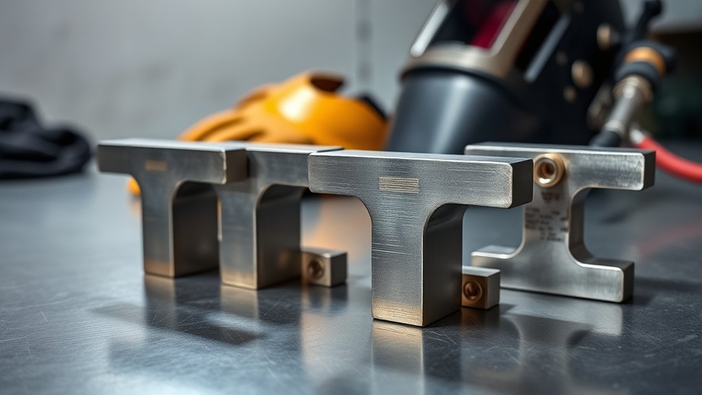
In the common American Welding Society system, 1F, 2F, 3F, and 4F identify fillet-weld test positions. The matching orientations are:
- 1F: flat fillet position
- 2F: horizontal fillet position
- 3F: vertical fillet position
- 4F: overhead fillet position
The formal distinction matters. AWS terminology treats 1F through 4F as welding test-position designations, while production welds are described as flat, horizontal, vertical, or overhead. In schools, shops, drawings, and job discussions, people often use the numbered labels as convenient shorthand for the matching orientation.
Note: A position code describes joint orientation and weld type. It does not, by itself, select the welding process, filler metal, voltage, amperage, preheat, travel speed, or acceptance criteria.
In 1F, gravity generally helps keep the molten weld pool in place. In 2F, the pool can sag toward the lower member. In 3F, the welder must control a puddle moving up or down a vertical joint. In 4F, the weld is deposited from below, so hot metal and slag can fall toward the operator.
Understanding the code helps you plan body position, access, work angle, travel angle, and puddle control. It also helps you read a test record or welding procedure, but the procedure and governing code remain the controlling documents.
Material preparation is separate from position. For example, cast iron may require a qualified preheat and cooling plan to reduce cracking, while many mild-steel practice coupons do not. Always follow the procedure for the material being welded.
What’s the Difference Between F and G?
F identifies a fillet weld. Fillet welds commonly join members that meet at an angle, including T-joints, lap joints, and corner joints. Their cross-section is often roughly triangular, although the final profile may be concave, flat, or convex.
G identifies a groove weld. A groove weld is made in a groove between workpieces. The edges may be square, beveled, V-shaped, U-shaped, J-shaped, or prepared in another approved form.
Therefore, 1F through 4F refer to fillet-weld test positions, while 1G through 4G refer to groove-weld test positions on plate or sheet. The position number may match, but the joint geometry and qualification requirements differ.
A groove weld is not automatically stronger than a fillet weld. Strength depends on the joint design, weld size, effective throat, penetration requirement, base metal, filler metal, workmanship, loading, and applicable code. Some groove welds require complete joint penetration; others are intentionally partial-joint-penetration welds.
Correct fillet-weld sizing is just as important as position. An undersized weld may not carry the design load, while an unnecessarily oversized weld can increase heat input, distortion, time, and consumable use.
The Four Basic Welding Positions
The four basic production-welding orientations are flat, horizontal, vertical, and overhead. Their names describe the position of the weld axis, weld face, and joint relative to gravity—not simply whether the welder is standing, sitting, or lying down.
Flat welding offers the most support for the puddle. Horizontal welding adds a downward pull across the bead. Vertical welding requires the welder to control upward or downward progression. Overhead welding places the puddle above the operator and demands strong control of fluidity, access, and falling spatter.
These principles apply to MIG, TIG, stick, flux-cored, and other processes, but the exact technique changes with the process and approved procedure. Oxy-fuel work also requires correct flame adjustment, which is separate from the position code.
Fillet Position Codes
Fillet position codes identify standard test orientations for fillet welds. For plate or sheet work, the familiar sequence is 1F, 2F, 3F, and 4F.
In 1F, the test assembly is arranged so the weld is deposited in the flat position. In 2F, the fillet is made in the horizontal position, often with a lower member supporting part of the puddle. In 3F, the joint is vertical. In 4F, the fillet is made from below the joint.
The code is useful only when read with the rest of the job information. A complete instruction may also identify the process, base metal, thickness, joint details, filler classification, shielding gas, electrical polarity, progression, preheat, interpass temperature, and inspection criteria.
Flat to Overhead
| Code | Common Meaning | How Gravity Affects the Puddle | Main Control Need |
|---|---|---|---|
| 1F | Flat fillet | Supports the puddle in the joint. | Maintain even work angle, travel angle, and speed. |
| 2F | Horizontal fillet | Pulls metal toward the lower member. | Prevent overlap at the lower toe and undercut at the upper toe. |
| 3F | Vertical fillet | Pulls the puddle downward during up or down progression. | Control heat, pause at the toes, and follow the approved progression. |
| 4F | Overhead fillet | Pulls molten metal, slag, and spatter toward the operator. | Keep the puddle manageable and protect against falling hot material. |
The code tells you where the test joint is positioned; the welding procedure tells you how that joint must be welded.
When to Use Each Welding Position
Use the flattest practical position when the design, fixture, and procedure allow it. Repositioning a part can improve access, deposition rate, visibility, and puddle control. Large or fixed assemblies, however, may force the welder to work horizontally, vertically, or overhead.
Typical examples include:
- 1F: bench fabrication, brackets, frames, and parts that can be rotated into the flat position.
- 2F: T-joints on upright members, beams, columns, and fixed assemblies.
- 3F: vertical seams on structural members, tanks, frames, and repairs where the work cannot be rotated.
- 4F: undersides of structures, equipment, bridge components, ceiling-level members, and fixed repairs.
Position alone does not determine whether a weld is acceptable for structural service. The joint must meet the drawing, welding procedure specification, applicable code, and inspection requirements.
Flat and Horizontal Use
Flat 1F work usually gives the welder a stable puddle, clear visibility, and room for a steady travel speed. It is a good starting position for learning work angle, arc length, electrode placement, and bead consistency.
Horizontal 2F work is more sensitive to gravity. The lower member can act like a shelf, but the puddle may still roll downward. A balanced work angle and suitable heat input help prevent excess buildup on the lower leg and undercut on the upper leg.
Both positions are common on plates, beams, frames, brackets, and shop-fabricated components. Practice should include checking both weld legs, the toes, the root, and the overall profile rather than judging quality from appearance alone.
Vertical and Overhead Use
Vertical and overhead welding are often called out-of-position welding. Gravity works against puddle placement, so the welder may need a smaller, faster-freezing puddle and more deliberate movement than in flat work.
For 3F, the welding procedure must state or permit the required progression. Vertical-up welding is common on thicker, load-bearing work because it can provide good sidewall fusion and penetration when performed correctly. Vertical-down welding travels faster and is often used on thinner material or approved applications, but it is not a universal substitute for vertical-up welding.
For 4F, position your body so you can complete the weld without moving directly under the path of falling spatter. Use only a filler metal and transfer mode approved for overhead welding, and keep the weld pool within the size and fluidity allowed by the procedure.
- Use 1F and 2F when the work can be placed flat or horizontal.
- Use 3F when the joint must be welded vertically.
- Use 4F when the joint must be welded from below.
- Practice each required position with the same process and progression used for the actual test or job.
Flat Welding Position: 1F and 1G
The flat position is usually the easiest orientation for learning puddle control. 1F identifies a flat fillet-weld test position, while 1G identifies a flat groove-weld test position.
Gravity supports the molten pool, which can make the bead easier to see and control. MIG, TIG, stick, and flux-cored processes may all be used in the flat position when the procedure, machine, and filler metal are suitable.
For a fillet weld, keep the work angle centered as required by the joint so heat reaches both members. For a groove weld, the correct angle depends on the groove shape, root opening, backing, and pass being deposited.
Flat welding is common in fabrication because large plates, frames, and structural components can often be positioned before welding. Process selection still depends on material type, thickness, joint access, production needs, and the approved procedure—including when welding thin automotive sheet metal.
Horizontal Welding Position: 2F and 2G
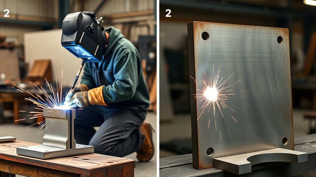
Horizontal welding requires steady control because gravity pulls the molten metal toward the lower side of the joint. 2F identifies a horizontal fillet-weld test position, while 2G identifies a horizontal groove-weld test position.
In 2F, a T-joint or similar joint often provides a lower shelf that supports part of the puddle. In 2G, the groove face lies on a vertical plane, so puddle balance can be more difficult.
Use the approved work angle and travel angle, watch both toes, and avoid making the puddle more fluid than the procedure allows. Proper cleaning and fit-up help reduce porosity, lack of fusion, slag entrapment, and an uneven bead.
- Watch how the puddle wets into the upper and lower toes.
- Keep arc length or contact-tip-to-work distance consistent.
- Maintain the travel speed specified or proven on a practice coupon.
- Adjust only within the procedure or manufacturer’s recommended range.
These techniques are common on beams, frames, and fixed structural components where the joint cannot be rotated.
Vertical Welding Position: 3F and 3G
The vertical position places the weld axis on an upright plane. 3F covers a vertical fillet-weld test position, while 3G covers a vertical groove-weld test position.
Vertical welding can progress upward or downward. The required direction depends on the process, filler metal, material thickness, joint design, and welding procedure. Do not change progression simply because one direction feels easier.
For many common mild-steel applications, vertical-up progression is used on thicker material and can provide stronger sidewall tie-in when performed correctly. Vertical-down progression moves faster and can reduce burn-through on thin material, but it often produces shallower penetration and may be prohibited by the governing procedure.
Gravity pulls the puddle down, so the welder may use controlled movement such as a small zigzag, triangle, or stepped pattern. The correct pattern is process- and joint-specific. Excessive weaving can increase heat input, trap slag, or create poor bead shape.
Flux-cored, stick, MIG, and TIG techniques differ. Use the settings and gun or electrode angles approved for the exact process and consumable.
Overhead Welding Position: 4F and 4G
The overhead position places the welder below the joint. 4F identifies an overhead fillet-weld test position, while 4G identifies an overhead groove-weld test position.
Both positions demand close control because gravity pulls the weld pool, slag, and spatter downward. A stable stance, clear travel path, suitable filler metal, and procedure-compliant settings are essential.
Warning: Overhead welding can expose you to falling molten metal, slag, sparks, fumes, ultraviolet and infrared radiation, electrical shock, and fire. Wear a welding helmet with the correct lens shade, safety glasses, flame-resistant clothing, leather gloves, hearing protection where needed, and protective footwear. Use effective ventilation and keep combustibles out of the hot-work area.
For many arc-welding processes, a short, controlled arc and a manageable puddle improve overhead control. However, the exact arc length, wire speed, voltage, amperage, and weave must follow the procedure and consumable manufacturer’s guidance.
- Set up the work area so you are not directly beneath the heaviest spatter path.
- Confirm that the filler metal is rated for overhead use.
- Complete a dry run to check reach, visibility, and cable movement.
- Keep the puddle small enough to control without exceeding the procedure.
- Inspect between passes and remove slag as required.
Overhead fillets and grooves may appear in bridge work, equipment undersides, ceiling-level repairs, and pipe or tube connections. Tight access and limited visibility make these welds more demanding.
How Position Affects Settings and Filler Metal
Welding position affects puddle behavior, but there is no single universal setting change for every process. A common mistake is to copy a flat-position setup into vertical or overhead work without checking the procedure.
Use this order of authority:
- Follow the welding procedure specification or approved job instructions.
- Confirm the filler metal’s position rating on the manufacturer’s data sheet or package.
- Use the machine manufacturer’s starting range for the process, wire or electrode size, material, and transfer mode.
- Verify on a prepared practice coupon before welding the actual part.
Out-of-position work often needs a puddle that freezes faster and remains easier to support. Depending on the process, this may involve lower heat input, a different transfer mode, a smaller electrode or wire, shorter passes, or a different travel speed. These are starting principles—not permission to override the procedure.
Short-circuit GMAW can help control heat on thin metal, but it is not automatically approved for every structural application or position. Preheat, interpass temperature, and postweld heat treatment are also material- and procedure-specific, not determined by the 1F–4F code.
Products Worth Considering


Plate vs. Pipe Position Codes
This article focuses on the familiar plate or sheet fillet positions 1F through 4F. Pipe and tube work introduces additional test arrangements and may use different numbers.
Common groove-weld pipe positions include 1G, 2G, 5G, and 6G. Fillet-weld tests on tube may include 1F, 2F, 4F, and 5F, depending on the governing code. “Rotated” positions mean the test piece turns so the weld remains in a controlled orientation; fixed positions require the welder to move around the joint.
Do not assume that passing one test qualifies every position, process, thickness, diameter, progression, backing condition, or joint type. Qualification ranges vary by code and test variables.
Note: A shop may casually call a production weld “3F” or “4F,” but a formal qualification record should be read according to the governing AWS, ASME, API, military, aerospace, or employer specification.
Products Worth Considering

Pipe Pit Welding Gauge

PASS X-RAY INSPECTIONS WITH CONFIDENCE: Designed to cut radiographic rejects by accurately measuring internal misalignment after fit-up. Delivering professional-grade precision up to ±0.001 inches, this gauge is NBS calibration capable, making it the trusted choice for Certified Welding Inspectors (CWI) and serious pipefitters.
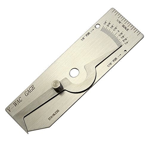
V-WAC Single Weld Gage
Welding-Position Safety
Safety requirements apply in every position, not only overhead. Before striking an arc, inspect the work area, equipment, leads, ground connection, ventilation, and nearby combustible materials.
- Control fire hazards: remove or shield combustibles, keep suitable extinguishing equipment available, and use a fire watch when required.
- Control fumes: clean coatings and residues when safe to do so, identify hazardous metals, and use local exhaust or other required ventilation. Welding outdoors does not guarantee adequate fume control.
- Protect eyes and skin: use safety glasses under a welding helmet, the correct lens shade, flame-resistant clothing, gloves, and closed protective footwear.
- Prevent electrical shock: keep gloves and clothing dry, inspect cables and holders, and use extra protection in damp or wet conditions.
- Plan overhead work: protect the head, neck, ears, pockets, and boot tops from falling sparks and slag.
- Treat confined spaces separately: do not enter or weld in a confined space without the required permit, ventilation, atmospheric controls, attendant, and rescue provisions.
OSHA identifies welding fumes, hot metal, radiation, electrical current, noise, and fire as significant hot-work hazards. Review the applicable workplace rules and the OSHA welding, cutting, and brazing guidance before practice or production work.
Practice Tips for Better Welds
Practice on scrap material that matches the planned base metal, thickness, joint type, and position as closely as practical. This lets you confirm travel speed, settings, filler choice, visibility, and body position before risking the real part.
Prepare each coupon consistently. Remove oil, moisture, paint, rust, scale, and other contamination as required by the procedure. Clamp the joint securely and confirm fit-up before welding.
For 3F and 4F practice, focus on a manageable puddle and clean tie-in at both toes. A zigzag or triangular pattern may help in some procedures, but use only as much manipulation as needed. Large, slow weaves can create excess heat and defects.
Keep your helmet down, maintain a stable stance, and complete a dry run before starting. If your body position blocks smooth movement, stop and reset rather than trying to save a poor pass.
Pro Tip: Change one variable at a time—such as travel speed, work angle, or one machine setting—then label the coupon and compare the result. This makes cause and effect easier to see.
Cut, break, etch, bend, or otherwise inspect practice coupons only with an appropriate method and trained supervision. A bead can look smooth while still containing lack of fusion, slag, porosity, or poor root tie-in.
Track your changes and results. Consistent notes help you improve quality and speed without replacing sound technique with rushed travel.
Common Mistakes to Avoid With Welding Positions
Many weld problems begin when a welder uses the same technique in every orientation. A setup that works in 1F may create an overly fluid puddle in 3F or 4F.
- Calling 1F–4F universal production-position codes without noting their formal test-position use.
- Using filler metal that is not rated for the required position.
- Changing from vertical-up to vertical-down without procedure approval.
- Using too much heat or an oversized puddle in vertical or overhead work.
- Holding an inconsistent arc length or contact-tip-to-work distance.
- Moving too fast and leaving incomplete fusion at the root or toes.
- Using a wide weave that traps slag or raises heat input.
- Welding from an awkward stance that limits hand control or escape from hot metal.
- Skipping cleaning, fit-up checks, ventilation, or practice on scrap.
- Assuming a good-looking bead automatically meets code or design requirements.
Welding-Position Troubleshooting
| Symptom | Likely Position-Related Cause | Safe Correction |
|---|---|---|
| Metal rolls onto the lower toe in 2F | Puddle too fluid, poor work angle, or slow travel. | Recheck the approved angle and settings; make a practice pass before continuing. |
| Vertical bead sags or becomes excessively convex | Too much heat, oversized puddle, poor pause timing, or unsuitable filler. | Confirm progression and filler rating; adjust only within the procedure. |
| Undercut at the toes | Excess heat, wrong angle, fast travel, or failure to pause at the toes. | Correct the technique on scrap and verify the required repair method. |
| Overhead metal falls from the joint | Puddle too large or fluid, poor access, or filler/transfer mode not suited to overhead work. | Stop, make the area safe, verify consumable and procedure, and reset the work position. |
| Bead looks good but fails inspection | Possible lack of fusion, wrong size, poor root tie-in, trapped slag, or unqualified procedure. | Use the specified inspection method and obtain qualified supervision. |
Certification and Test Scope
A 1F, 2F, 3F, or 4F result does not tell the whole qualification story. A test record also identifies variables such as the welding process, base metal, thickness, joint type, filler metal, progression, backing, and test method.
The positions qualified by a test depend on the governing code. For example, one code may allow a test position to qualify certain easier production positions, while another may set different limits for sheet, plate, pipe, tube, or aerospace work.
Before accepting a job or making a code weld, read the actual welder performance qualification record and the applicable welding procedure. Do not rely only on a verbal statement such as “certified in 3F.”
Frequently Asked Questions
What Is F1, F2, F3, and F4 in Welding?
F1, F2, F3, and F4 are usually transposed versions of the standard labels 1F, 2F, 3F, and 4F. The standard order places the number first. They refer to flat, horizontal, vertical, and overhead fillet-weld test positions.
What Is a 1F Welding Position?
1F is the flat fillet-weld test position. The joint is arranged so the weld is deposited from the upper side with gravity supporting the puddle, making it one of the easiest positions to learn.
What Does 4F Mean in Welding?
4F identifies an overhead fillet-weld test position. The welder works below the joint, so filler selection, puddle control, full protective gear, ventilation, and protection from falling hot material are critical.
What Does 1F Stand for in Welding?
The number 1 identifies the flat test position, and F identifies a fillet weld. Together, 1F means a flat fillet-weld test position.
Is 4F Harder Than 1F?
Usually, yes. In 1F, gravity supports the puddle. In 4F, gravity pulls the puddle, slag, and spatter downward while the welder works below the joint. The exact difficulty still depends on the process, joint, access, and operator skill.
Are 1F, 2F, 3F, and 4F Test Positions or Production Positions?
Formally, they are welding test-position designations. Production welds are described as flat, horizontal, vertical, or overhead. In everyday welding language, the numbered labels are often used as shorthand for those matching orientations.
Does 3F Mean Vertical Up or Vertical Down?
3F identifies the vertical fillet test position, but the progression must be stated separately. The procedure, process, filler metal, and qualification record determine whether vertical-up, vertical-down, or both are permitted.
Do 1F Through 4F Apply to Pipe?
Some fillet position labels also appear in pipe or tube qualification systems, but pipe introduces additional arrangements such as rotated positions and 5F. Groove-weld pipe tests commonly use 1G, 2G, 5G, and 6G. Always use the governing code.
Sources
- American Welding Society, AWS A3.0M/A3.0:2025 preview — current standard welding terminology and test-position context.
- American Welding Society, AWS D17.1/D17.1M:2017 Amendment 2 preview — example qualification tables distinguishing test positions from qualified production positions.
- Miller, “What Are the 4 Basic Welding Positions?” — practical position, angle, puddle-control, and overhead guidance.
- Miller, “Flux-Cored Welding: The Basics for Mild Steel” — vertical-up, vertical-down, and overhead technique context.
- OSHA 29 CFR 1910.252 — general welding, cutting, fire-prevention, ventilation, and confined-space requirements.
- OSHA, “Controlling Hazardous Fume and Gases during Welding” — fume hazards, ventilation, positioning, and respiratory-protection guidance.
Conclusion
The core meaning is simple: 1F is flat, 2F is horizontal, 3F is vertical, and 4F is overhead—and F identifies a fillet weld. The important technical detail is that these are formally test-position designations, even though welders commonly use them as shorthand for production orientations.
Start practice in 1F, then move through 2F, 3F, and 4F with suitable filler metal, procedure-compliant settings, prepared coupons, effective ventilation, and full PPE. Do not treat the position code as a complete welding instruction.
Once you can separate position, weld type, progression, process, and qualification scope, you can read test records and job instructions with far more confidence.




