
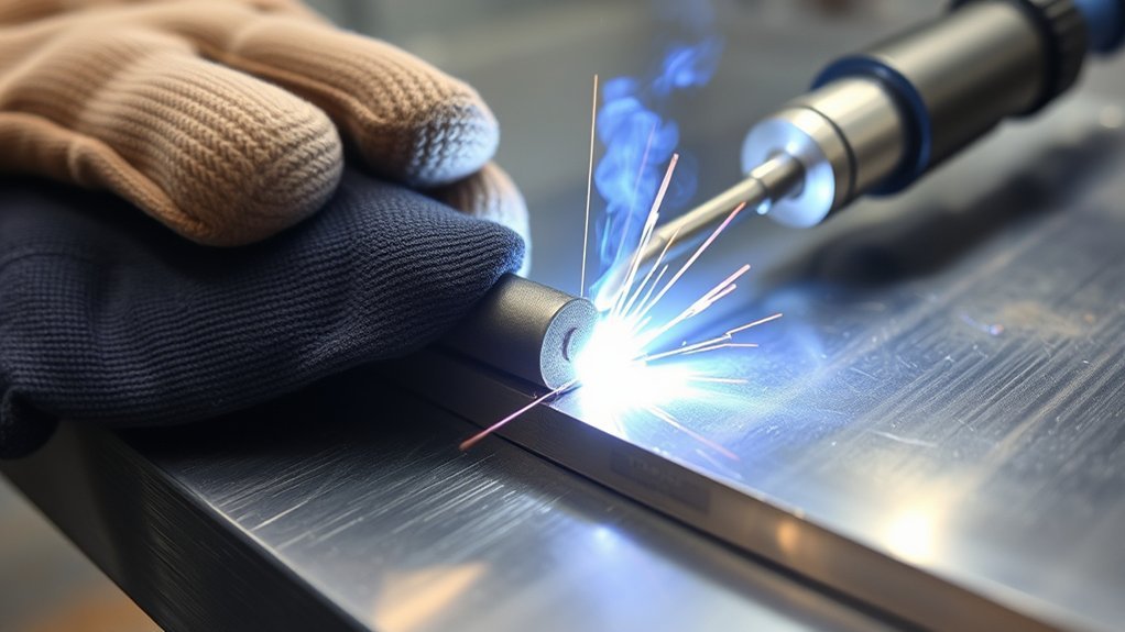
A TIG weld that will not fuse usually means the arc is not melting the joint edges before filler metal is added. Low current, a long or poorly aimed arc, incorrect torch angle, unsuitable joint preparation, contamination, or the wrong travel speed can all leave a bead sitting on the surface. The steps below help you isolate the cause and correct it safely.
Quick Answer
Your TIG weld may not be fusing because the base metal is dirty, the current is too low, the arc is too long, the torch is aimed away from the joint, or filler is being added before a base-metal puddle forms. Clean and refit the joint, verify polarity and tungsten condition, establish a puddle on both edges, and then add filler at the puddle’s leading edge.
Key Takeaways
- Make the base metal melt into a shared puddle before adding filler rod.
- Use AC for most aluminum TIG work and DCEN for most mild-steel and stainless-steel TIG work, unless the approved procedure says otherwise.
- Keep the arc short and aim it at the joint root or leading edge rather than at the filler rod.
- Match current, tungsten size, travel speed, filler diameter, and joint preparation to the actual material and joint.
- A smooth-looking bead does not prove internal fusion; critical welds may need an approved test or professional inspection.
At a Glance
| Time Required | About 10–30 minutes to inspect the setup and make a controlled test weld |
| Difficulty | Beginner to intermediate; critical weld repair requires qualified guidance |
| Tools Needed | TIG welder, correct tungsten and filler, argon supply, clamps, dedicated cleaning tools, scrap test coupon, and welding PPE |
| Cost | Usually no added cost when the correct consumables and cleaning supplies are already available |
Understanding the Importance of Fusion in TIG Welding
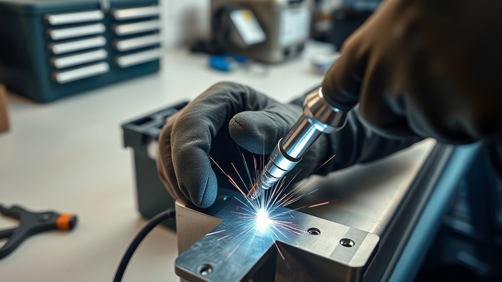
Fusion occurs when the TIG arc melts the base metal and joins it with the weld metal. The puddle must connect to both joint edges and, when full penetration is required, reach the intended root depth. Filler rod should enter an established base-metal puddle instead of being melted by the arc and dropped onto a cold joint.
Lack of fusion is not the same as every other weld problem. Incomplete penetration means the weld did not reach the required joint root. Overlap or cold lap describes weld metal that rolls onto the base metal without fusing at the toe. Porosity consists of gas pockets and usually points to contamination or shielding problems. More than one defect can occur in the same weld.
You control fusion through current, polarity, arc length, torch angle, travel speed, joint design, fit-up, and cleanliness. Oil, oxide, rust, paint, plating, and mill scale can prevent the puddle from wetting into the joint. Filler selection matters too: the alloy must suit the base metal and service conditions, while the filler diameter must be small enough that each addition does not chill the puddle. Use an appropriate TIG filler rod selection chart as a starting point and confirm critical applications against the approved procedure.
A TIG bead can look smooth from the top and still contain incomplete root or sidewall fusion. Appearance alone does not prove that a critical weld is sound.
Symptoms of Lack of Fusion in a TIG Weld
Lack of fusion can be difficult to confirm from the surface, but several clues justify stopping and checking the setup:
- The bead sits high and rounded instead of blending smoothly into the base metal.
- A sharp line remains along one or both weld toes.
- One joint edge melts while the opposite edge stays straight and cold-looking.
- Filler balls up, piles onto the surface, or follows the torch without flowing into the joint.
- The puddle forms on each piece separately but does not bridge the joint.
- A controlled practice coupon separates along the weld interface during an appropriate bend or break test.
Do not keep adding filler to hide these signs. Extra filler can cover the surface while leaving the original unfused interface underneath.
Lack of Fusion vs. Incomplete Penetration
Lack of fusion can occur at the weld toe, sidewall, between passes, or at the root. Incomplete penetration is limited to a joint that did not fuse through the required root depth. A butt joint can have good-looking toes but inadequate root penetration, while a fillet weld can have the expected leg size and still lack fusion along one sidewall.
For a practice coupon, a properly selected bend test or a polished and etched cross-section can reveal fusion more reliably than appearance alone. Do not perform improvised destructive testing on an in-service part.
What Visual Inspection Can and Cannot Confirm
Visual inspection can identify undercut, overlap, cracks, excessive reinforcement, poor tie-in, and inconsistent bead shape. It cannot reliably prove that the root and internal sidewalls fused. Structural, pressure, lifting, vehicle, or other safety-critical welds may require an approved welding procedure and qualified inspection.
Common Causes of Poor Fusion in TIG Welds
Poor fusion usually comes from one or more of the following conditions:
- Insufficient useful heat: The current is too low, the machine cannot supply enough output, or the foot control is not reaching the selected maximum.
- Excessive arc length: A long arc spreads energy, raises arc voltage, and makes the puddle wider and less focused.
- Incorrect arc placement: The arc is aimed at the filler, the center of a large puddle, or only one member instead of the joint root and leading edge.
- Wrong travel speed: Moving too fast prevents the edges from melting. Moving too slowly can create a large filler puddle that the arc rides over without reaching the base-metal edges.
- Contamination: Oxide, oil, coating, moisture, tungsten contamination, or dirty filler interferes with the arc and puddle.
- Poor fit-up or joint design: Uneven alignment, an unsuitable root opening, a thick unprepared edge, or a large heat sink can prevent the arc from reaching the required area.
- Wrong polarity or AC setup: DCEN is normally used for mild and stainless steel, while AC is normally used for aluminum because it combines heating with oxide-cleaning action.
- Incorrect torch angle: Excessive travel angle sends the arc ahead of the joint and reduces direct heat at the root.
- Oversized or poorly added filler: Large, frequent additions can chill a small puddle and cover the joint before the base metal melts.
Manufacturer guidance for basic TIG setup recommends confirming polarity, shielding gas, tungsten size, and equipment condition before changing technique. Proper TIG welding settings are starting points rather than substitutes for watching the puddle.
How to Ensure Proper Joint Fit-Up Before Welding
Check the joint before striking an arc. The edges should be aligned, supported, and prepared so the arc can reach the required fusion area. A root opening that is suitable for thin sheet may be wrong for thick plate, pipe, a fillet, or a joint backed by a heat sink.
Do not apply one universal maximum gap. Use the drawing, welding procedure specification, manufacturer recommendation, or a tested practice coupon to set the bevel, root face, and root opening. Keep the opening consistent from one end of the joint to the other.
Clean the surfaces with tools intended for that material. For aluminum, use a clean stainless-steel brush reserved only for aluminum. Proper metal preparation gives the arc direct access to the base metal.
Products Worth Considering

NO SOLDER POWDER NEEDED: These aluminum rods are flux cored welding rods, no need solder powder, no other materials are required, and it is easy to use.

Fit-Up Pro Medium Radius Marker is constructed of aluminum and tensioned
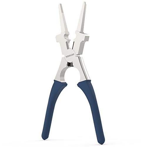
MULTI-FUNCTIONALITY: The welding pliers are meticulously designed for welders who demand precision and efficiency. Perfect for Wire Cutting, Gripping, Tip Removal & Installation, Nozzle Removal & Installation, Inside & Outside Spatter Cleaning, Grooved Tips for Drawing Wire, Hammering and more, this essential tool has you covered.
Joint Preparation Techniques
- Identify the material: Confirm the base alloy, thickness, coating, and filler requirements before grinding or cleaning.
- Remove coatings and scale: Clear paint, rust, oxide, plating, oil, and mill scale far enough from the joint to prevent them entering the puddle.
- Prepare thick edges: Bevel or groove the joint when required so the arc can reach the root without depositing an oversized surface bead.
- Set the root opening: Make it uniform and appropriate for the joint design rather than relying on a general gap rule.
- Tack and clamp: Use enough tacks and support to prevent the opening or alignment from changing as the part heats.
Importance of Alignment
Misalignment changes the distance between the tungsten and each joint edge. The higher edge may absorb most of the arc while the lower edge remains cold. Hold butt joints flush when the design requires it, and keep the torch work angle centered between both members.
On a fillet or T-joint, direct slightly more heat toward the thicker or larger member while still washing the puddle into the thinner side. Make a test coupon first when the two pieces differ greatly in thickness.
Joint Design and Heat Sinks
Heavy fixtures, backing bars, large castings, and thick adjoining parts pull heat away from the weld. If the puddle forms slowly even with correct setup, confirm that the welder has enough output and that the joint preparation suits the available current. Do not compensate by holding a long arc; that spreads the heat and reduces control.
Why Keeping Your Workspace Clean Matters for Good Fusion
A clean workspace reduces the chance that grease, grinding dust, paint flakes, or particles from another alloy reach the joint. Keep filler rods covered, store tungsten electrodes in a clean container, and wipe the bench before fitting the work.
Remove common contaminants such as rust, oil, and loose scale with a method that is compatible with the alloy. Avoid touching a cleaned joint or filler rod with bare, oily hands.
Warning: Never use chlorinated brake cleaner, chlorinated degreaser, or another chlorinated solvent in a welding area. Welding heat and ultraviolet radiation can decompose chlorinated hydrocarbons and produce highly toxic gases, including phosgene. Use only a compatible non-chlorinated cleaner, provide ventilation, and allow the part to dry completely before striking an arc. Wear suitable eye, face, hand, and body protection, remove nearby combustibles, and never TIG weld in an enclosed space where argon could displace oxygen.
Importance of Clean Materials
- Remove heavy contamination mechanically with a dedicated abrasive or brush.
- Wipe the joint with a compatible non-chlorinated cleaner and a lint-free cloth when permitted by the material and shop procedure.
- Allow all cleaner to evaporate and move used rags away from the hot-work area.
- Clean the filler rod if it has oil, dust, oxide, or handling residue.
- Inspect the tungsten and regrind it if it touched the puddle or filler.
Clean material improves arc stability and makes the edge of the puddle easier to see. It does not replace enough current or correct arc placement, but it removes a major source of uncertainty.
Effective Joint Preparation
Prepare and clean the pieces before final assembly when possible. That prevents debris from becoming trapped inside a tight joint. After grinding or brushing, remove loose particles rather than blowing them toward the weld area with compressed air.
For aluminum, clean surface oil first and then remove the oxide with a stainless-steel brush reserved for aluminum. Hobart’s aluminum TIG filler guidance also stresses cleaning contamination before brushing away oxide.
Contamination Prevention Strategies
- Use dedicated tools: Keep separate brushes, abrasive wheels, and files for aluminum, stainless steel, and carbon steel.
- Protect consumables: Store filler and tungsten away from grinding dust, moisture, and oil.
- Regrind contaminated tungsten: Grind lengthwise on a dedicated wheel and follow the tungsten manufacturer’s preparation guidance.
- Check the gas system: Inspect the cup, collet body, O-rings, hose, torch cap, and fittings for damage or leaks.
- Control drafts: Stop fans or outdoor airflow from stripping shielding gas away from the puddle without blocking required fume extraction.
Step-by-Step TIG Fusion Diagnostic Test
Change one variable at a time so you can identify the actual cause. Use clean scrap from the same alloy and thickness as the workpiece whenever possible.
- Confirm the suspected defect: Look for an unfused toe, a bead sitting on the surface, one cold joint edge, or filler that never joins a base-metal puddle.
- Stop welding the finished part: Do not cover the suspected defect with another cosmetic pass.
- Prepare a test coupon: Clean and fit two pieces using the same joint type as the problem weld.
- Check the electrical path: Attach the work lead to clean bare metal, inspect the cable and connector, and verify that the remote control reaches the selected amperage.
- Confirm polarity and mode: Use DCEN for most mild-steel and stainless TIG work and AC for most aluminum TIG work, unless the procedure requires something different.
- Inspect the tungsten: Confirm the type and diameter can carry the intended current. Regrind or replace a split, dirty, rounded, or contaminated electrode.
- Verify shielding gas: Confirm the cylinder contains the correct gas, the valves are open, the flow is reasonable for the cup, and no leak or draft is disturbing coverage.
- Make a fusion-only puddle: Without filler, establish a small puddle that clearly melts both joint edges. If it will not form, correct current, arc length, angle, preparation, or machine capacity first.
- Add filler at the leading edge: Dip only after the base-metal puddle forms. Keep the rod tip within the shielding envelope and out of the direct arc.
- Evaluate the coupon: Check toe blending, root condition, distortion, and consistency. Use an appropriate approved test if the weld’s internal quality matters.
Best Welding Settings for Fusion Success
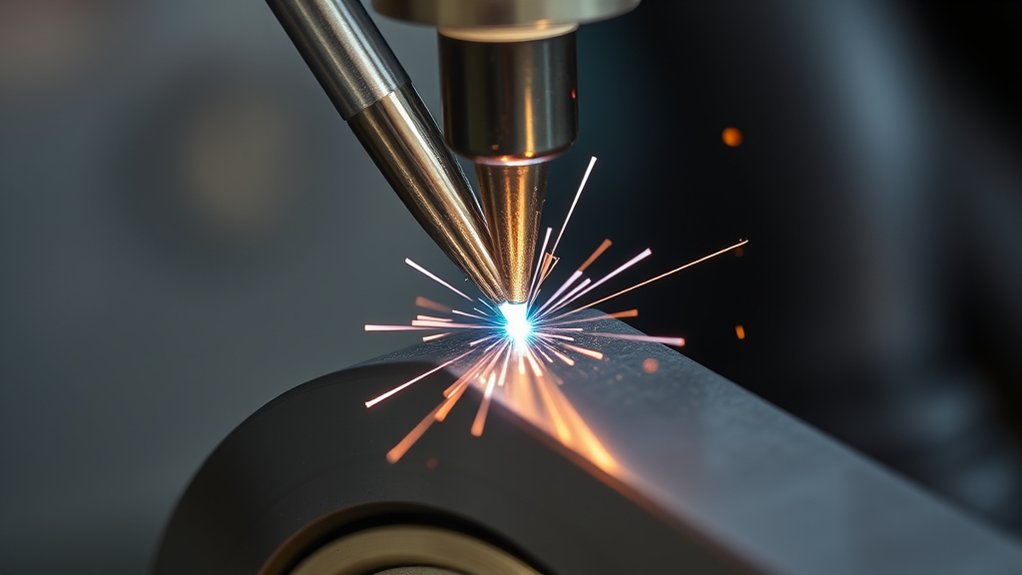
No single group of settings works for every TIG joint. Start with the welder manufacturer’s chart, the approved procedure, or settings proven on a matching coupon.
- Polarity: Use DCEN for most mild-steel and stainless-steel work. Use AC for most aluminum TIG work. Follow the equipment manual for other alloys.
- Current: Select enough maximum current to establish the puddle promptly, then control actual heat with the foot pedal, fingertip control, travel speed, and arc length.
- Shielding gas: TIG commonly uses 100% argon. An argon-helium blend may be selected for some thicker or high-heat applications when the procedure and equipment support it.
- Gas flow: About 15–20 CFH is a common starting range, but cup size, gas lens, torch geometry, drafts, and the machine manual can require a different setting. Excess flow can cause turbulence.
- Tungsten: Match its alloy, diameter, and preparation to AC or DC and the selected amperage. Miller’s tungsten selection guidance lists current ranges and recommends clean gloves to prevent contamination.
- AC balance: Use enough cleaning action to break up aluminum oxide without applying unnecessary electrode-positive time. Control names and scales vary by machine, so follow its manual.
- Pulse: Pulse can help control heat and puddle timing, but very low peak time, background current, or average current can leave the joint too cold. Turn pulse off while diagnosing unless the procedure requires it.
For aluminum, correct cleaning and AC settings help remove the oxide barrier. Review these aluminum TIG welding tips alongside the instructions for your specific machine.
Note: Shielding gas protects the molten metal but does not create fusion by itself. If the puddle is clean yet will not melt both edges, concentrate on current, arc length, torch angle, joint preparation, and travel speed.
Products Worth Considering
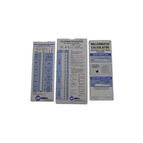
Comprehensive 3‑in‑1 reference pack covers MIG, TIG and Stick welding parameters—ideal for welders who work across multiple processes

Richard Finch, Welder's Handbook: A Complete Guide to MIG, TIG, Arc & Oxyacetylene Welding, "Completely Revised and Updated Edition!" paperback
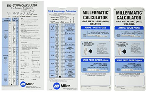
Miller electric 043125 Package, Miller Calculator pack
How to Control Amperage for Improved Fusion
Amperage determines how quickly the arc can melt the joint. Too little current forces you to wait while heat spreads through the part. Too much can cause undercut, burn-through, excessive penetration, or distortion.
A thickness-based amperage shortcut may help an experienced welder estimate a starting point, but it should not replace the machine chart or welding procedure. Joint type, position, alloy, tungsten size, fit-up, backing, and heat sinking can change the required current substantially.
- Set enough maximum current: Give the pedal or hand control enough available output to start the puddle without holding a long arc.
- Establish both edges: Do not add filler until each joint edge visibly melts into a shared puddle.
- Increase current in controlled steps: If the clean coupon remains cold, raise the maximum setting gradually and repeat the same technique.
- Back off as the part heats: Long joints accumulate heat, so less pedal may be needed later in the weld.
- Check machine capacity: If full output still cannot establish the puddle, the joint may require different preparation, a larger machine, or an approved preheat procedure.
Use TIG amperage charts as starting references, not fixed rules.
Mastering Travel Speed for Optimal Fusion
Travel speed controls how long the arc acts on each part of the joint. Moving too fast leaves narrow, cold edges and incomplete root melting. Moving too slowly can overheat the work, but it can also create a large filler puddle that shields the base metal while the arc rides on top of it.
Watch the leading edge of the puddle. The arc should continue melting fresh base metal ahead of the filler deposit. Move only after both joint edges are fluid and connected.
- If the bead is narrow, tall, and poorly blended, slow slightly or increase useful current.
- If the puddle becomes very wide and the toes stop melting, reduce filler additions, correct the arc position, and move before the arc begins riding on deposited metal.
- If the part warps or the edges collapse, reduce average heat, increase control, or use a better sequence and fixture.
- If one side stays cold, correct the work angle instead of simply slowing down.
The best speed depends on thickness, amperage, joint type, position, and the difference between the two workpieces. This is especially important when you TIG weld different thickness metals.
Pro Tip: Practice a short fusion-only pass without filler. When you can hold a small puddle that consistently joins both edges, repeat the pass and add small filler dips at the leading edge. This separates heat and torch-control problems from filler-timing problems.
Troubleshooting Arc Length Issues in TIG Welding
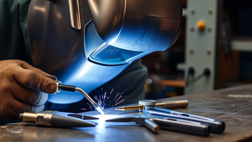
Arc length is the distance from the tungsten tip to the work. A long arc spreads the heat, makes the arc more likely to wander, reduces shielding effectiveness, and makes it harder to aim energy into the joint root.
Where access permits, keep the distance roughly 1/16 to 1/8 inch (about 1–3 mm), then maintain it as the joint profile changes. Do not touch the tungsten to the puddle. If contact occurs, stop and regrind or replace the contaminated electrode.
- Shorten the arc: Bring the tungsten closer while keeping a stable gap.
- Reduce excessive torch tilt: Too much travel angle lengthens the effective arc and pushes heat ahead of the joint.
- Support the torch hand: Use a finger, prop, or sliding support when it is safe and practical.
- Reposition as the joint changes: Maintain the same tungsten-to-work distance around corners and across uneven fit-up.
- Check shielding: Use correct TIG gas flow and keep the cup close enough to protect the puddle.
Torch Angle and Filler Placement
The torch must aim heat into the area that needs to fuse. On a butt joint, center the work angle between the two pieces. On a fillet, aim into the root and adjust slightly toward the thicker member when necessary. Keep the travel angle modest so the arc remains on the leading edge instead of pointing far ahead.
Miller’s TIG technique guidance recommends adding filler at the leading edge of the moving puddle while keeping the rod tip within the shielding-gas envelope.
- Form a shiny base-metal puddle first.
- Move the arc to keep both edges molten.
- Dip the filler into the front edge of the puddle, not into the arc.
- Withdraw the filler only far enough to avoid overheating it while keeping its tip shielded.
- Advance the torch after the deposit wets into both sides.
If the filler balls up before reaching the puddle, shorten the arc, flatten an excessive torch angle, lower the filler angle, and verify that the base metal is already molten.
Material-Specific Fusion Checks
Mild Steel
Use DCEN, clean the joint to bright metal where required, and remove mill scale that blocks wetting. Confirm the work lead has a clean connection. If the bead sits high, establish a larger base-metal puddle before adding filler and check that the tungsten is sharpened and sized for the current.
Stainless Steel
Use DCEN and dedicated stainless tools. Excessive heat can cause a wide bead, heavy discoloration, distortion, and reduced corrosion performance, but running too cold can leave poor toe or root fusion. Use the required purge for joints where the back side must be protected, and follow the approved filler and heat-input procedure.
Aluminum
Use AC on most conventional TIG equipment, remove oil before brushing away oxide, and verify that AC balance provides enough cleaning action. Aluminum transfers heat rapidly, so the joint may need more available current at the start than its appearance suggests. Establish the puddle promptly, then reduce pedal as the part warms.
If the filler remains round and sits on the surface, check for oxide, insufficient current, an overly long arc, or filler being melted by the arc instead of dipped into the puddle.
Quick Troubleshooting Checklist for TIG Fusion Problems
Use this order so you do not change several variables at once:
- Stop and identify the symptom: Determine whether the issue is toe fusion, root penetration, overlap, contamination, or unstable arc behavior.
- Clean the base metal and filler: Remove oil, oxide, rust, paint, mill scale, and moisture with material-compatible methods.
- Inspect fit-up: Correct alignment, joint access, bevel, root opening, and clamping.
- Check the work connection: Clamp to clean bare metal and inspect the cable and connector.
- Confirm polarity: Use AC for most aluminum and DCEN for most mild-steel and stainless TIG work.
- Inspect the tungsten: Verify its type, diameter, point, and cleanliness.
- Check gas coverage: Confirm the gas type, flow, cup condition, hose integrity, and absence of disruptive drafts.
- Turn off unnecessary pulse settings: Simplify the test unless pulse is required by the procedure.
- Establish a base-metal puddle: Make both joint edges melt before adding filler.
- Shorten and aim the arc: Keep it on the joint root and leading edge.
- Correct travel speed: Move steadily without outrunning the puddle or riding on a large filler deposit.
- Adjust current gradually: Repeat the same test technique after each controlled change.
How to Inspect and Repair Lack of Fusion
Do not assume that another pass will repair an unfused interface. New weld metal can cover the defect without remelting it.
- Stop and mark the affected area.
- Determine whether repair is permitted: Structural, pressure, vehicle, lifting, or code-controlled work may require an approved repair procedure.
- Remove the defective metal: Grind, machine, or gouge as permitted until sound base and weld metal are exposed.
- Clean and inspect the excavation: Remove residue and confirm that cracks or unfused boundaries do not remain.
- Correct the original cause: Change preparation, settings, access, consumables, or technique before rewelding.
- Reweld and reinspect: Apply the required visual, destructive, or nondestructive examination.
Do not grind into thin material, pressure boundaries, or load-bearing parts without knowing the remaining thickness and repair requirements.
When to Get Professional Help With TIG Welding Issues
Get professional help when repeated controlled tests do not improve fusion or when the problem suggests a faulty power source, remote control, gas system, torch, cable, or work connection.
A qualified welding instructor, experienced welder, welding engineer, or certified inspector should review structural parts, pressure-containing parts, lifting equipment, suspension or steering components, roll cages, and other safety-critical work. These applications may require a qualified welding procedure and inspection that cannot be replaced by bead appearance.
High-frequency TIG may improve non-contact starting or AC arc stability, but it does not repair poor fusion after the arc is established. Miller’s TIG process guide can help identify the correct starting mode and basic equipment setup.
Frequently Asked Questions
Why is my TIG weld not sticking?
The base metal may be dirty, the joint may be too cold, the arc may be aimed incorrectly, or filler may be added before a base-metal puddle forms. Clean and refit the joint, confirm polarity and tungsten condition, establish a puddle on both joint edges, and then dip filler into the leading edge.
What is the root cause of lack of fusion?
The immediate cause is failure to melt the required base-metal or previous-weld surface. Low useful heat, excessive travel speed, a long or misplaced arc, contamination, poor torch angle, unsuitable joint preparation, and adding too much filler can all create that condition.
How can I tell if a TIG weld is too hot?
Signs include a very wide puddle, undercut, collapsing edges, burn-through, heavy distortion, or loss of puddle control. Stainless steel may show excessive heat tint, while thin aluminum can suddenly sag or melt away. Reduce average heat while maintaining enough current and arc focus to fuse the joint.
Can feeding TIG filler too quickly cause lack of fusion?
Yes. Manual TIG has no powered wire-feed setting, but adding large or frequent filler dips can chill the puddle and cover the joint edges before they melt. Reduce the filler amount and establish a shared base-metal puddle before each addition.
Can too much shielding gas cause poor fusion?
Excessive flow can create turbulence that draws air into the shielding envelope, leading to contamination or an unstable arc. It is usually an indirect contributor rather than the main cause of lack of fusion. Set the flow for the cup, gas lens, torch, and surrounding airflow.
Is lack of fusion the same as lack of penetration?
No. Lack of fusion can occur at a weld toe, sidewall, root, or between passes. Incomplete penetration specifically means the weld did not reach the required depth at the joint root. A weld may have either defect or both.
Can I fix lack of fusion by welding another pass over it?
Not reliably. A cover pass may hide the defect without remelting the unfused interface. The affected weld normally must be removed to sound metal, the original cause corrected, and the joint rewelded under an appropriate repair procedure.
Why does aluminum TIG filler ball up instead of flowing into the joint?
The base metal may not have formed a puddle, oxide may still cover the joint, the arc may be too long, or the filler may be entering the direct arc instead of the puddle. Clean the aluminum correctly, verify AC setup, shorten the arc, and dip the filler into the leading edge of an established puddle.
Conclusion
Strong TIG fusion starts by melting the base metal, not by piling filler onto the joint. Clean and prepare the material, confirm polarity, tungsten, gas, and the work connection, then hold a short arc aimed at the joint root. Establish a shared puddle on both edges before adding small filler dips.
Test changes on matching scrap and adjust one variable at a time. If an existing weld may contain lack of fusion, do not hide it with another pass. Remove and repair the defect using an appropriate procedure, and use qualified inspection whenever the component carries a safety-related load.
Sources
- Miller — Guide to TIG Welding Basics — polarity, shielding gas, tungsten, and basic equipment setup
- Miller — Common TIG Welding Problems — gas flow, contamination, aluminum polarity, and puddle troubleshooting
- Miller TIG Owner’s Manual — tungsten current ranges, AC/DC polarity, and typical argon flow
- OSHA — Welding, Cutting, and Brazing Hazards and Solutions — ultraviolet, electrical, fume, burn, and fire hazards
- CDC — Phosgene Medical Management Guidelines — phosgene formation from chlorinated hydrocarbons near welding
- ESAB — TIG Welding Process Guide — arc length, travel speed, torch angle, and lack-of-fusion troubleshooting




