
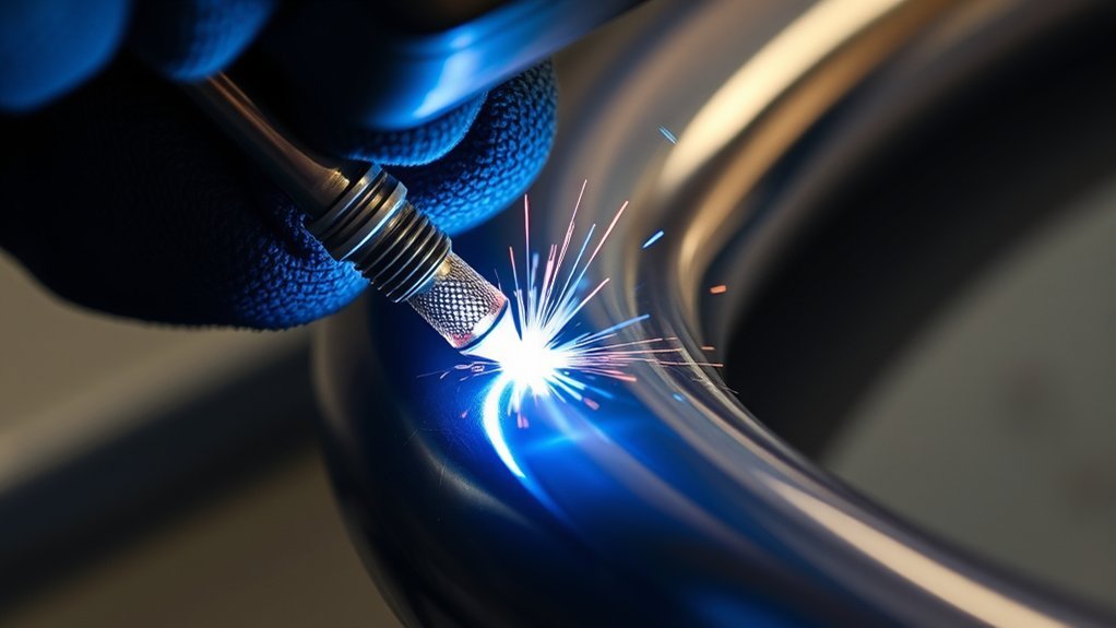
TIG welding 4130 chrome-moly steel tubing takes more than choosing an amperage and making a neat-looking bead. You need to confirm the material condition, clean and fit the joint precisely, select filler metal for the actual design, control heat input, vent enclosed tubing, and inspect the finished joint against the applicable requirements. The procedure matters even more on aircraft, roll cages, suspension parts, bicycle frames, and other structures where a failed weld could cause serious injury.
Quick Answer
To TIG weld normalized 4130 tubing, remove oil and scale, create a close and even fit, vent any hollow section, and use DC electrode negative with straight argon. ER80S-D2 is a common filler for 4130-to-4130 joints, but the drawing or welding procedure controls. Use a short arc, limit heat input, allow controlled cooling, and inspect the joint fully.
Key Takeaways
- Confirm that the tubing is 4130 and identify whether it is normalized, annealed, heat treated, plated, or previously repaired.
- Use a close, even tube fit. Large gaps require more filler and heat, which increases distortion and metallurgical risk.
- ER80S-D2 is a common choice for as-welded 4130-to-4130 fabrication, while other joints may require ER70S-2 or a procedure-specific filler.
- Treat published amperage, gap, gas-flow, and temperature values as starting points unless they come from the approved procedure for your part.
- Vent hollow sections, avoid chlorinated cleaners, and never judge a safety-critical weld by appearance alone.
At a Glance
| Time Required | About 45 to 90 minutes for setup, a practice coupon, fit-up, welding, cooling, and inspection of one simple joint. Complex assemblies take much longer. |
| Difficulty | Advanced. Thin-wall tube fit-up, torch movement, filler control, and heat management require prior TIG practice. |
| Tools Needed | DC TIG welder, argon, suitable tungsten and filler, gas lens or collet body, tube notcher and files, dedicated abrasives, non-chlorinated cleaner, fixture, PPE, ventilation, and inspection tools. |
| Cost | Consumable cost is relatively low if you already have the welder, shielding gas, ventilation, fixtures, and PPE. Professional procedure qualification, heat treatment, or NDT can add substantial cost. |
What’s in This Article
- Understand 4130 Chrome-Moly Steel
- Before You Begin TIG Welding 4130
- Essential Pre-Weld Preparation
- Choose the Right Filler Metal
- Set Up the TIG Welder
- TIG Weld 4130 Tubing Step by Step
- Why Joint Preparation Matters
- Preheat, Cooling, and Heat Treatment
- Inspect the Finished Weld
- Troubleshoot Common Problems
- Best Practices for Consistent Quality
- Frequently Asked Questions
Warning: Do not fabricate or repair an aircraft structure, roll cage, suspension part, pressure-containing assembly, or other safety-critical component from this article alone. Use the approved drawing, welding procedure specification, manufacturer data, governing code, sanctioning rules, and required inspection plan. A smooth bead is not proof that the joint is structurally acceptable.
Understand 4130 Chrome-Moly Steel
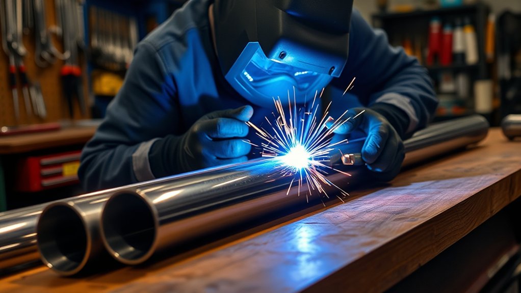
4130 is a low-alloy steel that contains chromium and molybdenum. These alloying elements help the steel provide a useful combination of strength, toughness, and relatively low weight. Builders commonly use 4130 tubing in aircraft structures, race-car chassis, roll cages, suspension components, motorcycle frames, and bicycle frames.
Compared with mild steel, 4130 may provide the required strength with thinner material. That does not mean every 4130 part is automatically stronger. Tube diameter, wall thickness, material condition, weld geometry, heat input, surface condition, corrosion, and service loading all affect the completed structure.
Identify the material condition before welding. Normalized tubing does not behave the same way as a quenched-and-tempered part, a heat-treated fitting, or an unknown component removed from service. If you cannot confirm the alloy and condition from reliable documentation, stop and obtain engineering or metallurgical guidance.
The drawing or qualified procedure must also establish the required joint and weld size. A general guide to maximum fillet weld size cannot replace the requirements for a loaded tube joint.
Precise fit-up and controlled heat input usually protect a 4130 joint more effectively than simply choosing the strongest available filler rod.
Before You Begin TIG Welding 4130
Start by reviewing the drawing, service requirements, and any welding procedure specification. Confirm the tube grade, material condition, wall thickness, joint type, filler classification, preheat requirement, interpass limit, post-weld treatment, and inspection method.
Stop Before Welding If Any of These Apply
- The alloy or material condition is unknown.
- The tube is cracked, badly corroded, deeply gouged, or distorted.
- The part has chrome, cadmium, zinc, paint, powder coating, or another unidentified surface treatment near the weld.
- The part was previously heat treated and no approved repair procedure is available.
- The drawing, code, sanctioning body, or manufacturer prohibits the proposed process or filler.
- You cannot provide a vent path for an enclosed cavity.
- You do not have the required inspection or heat-treatment capability.
Tools and Materials
- TIG welder capable of stable direct current electrode negative output
- Documented 4130 tubing in the required material condition
- Procedure-approved filler, commonly ER80S-D2 for many 4130-to-4130 applications
- Properly sized 2% ceriated or 2% lanthanated tungsten
- Straight argon shielding gas
- Gas lens or suitable collet body and cup
- Tube notcher, saw, files, deburring tools, and dedicated abrasives
- Non-chlorinated degreasing solvent such as acetone, used according to its safety data sheet
- Clean brush used only on compatible ferrous material
- Fixture, jig, clamps, and alignment tools
- Temperature-measuring equipment when the procedure specifies preheat or interpass control
- Welding helmet, safety glasses, TIG gloves, protective clothing, ventilation, and fire protection
Some welders still use thoriated tungsten for DC TIG. It can perform well, but grinding creates thorium-containing dust. Many shops choose ceriated or lanthanated tungsten to avoid that additional exposure and disposal concern. Follow your employer’s procedure, the electrode safety data sheet, and local requirements.
Basic electrode selection principles still apply, but match the tungsten diameter and preparation to your machine, current range, and torch setup.
Warning: Never clean a weld joint with a chlorinated brake cleaner or another chlorinated solvent. Welding-arc heat and ultraviolet radiation can break down residues into highly toxic compounds. Use an approved non-chlorinated cleaner, remove the container from the hot-work area, and let the tube dry completely before striking an arc.
Essential Pre-Weld Preparation
Preparation controls how much heat and filler you need to complete the joint. Clean metal, an accurate cope, stable fixturing, and a vented assembly make the puddle easier to control and reduce the chance of porosity, burn-through, distortion, and incomplete fusion.
Clean the Material
Remove protective oil, paint, rust, mill scale, cutting fluid, marker residue, adhesive, and grinding debris from the tube. Mechanically clean far enough from the joint that coatings and contamination cannot enter the heated area. Finish with a clean, lint-free wipe and non-chlorinated solvent.
Clean the inside edge of the tubing as well as the outside. Burrs, cutting lubricant, and residue inside the tube can release gas when heated. Keep the filler wire, gloves, workbench, and tungsten clean so you do not transfer contamination back to the prepared surface.
Create a Close, Even Fit
Notch or cope the tube so the joint contacts evenly around its circumference. Avoid using the weld bead to bridge a poorly cut joint. Large or irregular gaps increase filler volume, arc time, heat input, shrinkage, and the chance of an uneven root.
Lincoln Electric publishes one example schedule for normalized 0.035-inch-wall 4130 tubing with a 0.000–0.010-inch joint gap. Treat that as a reference for that specific example, not a universal tolerance. The drawing or approved procedure controls your joint gap and weld profile.
Hold the parts in a rigid but practical fixture. Confirm the centerline, angle, and tube orientation before tacking. Make sure the fixture does not hide part of the joint or prevent you from maintaining a short arc.
Vent Hollow Tubing
Provide a vent path before welding a tube or cavity closed. Heated air and gas expand. If the cavity is sealed, pressure can disturb the puddle, cause porosity, blow out the final section of the weld, or eject hot metal.
Place the vent according to the drawing or fabrication plan so it remains open while the final joint is welded. Do not casually seal or relocate a vent on an aircraft, pressure-containing component, corrosion-controlled structure, or part governed by an engineering specification.
Tool Readiness Checklist
- The work lead connects to clean metal and the welding circuit is secure.
- The cylinder is restrained, the regulator is sound, and gas reaches the torch without leaks.
- The tungsten has a clean lengthwise-ground point with no embedded contamination.
- The cup and gas lens are clean and correctly assembled.
- The filler wire is clean, dry, correctly classified, and suitably sized.
- The tube joint is clean inside and outside.
- The assembly has a safe vent path.
- The fit, angle, and tack locations match the drawing.
- A same-material, same-thickness practice coupon is ready.
- Fire hazards have been removed or protected, and ventilation is operating.
Choose the Right Filler Metal for 4130
Filler selection affects deposited weld strength, ductility, cracking behavior, heat-treatment response, and compatibility with the adjoining material. Do not choose a rod only because it is available in the shop.
| Filler | Typical Use | Important Limit |
|---|---|---|
| ER80S-D2 | Common choice for many light- and medium-gauge 4130-to-4130 TIG joints that will remain in the as-welded condition. | It is not automatically correct for every material condition, load, joint, or governing specification. |
| ER70S-2 | Often considered for 4130-to-mild-steel joints and for procedures that intentionally use an undermatched filler. | Its lower strength class does not make it suitable without design or procedure approval. |
| 4130 filler | Procedure-controlled fabrication that will receive suitable post-weld heat treatment. | Do not use it as the default on thin tubing that will remain as-welded because the deposited metal can become excessively hard or lack required ductility. |
| Stainless filler | Only when a qualified design or procedure specifically requires it. | Do not select 309, 312, or another stainless classification merely to obtain a strong-looking or crack-resistant bead. |
Use a filler diameter that lets you add small, controlled amounts without overheating the tube. Current Miller guidance recommends avoiding filler that is thicker than the base material. For example, it suggests 0.045-inch filler rather than 1/16-inch filler on 0.049-inch-wall chromoly when the procedure and product availability allow it.
ER80S-D2 is capable of producing an approximately 80 ksi-class weld deposit under its classification requirements, but the finished joint is not defined by filler strength alone. Dilution, heat input, bead geometry, defects, base-metal condition, and service loading still matter.
General filler rod selection charts can help you compare classifications, but the approved procedure remains the final authority.
Products Worth Considering

er308l stainless steel tig welding rods 1 16 x 16 1 6mm tig filler rod thin stainless sheet tubing handrail kitchen equipment low splatter corrosion resistant stainless steel welding wire tig welding accessories gta w argon arc

Premium Material: Crafted from high-grade stainless steel, ER308L rods ensure superior strength & durability for professional welding work

ER4043 TIG WELDING ROD: This TIG welding rod has 5% added silicon, This can improve the liquidity of the melt pool.
Set Up the TIG Welder
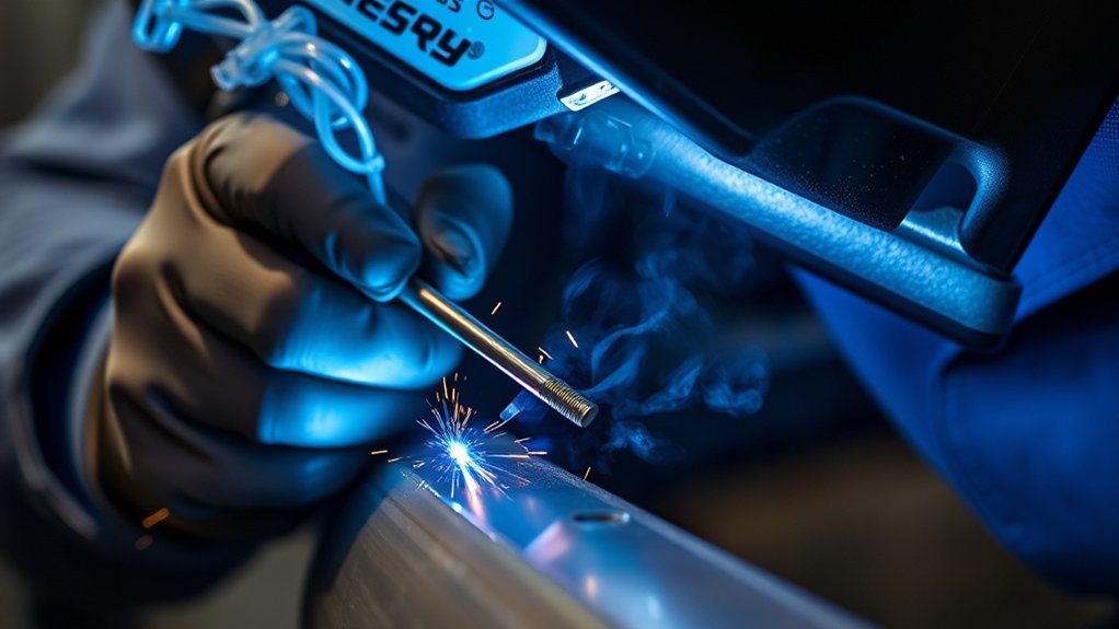
Use direct current electrode negative for normal TIG welding of 4130 steel. Set enough maximum current to establish the puddle promptly, then control the actual heat with the pedal, fingertip control, travel speed, arc length, and filler timing. A low maximum setting can be as troublesome as an excessive one if it forces you to hold the arc on the joint for too long.
| Parameter | Practical Starting Guidance |
|---|---|
| Polarity | DC electrode negative |
| Shielding gas | Straight argon for normal manual TIG welding |
| Gas flow | About 15–20 CFH is a common indoor starting range. Adjust for cup size, gas lens, tungsten extension, leaks, joint access, and drafts. Excess flow can create turbulence. |
| Tungsten | A pointed 1/16-inch ceriated or lanthanated tungsten works for many light-gauge joints. Confirm its current capacity in the electrode and machine documentation. |
| Arc length | Keep it short and stable, commonly about 1/16 to 1/8 inch from the work. Do not touch the puddle. |
| Torch angle | Use a slight push angle that preserves gas coverage and lets you see both toes of the joint. Avoid leaning the torch so far that the arc stretches. |
| Post-flow | Follow the machine manual. A common Miller rule of thumb is about one second for every 10 amps while keeping the torch over the cooling weld end. |
Lincoln Electric publishes an example for normalized 0.035-inch-wall 4130 tubing using ER80S-D2 filler of 0.035-inch diameter, a 0.000–0.010-inch gap, DCEN, and 20–40 amps. That is a useful test-coupon starting point for a similar joint, but it is not a universal setting chart.
Do not transfer parameters from unrelated processes. A guide to TIG settings for stainless steel may explain machine controls, but stainless settings do not automatically apply to 4130. Likewise, matching tip size to amperage is important in plasma cutting but does not establish a TIG welding schedule.
Pro Tip: Prepare at least two scrap joints from the same tubing, filler, and joint geometry. Weld one to establish settings and use the second to confirm that you can repeat the bead without burn-through, excessive reinforcement, missed toes, or an oversized heat-affected zone.
Products Worth Considering

Extra-Long 13-FT Air Hose: Instead of moving the Argon welding cylinder tank all around, ARCCAPTAIN TIG Torch equipped with an extra-long 13-FT air hose and cables brings enormous convenience for distance welding. Meanwhile(furthermore), the cables are made of durable rubber hose with nylon over-braid, super-light, this innovative design makes the TIG welding torch keep(super) flexible under any circumstances.
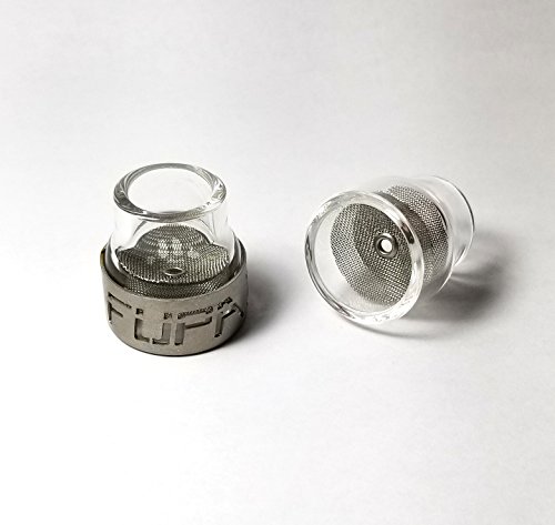
2 full cups, spare gas lens diffuser, o-rings for mounting and one Titanium protector.
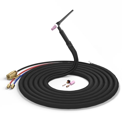
WP-20F: Premium quality 250Amp water-cooled flexible head WP-20 complete TIG welding torch package with 25ft power cable.
How to TIG Weld 4130 Chrome-Moly Tubing Step by Step
- Confirm the requirements. Verify the alloy, material condition, wall thickness, drawing, filler, joint profile, preheat instructions, heat-treatment requirements, and inspection plan.
- Prepare a representative coupon. Use the same tubing thickness, cope, filler, torch setup, and welding position as the final joint.
- Clean the tubing. Remove scale, oil, coatings, burrs, and cutting residue from the inside and outside. Finish with an approved non-chlorinated cleaner and let the tube dry.
- Fit and vent the joint. Create close, even contact around the cope. Provide a vent path for any cavity that could become enclosed during welding.
- Fixture and tack the tubes. Confirm alignment before placing small, evenly distributed tacks. Four tacks may suit a simple round joint, but the number and positions depend on diameter, fit, restraint, and procedure.
- Inspect the tacks. Remove and replace any tack with cracking, porosity, contamination, an oversized lump, or missed fusion. Do not bury a defective tack under the final bead.
- Set the welder. Select DCEN, straight argon, suitable tungsten, correct filler, and a current range tested on the coupon.
- Establish a small puddle. Hold a short arc and direct the heat so both edges begin to fuse. Avoid dwelling on the thinner or more exposed edge.
- Add filler at the leading edge. Keep the filler tip inside the shielding envelope. Add small, repeatable amounts without touching the tungsten.
- Travel around the joint steadily. Reposition before your wrist locks or the torch angle becomes excessive. If you stop, maintain shielding, restart on sound metal, and blend the restart without creating a cold lap or crater crack.
- Control the welding sequence. Use the sequence specified for the assembly. Balanced segments may reduce movement on some structures, while other procedures require a continuous pass.
- Finish and shield the crater. Taper current down, add filler if needed to fill the crater, and keep the torch over the weld until post-flow ends.
- Allow the required cooling cycle. Do not quench the tube or blast it with compressed air. Follow any specified postheat, hold time, insulation, or controlled-cooling instructions.
- Inspect the entire circumference. Check the bead, toes, tacks, starts, stops, root condition where visible, and adjacent tube surface before removing the assembly from the fixture.
Why Joint Preparation Matters
Good joint preparation reduces the amount of weld metal and heat needed to complete the connection. It also helps the weld transfer load through the intended geometry instead of through one narrow, overheated, or poorly fused area.
Cleanliness Improves Fusion and Shielding
Oil, scale, rust, cutting residue, moisture, and dirty filler can release gas into the puddle or prevent the weld from wetting into the tube. Cleaning must cover the full heat-affected area, not just the line where the arc will travel.
Keep abrasives material-specific where practical. Recheck the joint after fixturing because clamps, gloves, marking tools, and a dirty bench can contaminate a surface that was clean minutes earlier.
Alignment Reduces Heat and Distortion
An accurate cope supports consistent puddle size and toe fusion. A changing gap forces you to slow down, add more filler, or vary the arc position. Those corrections can leave excess reinforcement in one area and lack of fusion in another.
Tack the joint in a sequence that keeps the tube aligned. Recheck the angle and centerline after tacking and before completing the weld. Correct movement during fit-up instead of trying to pull the assembly back into place with a large weld.
Preheating methods used for unrelated materials, such as preheating cast iron, should not be copied to 4130. Each alloy and repair procedure has different temperature and cooling requirements.
Preheat, Interpass Control, Cooling, and Heat Treatment
There is no safe universal rule that every 4130 tube over one wall thickness must receive the same preheat or post-weld temperature. The correct treatment depends on the base-metal condition, thickness, restraint, filler, hydrogen control, heat input, joint design, service, and governing procedure.
When Preheat May Be Required
A qualified procedure may require preheat for heavier sections, highly restrained joints, heat-treated components, low ambient temperatures, dissimilar thicknesses, or applications with strict hardness and hydrogen-control limits. Thin normalized tubing is often welded under procedures that do not require a high preheat, but that practice cannot be extended automatically to every 4130 part.
Measure preheat using the method required by the procedure. Heat the specified area uniformly and observe the required interpass range. Do not aim a torch at one small spot until it changes color.
Postheat Is Not the Same as PWHT
- Post-flow is shielding gas that continues after the arc stops.
- Immediate postheat keeps a weld warm for a specified period, often as part of hydrogen control.
- Stress-relief PWHT uses a controlled heating, holding, and cooling cycle to alter residual stress and metallurgical properties.
- Normalizing or full heat treatment uses a higher-temperature cycle intended to change the steel’s microstructure and properties.
Do not apply a generic 1,100°F stress-relief cycle or a higher normalizing cycle without written instructions. A correct temperature without the correct heating rate, soak time, uniformity, support, and cooling rate can still damage or distort the part.
Note: FAA guidance for welded aircraft structures directs fabricators to follow the applicable manufacturer data or accepted procedure and warns that 4130 work may require controlled preheat, interpass heat, postheat, and low-hydrogen practice. Aircraft work also carries approval and documentation requirements beyond making the weld.
Inspect the Finished 4130 Weld
Let the joint reach the inspection condition required by the procedure, then clean only enough residue to see the complete bead and surrounding tube. Do not grind a structural weld smooth unless the design and procedure expressly allow it.
Visual Inspection Checklist
- No visible cracks in the bead, crater, tack locations, toes, or heat-affected area
- No open porosity, pinholes, or contaminated sections
- No missed sections around the circumference
- No obvious lack of fusion, overlap, or cold lap at either toe
- No unacceptable undercut or sharp groove beside the bead
- No burn-through, collapsed tube wall, or excessive root protrusion where the root can be viewed
- No excessive reinforcement or abrupt bead shape that creates an unintended stress concentration
- No stray arc strikes, deep grinding marks, or damage to the adjoining tube
- No movement that places the assembly outside its dimensional tolerance
The drawing, code, WPS, manufacturer, or sanctioning body defines what is acceptable. Visual inspection cannot reveal every internal flaw or confirm the final metallurgy.
Additional Testing for Critical Work
A qualified inspector may require liquid penetrant, magnetic-particle testing, radiography, ultrasonic testing, hardness checks, dimensional inspection, or another method suited to the joint. The selected method must be capable of finding the relevant defect in that geometry.
Before welding the final assembly, a shop may also section, polish, etch, bend, or otherwise destructively test a representative coupon. Coupon testing does not qualify an unapproved structural procedure by itself, but it can expose poor penetration, excessive root profile, lack of fusion, or inconsistent technique before those problems reach the part.
Troubleshoot Common 4130 TIG Welding Problems
| Problem | Likely Causes | Corrective Action |
|---|---|---|
| Porosity | Oil, moisture, scale, dirty filler, gas leak, excess gas turbulence, drafts, or pressure escaping from a closing tube | Remove the defective metal as permitted, reclean inside and outside, leak-test the gas system, correct flow, shield the work from drafts, and verify the vent path. |
| Burn-through | Excess current, long dwell, long arc, oversized gap, large filler, or poor torch access | Improve fit-up, shorten the arc, establish the puddle quickly, travel steadily, reduce actual pedal current, or use a more manageable filler size. |
| Lack of fusion | Insufficient heat at a toe, excessive filler, arc aimed at one tube, contamination, or travel that is too fast | Reclean, direct the arc into both edges, reduce filler volume, and adjust current or travel on a practice coupon. |
| Cracking | Wrong filler, hard weld metal, hydrogen, crater shrinkage, high restraint, excessive heat, rapid cooling, or an unsuitable procedure | Stop welding. Do not cover the crack. Determine and correct the cause, then follow the approved removal and repair procedure. |
| Undercut | Too much local heat, long arc, poor torch angle, fast travel, or inadequate filler at the toe | Shorten the arc, balance heat between both tubes, correct the torch angle, and add filler consistently without building excessive reinforcement. |
| Unstable arc | Contaminated tungsten, wrong polarity, loose work lead, gas problem, or excessive tungsten extension | Stop, regrind or replace the tungsten, confirm DCEN, secure the welding circuit, inspect the torch, and restore correct gas coverage. |
| Excessive distortion | Poor fit, oversized weld, long dwell, unbalanced sequence, weak fixture, or too many repairs | Correct fit-up, reduce unnecessary weld volume, improve fixturing, and use the specified sequence. Do not force a critical assembly back into alignment without engineering approval. |
Check the work lead and all cable connections when the arc behaves unpredictably. The general grounding principles in this proper grounding safety guide also apply to maintaining a complete and secure welding circuit, although the equipment setup differs.
Best Practices for Consistent Weld Quality
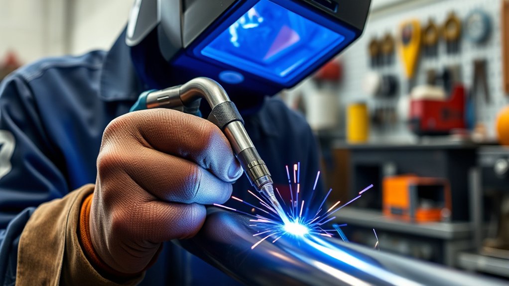
- Record the tube specification, wall thickness, joint type, filler, tungsten, cup, gas flow, maximum current, and successful technique for each approved setup.
- Use the same preparation sequence on every joint.
- Keep the tungsten close enough for a concentrated arc without touching the puddle.
- Use a gas lens when it improves shielding around curved tubing or permits safe access with additional tungsten extension.
- Choose filler small enough for controlled additions.
- Inspect every tack before welding over it.
- Plan body and torch movement before starting the arc.
- Keep starts, stops, and craters shielded while they solidify.
- Do not quench the finished joint.
- Reject or repair defects under an approved procedure rather than hiding them with another pass.
- Protect the finished structure from corrosion according to the design specification.
Settings and consumables used for another alloy should not be copied blindly. For example, using stainless wire is appropriate in specific stainless-steel applications, but stainless filler is not the default choice for a 4130 tube joint.
Note: Keep documentation for safety-critical work. Material certificates, welder qualifications, procedure records, filler batch information, temperature records, inspection reports, and repair history may all be required by the project.
Frequently Asked Questions
Can you weld 4130 chromoly?
Yes. 4130 can be welded successfully when you identify its material condition, use a suitable process and filler, prepare the joint correctly, control heat input, follow any required thermal treatment, and inspect the result. Safety-critical parts require an approved procedure and qualified personnel.
Do you have to TIG weld chrome-moly tubing?
Not in every application. Qualified procedures may use TIG, MIG, oxy-fuel, or another process. TIG is widely preferred for thin 4130 tubing because it gives the welder close control over the arc, heat input, filler addition, starts, and stops. The drawing, code, manufacturer, or sanctioning body may restrict the process.
What is the best TIG filler wire for 4130 chromoly?
ER80S-D2 is a common choice for many light- and medium-gauge 4130-to-4130 joints that remain as welded. ER70S-2 may be specified for chromoly-to-mild-steel or other procedure-controlled joints. Matching 4130 filler is generally reserved for work that will receive suitable post-weld heat treatment. There is no single best filler for every design.
Can you weld chrome-molybdenum steel to mild steel?
Yes, but the joint is a dissimilar-material connection and must be designed accordingly. Current Miller guidance identifies ER70S-2 as a common option for joining chromoly to mild steel. Confirm the filler, weld profile, load path, and inspection requirements with the approved procedure.
Should you stress relieve 4130 after TIG welding?
Only when the design or approved procedure requires it. Thin normalized tubing is often welded under procedures that do not call for full PWHT, while thicker, restrained, heat-treated, or critical parts may require controlled preheat, postheat, stress relief, normalizing, or another cycle. Do not apply a generic temperature with a hand torch.
What causes cracks when welding 4130 tubing?
Possible causes include hydrogen or other contamination, incorrect filler, high restraint, excessive hardness, poor crater filling, excessive heat input, an unsuitable cooling rate, defective tacks, or an unqualified repair. Stop when you find a crack. Do not weld over it without identifying the cause and following an approved removal and repair procedure.
Does 4130 tubing always need preheat?
No. Some qualified procedures for thin normalized tubing do not require a high preheat. Other parts require controlled preheat because of thickness, restraint, base-metal condition, hydrogen control, ambient conditions, or service requirements. Use the specified procedure rather than a universal wall-thickness rule.
Do you need to back purge 4130 tubing?
Not automatically. Backing gas may be required by a particular root-quality, cleanliness, or service specification, but it is not a universal requirement for every 4130 tube joint. The inside surface must still be clean, and every hollow section must have an outlet so purge gas or heated air cannot build pressure.
Safety Disclaimer: This article provides general educational information. It does not replace welding training, a welding procedure specification, engineering review, material certification, manufacturer instructions, code requirements, welder qualification, heat-treatment control, or inspection. Consult qualified professionals before welding any safety-critical component.
Conclusion
Reliable 4130 TIG welds start before the arc is struck. Confirm the material and governing requirements, prepare an accurate and vented joint, select filler for the actual application, test the setup on representative scrap, and keep the arc short enough to control heat. After welding, follow the specified cooling or heat-treatment cycle and inspect the joint against real acceptance criteria. When a part carries people or critical loads, use a qualified procedure and professional inspection rather than relying on bead appearance.
Sources
- Miller Electric: TIG Welding Chromoly Steel, Five Tips to Improve Results — cleaning, gas lenses, shielding, filler size, and filler selection
- Lincoln Electric: TIG Welding Chrome-Moly Tubing — published example procedure for normalized 0.035-inch 4130 tubing
- Miller Electric: Guide to TIG Welding Basics — tungsten, gas flow, arc length, polarity, and post-flow guidance
- Federal Aviation Administration AC 23-27 — material condition, structural welding, heat-control, and aircraft approval considerations
- OSHA: Welding, Cutting, and Brazing Chemical Hazards — fumes and hazardous decomposition products from cleaning residues
- OSHA 29 CFR 1910.252 — ventilation, fire prevention, hot-work safety, and venting hollow spaces



