A MIG contact tip has two jobs: guide the welding wire and transfer current into it before the wire reaches the arc. The correct tip starts with the wire’s nominal diameter, but you also need the right tip family, bore design, material, liner, drive rolls, and contact-tip position for your gun and welding process.
Quick Answer
Start with a MIG contact tip marked for the same nominal diameter as your wire, such as .030, .035, or .045 inch. Use a purpose-made aluminum tip for aluminum wire, and never assume that a different thread, length, or tip series will fit your gun. Check the gun manual before changing from the matched size.
Key Takeaways
- Choose the contact tip marked for your wire diameter unless the gun or consumable manufacturer specifies another option.
- A tip’s size marking identifies the wire it is designed to feed; it does not always equal the tip’s exact measured bore.
- Use aluminum-specific tips, a nonmetallic liner, and aluminum drive rolls when your equipment requires them.
- A loose, damaged, overheated, undersized, oversized, or worn tip can contribute to erratic feeding, burnback, keyhole wear, and arc instability.
- Tip bore size, contact tip recess, wire stickout, and contact-tip-to-work distance are separate setup variables.
What’s in This Article
- MIG Contact Tip Size Chart
- How MIG Contact Tip Sizes Work
- How to Select a MIG Contact Tip
- Choose the Right Tip for Your Wire Type
- Check Contact Tip Compatibility
- How Welding Process Affects Tip Setup
- Why Oversized and Undersized Tips Fail
- How to Spot the Wrong Tip Size
- Choose the Best MIG Contact Tip Material
- Drawn vs. Drilled MIG Contact Tips
- Set Tip Size for Manual and Robotic Welding
- Prevent Burnback, Spatter, and Arc Wander
- What Contact Tip Size Does Not Control
- Frequently Asked Questions
- Conclusion
- Sources
MIG Contact Tip Size Chart
Use the chart below as a starting reference. Select a contact tip that your gun manufacturer lists for the wire’s nominal diameter. Product labels vary, especially around 0.6 mm and 1.2 mm wire, so the gun’s consumable chart takes priority over a generic conversion.
| Nominal wire diameter | Metric category | Tip marking to start with | Important note |
|---|---|---|---|
| .023, .024, or .025 in. | 0.6 mm | The exact .023, .024, .025, or 0.6 mm tip listed for the gun | Manufacturers use different inch labels for 0.6 mm systems. Do not assume every label is interchangeable. |
| .030 in. | 0.8 mm | .030 or 0.8 mm | Common for light sheet metal and general small-machine work when the welder supports it. |
| .035 in. | 0.9 mm | .035 or 0.9 mm | Use the matching liner and drive-roll groove as well as the matching tip. |
| .040 in. | 1.0 mm | .040 or 1.0 mm | Confirm that your gun, drive rolls, and power source support this size. |
| .045 in. or 3/64 in. | 1.2 mm | The .045, 3/64, 1.2 mm, or aluminum-specific tip listed by the manufacturer | .045 and 3/64 inch are not mathematically identical, even though both may appear in 1.2 mm product groups. |
| .052 in. | 1.4 mm | .052 or 1.4 mm | Usually requires a higher-capacity gun and feed system. |
| 1/16 in. | 1.6 mm | 1/16 or 1.6 mm | Common in heavier production work. Check gun amperage and consumable-series limits. |
| 5/64 in. | 2.0 mm | 5/64 or 2.0 mm | Used with equipment designed for large wire and high deposition rates. |
| 3/32 in. | 2.4 mm | 3/32 or 2.4 mm | Not supported by ordinary hobby MIG guns. Use only an approved industrial setup. |
Note: A tip marked .035 is designed for .035-inch wire, but its exact finished bore is normally larger than .035 inch. The amount of clearance depends on the tip design, wire type, material, and manufacturer. Do not measure a used bore and compare it directly with the number stamped on the tip.
How MIG Contact Tip Sizes Work
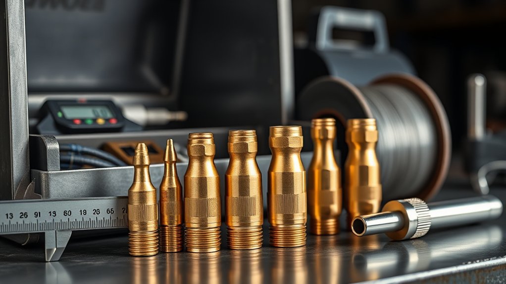
The contact tip connects to the gas diffuser and carries welding current into the continuously fed electrode. The wire must move through the bore with low mechanical resistance while touching the bore often enough for reliable current transfer.
A tip that is marked for the wire size is designed with the necessary clearance already built into that product. For most semiautomatic welding, Bernard and Tregaskiss recommend starting with a contact tip that matches the wire’s marked size.
The contact tip is only one part of the feed system. Your MIG wire, spool or drum, inlet guide, drive rolls, liner, gun cable, diffuser, and tip must work together. Changing only the tip cannot correct a damaged liner, excessive drive-roll pressure, dirty wire, or a tightly coiled gun cable.
Wire packaging also changes how the electrode enters the tip. Wire from a small spool normally has more cast, or curvature, than wire drawn from a large production drum. That difference can affect where the wire contacts the bore and how the tip wears.
How to Select a MIG Contact Tip
- Read the wire label. Confirm the material, AWS classification, nominal diameter, and whether the wire is solid, metal-cored, gas-shielded flux-cored, self-shielded, or aluminum.
- Check the gun manual or consumable chart. Find the approved tip series, thread, length, seat, and wire-size marking.
- Start with the nominally matched tip. For .035-inch steel wire, begin with the compatible .035 or 0.9 mm tip listed for the gun.
- Use a purpose-made aluminum tip for aluminum wire. Do not create extra clearance by randomly substituting an incompatible steel-wire tip.
- Match the rest of the feed path. Confirm the drive-roll groove, liner range, inlet guides, gun rating, and feeder capacity.
- Check contact tip recess. Use the nozzle and diffuser combination specified for the transfer mode and current range.
- Test on scrap. Feed wire with the gun arranged as it will be used, then confirm smooth delivery and a stable arc before welding the finished part.
Warning: Turn off the welding power source before removing or installing a contact tip, liner, drive roll, or wire spool. Keep your eyes and hands away from the gun outlet while inching wire because the wire end can emerge suddenly and puncture skin or injure an eye.
Products Worth Considering

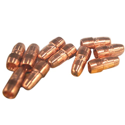
20Pcs Contact Tip .035'' Ø0.9mm
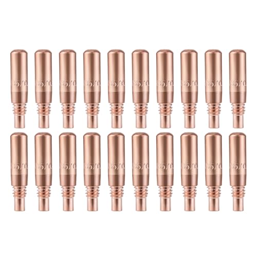
Package Including Pack of 20 Premium Quality Contact Tips .035" (0.9mm).

MIG Contact tips
Choose the Right Tip for Your Wire Type
Wire diameter sets the nominal tip size, while wire material and construction determine which version of that tip you should use. Follow the wire and gun manufacturers instead of applying one clearance rule to every electrode.
| Wire type | Starting tip choice | Other setup checks |
|---|---|---|
| Solid steel or stainless wire | Tip marked for the nominal wire diameter | Correct V-groove rolls, liner range, polarity, shielding gas, and gun rating |
| Metal-cored wire | Manufacturer-listed tip for the wire diameter | Wire surface, cast, high feed speed, current load, and tip material |
| Gas-shielded flux-cored wire | Matched nominal tip unless the consumable chart specifies otherwise | Knurled or recommended drive rolls, liner condition, polarity, and gas |
| Self-shielded flux-cored wire | Matched nominal tip approved for the gun and wire | Correct polarity, drive-roll pressure, wire classification, and outdoor wind conditions |
| Aluminum wire | Purpose-made aluminum contact tip listed for the wire and gun | U-groove rolls, low roll pressure, nonmetallic liner, smooth guides, and spool-gun or push-pull compatibility |
Products Worth Considering
20Pcs Contact Tip .023'' Ø0.6mm

Package list: 30 pieces of 0.030 inch mig welder tips.
Solid Steel Wire
Use the tip marked for the solid wire diameter in ordinary manual welding. A smaller bore may increase contact pressure, but it can also increase drag, feeding variation, and burnback. Do not deliberately undersize a manual setup merely to make the arc feel sharper.
Wire from large production drums can have much less cast than wire from a small spool. Some robotic operations test a tip one nominal size smaller to improve current transfer, but that is a process-development decision, not a general starting rule.
Flux-Cored and Metal-Cored Wire
Start with the nominally matched tip for tubular wire unless the wire, gun, or tip manufacturer specifies a different consumable. Tubular wire can be more abrasive than copper-coated solid wire, so tip material and wear resistance may matter more than adding bore clearance.
The correct choice also depends on the type of flux-cored wire. Self-shielded and gas-shielded electrodes can require different polarity, shielding, drive-roll, and parameter choices. Review your flux-core welding settings before blaming the contact tip for every rough arc.
Aluminum Wire
Aluminum is softer, expands more with heat, and is easier to shave or deform than steel wire. ESAB recommends a smooth aluminum-specific contact tip with a bore about 10–15% larger than the electrode diameter.
The extra clearance should come from a tip designed and labeled for aluminum, not from guessing at the next steel-wire size. You also need smooth inlet guides, U-groove drive rolls, light drive pressure, and a PTFE, nylon, or other approved nonmetallic liner. A spool gun or push-pull system may be necessary when a conventional push feeder cannot deliver the wire consistently.
Pro Tip: When aluminum repeatedly fuses to the tip, inspect the entire feed system before installing another tip. A rough liner, sharp guide, excessive roll pressure, long cable, or tight cable bend can create enough drag to cause another burnback.
Check Contact Tip Compatibility
A .035 tip from one product line may not fit another .035 gun. The wire-size marking describes the electrode category, not the tip’s external geometry.
Confirm all of the following before buying or installing a replacement:
- Tip series: The manufacturer’s consumable family or part-number system.
- Thread: Common systems use different metric or proprietary threads.
- Length and outside diameter: These affect fit, cooling, nozzle clearance, and recess.
- Seat and connection: Tapered, threaded, drop-in, and other designs are not automatically interchangeable.
- Wire-size marking: The approved nominal electrode diameter.
- Wire material: Steel, cored wire, and aluminum may use different bore finishes or clearances.
- Gun rating: A small light-duty tip should not be substituted into a high-current production setup.
- Diffuser and nozzle: The tip must seat securely and create the intended recess or extension.
A replacement MIG gun or torch may use a different tip family from the original gun even when both feed the same wire size. Match the consumables to the installed gun, not only to the welding machine’s brand.
How Welding Process Affects Tip Setup
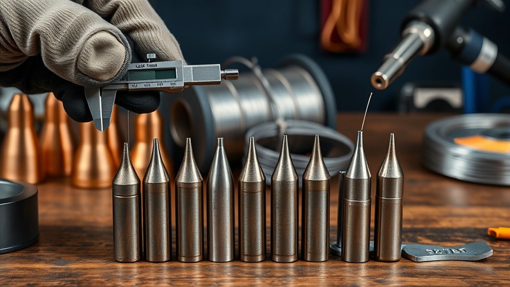
The wire diameter normally determines the nominal tip bore category. The welding process then affects the contact tip’s material, recess, heat exposure, wire stickout, and replacement interval.
Contact tip recess is the position of the tip end relative to the nozzle. Electrode extension is the wire length between the tip and the arc. Contact-tip-to-work distance, or CTWD, is the distance between the tip and the workpiece. These terms are related, but they do not describe the tip’s inner diameter.
According to Bernard and Tregaskiss, high-current pulsed and spray-transfer applications often use a recessed tip to protect it from arc heat. Many lower-current short-circuit applications use a flush tip and shorter electrode extension. Follow the gun and procedure recommendations because joint access, gas coverage, wire type, current, and nozzle design can change the correct position.
| Process condition | Typical tip-position concern | What to verify |
|---|---|---|
| Low-current short circuit | Often flush or near flush | Specified stickout, access, gas coverage, and burnback control |
| High-current pulse or spray | Often recessed to reduce radiant heat at the tip | Nozzle design, current, shielding gas, and specified CTWD |
| Deep or narrow joint access | An extended tip may sometimes be specified | Heat exposure, electrical safety, nozzle coverage, and manufacturer approval |
| Robotic production | Fixed and repeatable tip position | Tool center point, wire cast, programmed CTWD, and scheduled inspection |
Pro Tip: When the arc changes immediately after you install a new wire diameter, confirm the contact tip, drive-roll groove, liner range, and programmed wire size before adjusting voltage or wire feed speed.
Why Oversized and Undersized Tips Fail
What Happens When the Tip Is Too Small
An undersized or incorrectly manufactured bore can grip the wire too tightly. Friction rises as the tip heats, and the wire may drag, hesitate, shave, buckle at the feeder, or fuse inside the bore.
Possible signs include:
- Wire feeds normally with the tip removed but slows after the tip is installed.
- The drive rolls slip or create a bird’s nest.
- The wire repeatedly burns back into a new tip.
- Aluminum wire leaves shavings near the tip or liner.
- The wire cannot be hand-fed through a powered-off, removed tip without abnormal resistance.
What Happens When the Tip Is Too Large
An oversized or badly worn bore may allow the wire to contact the tip inconsistently. Current transfer can move from one contact point to another, increasing electrical resistance, tip temperature, start variation, and arc instability.
The wire may also move off center as it exits the tip. That movement matters most in robotic work, narrow joints, and applications that need a repeatable tool center point.
Do not diagnose an oversized tip from arc wander alone. A loose diffuser connection, damaged liner, excessive wire cast, poor work connection, unstable parameters, or magnetic arc blow can create similar symptoms.
How to Spot the Wrong Tip Size
| Symptom | Possible tip-related cause | Other checks | Corrective action |
|---|---|---|---|
| Wire stalls or surges | Tip too tight, dirty, burred, or overheated | Liner, cable bends, drive pressure, spool brake, and inlet guide | Install the correct new tip and correct feed-path resistance |
| Repeated burnback | Tight bore, worn bore, overheated tip, or poor electrical connection | Wire speed, burnback control, CTWD, liner, and drive rolls | Replace the tip, secure the diffuser connection, and correct the root cause |
| Arc wanders or starts inconsistently | Oversized, keyholed, or loose tip | Work clamp, wire cast, gun angle, joint magnetism, and parameters | Install and tighten the approved tip, then retest |
| Blue, purple, or black heat discoloration | Loose connection, high resistance, high heat load, or insufficient tip capacity | Gun duty cycle, diffuser, cooling, recess, amperage, and spatter buildup | Stop, allow cooling, inspect the connection, and replace damaged parts |
| Bore becomes oval or keyhole-shaped | Normal mechanical wear accelerated by wire cast, abrasiveness, or heat | Wire quality, tip material, alignment, and programmed gun angle | Replace the tip and review wear rate |
| Spatter increases | Worn tip, loose tip, or unstable current transfer | Voltage, wire speed, polarity, gas, CTWD, surface condition, and technique | Replace a defective tip, then tune the actual process cause |
Choose the Best MIG Contact Tip Material
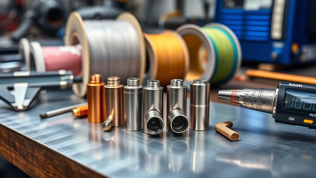
Tip material changes the balance among electrical conductivity, hardness, heat resistance, wear, and purchase cost. It does not change the need to select the correct wire-size marking and compatible tip geometry.
ABICOR BINZEL identifies electrolytic copper, copper-chromium-zirconium, and proprietary heavy-duty designs as common contact-tip material categories.
| Material or design | Main advantage | Main limitation | Typical use |
|---|---|---|---|
| Electrolytic copper, or E-Cu | High electrical and thermal conductivity | Softer and more prone to keyhole wear under severe heat or long arc-on time | General manual and light-to-medium-duty welding |
| CuCrZr, or copper-chromium-zirconium | Greater hardness, heat resistance, and shape retention | Normally costs more and has slightly lower conductivity than pure copper | High-amperage, abrasive-wire, automated, and high-duty-cycle work |
| Proprietary hardened or silver-enhanced design | May improve wear or arc-erosion resistance in the intended application | Performance claims and compatible wires vary by manufacturer | Production cells where validated tip life offsets the higher cost |
Copper vs. CuCrZr
Copper remains practical for ordinary manual welding because it transfers current well and is widely available. CuCrZr is harder and holds its bore shape better under high heat and long arc-on time, which makes it useful in production and robotic applications.
Do not assume that the harder material is always better. A correctly fitted copper tip may outperform a poorly fitted premium tip. Compare arc stability, burnback frequency, tip life, downtime, wire type, and total operating cost in the actual application.
Specialty Contact Tip Materials
Silver-enhanced, plated, or internally hardened tips are product-specific designs. Use the manufacturer’s published wire restrictions and life claims instead of treating every silver-colored tip as the same product.
Do not substitute a stainless steel tip unless your gun manufacturer explicitly lists one for the application. Contact-tip material and geometry must provide an approved electrical and mechanical connection.
Drawn vs. Drilled MIG Contact Tips
Drawn and drilled describe how the center bore is produced. They do not, by themselves, prove that one finished tip will create a better weld than another.
Drawn Tip Basics
A drawn tip is formed around a mandrel or through a drawing process. It can be economical and suitable for many manual applications. Its performance depends on bore consistency, surface finish, material, wire cast, and the quality of the electrical connection to the diffuser.
Check the manufacturer’s published tolerances and intended duty rather than assuming that every drawn tip has a rough or inaccurate bore.
Drilled Tip Advantages
A precision-drilled tip can provide tightly controlled bore geometry and a smooth wire path when it is manufactured well. Those features may help repeatability in automated welding, but they do not eliminate failures caused by poor wire, incorrect CTWD, a loose connection, liner drag, excessive heat, or bad parameters.
| Feature to compare | Why it matters |
|---|---|
| Published bore tolerance | Controls how consistently different tips fit the same wire |
| Internal surface finish | Affects drag, shaving, and wire deposits inside the bore |
| Tip material | Affects conductivity, heat resistance, and mechanical wear |
| Connection design | A secure seat reduces resistance and overheating |
| Verified service life | Shows how the tip performs with your wire, current, waveform, and duty cycle |
Set Tip Size for Manual and Robotic Welding
Manual and Semiautomatic Welding
For manual welding, begin with the tip marked for the wire size. This gives you the best chance of smooth feed without creating unnecessary clearance.
Replace the tip when its condition affects the process rather than changing it at an arbitrary number of hours. Wire type, amperage, gun angle, CTWD, duty cycle, joint reflection, and spatter exposure all change tip life.
Robotic and Automated Welding
Robotic welding adds repeatability requirements. A worn bore can shift the wire exit point and disturb the tool center point even before the tip fails completely.
Production cells should track:
- Wire package and cast
- Tip part number and material
- Arc-on time or parts welded
- Burnback frequency
- Keyhole or bore-wear pattern
- Arc-start consistency
- Tool-center-point movement
- Time spent changing tips
Some high-volume operations using low-cast solid wire from large drums test a tip one nominal size smaller. Bernard and Tregaskiss describe this as a production-specific option, while warning that undersizing can increase friction and burnback. Do not transfer that practice to a small-spool manual gun without manufacturer approval and a controlled trial.
Prevent Burnback, Spatter, and Arc Wander
Stop Burnback Early
Burnback occurs when the wire melts into or fuses with the contact tip. The tip may be involved, but common causes also include wire feed that is too slow, a CTWD that is too short, incorrect burnback control, liner drag, drive-roll slip, or unstable wire delivery.
- Turn off the power source.
- Remove the nozzle and inspect it for heavy spatter.
- Remove and replace a fused, burred, keyholed, or discolored contact tip.
- Confirm the new tip’s wire size and part number.
- Check that the tip seats tightly against the diffuser.
- Inspect the liner, guides, drive rolls, spool brake, and cable path.
- Restore the manufacturer’s recommended CTWD, wire speed, and burnback setting.
- Test the setup on scrap before continuing the job.
Warning: Repeated burnback is a symptom, not a normal reason to keep replacing tips. Stop and correct the feed, parameter, CTWD, or connection problem before another tip becomes damaged.
Tame Spatter Issues
A worn or loose contact tip can contribute to unstable current transfer and spatter, but tip size is only one possible cause. Check voltage, wire feed speed, polarity, shielding gas, CTWD, work connection, surface condition, and gun technique.
Keep the nozzle and diffuser clean enough to maintain gas flow. Correct shielding gas consumption and suitable gas flow rates help prevent porosity, but excess gas flow can also draw air into the shielding stream.
For self-shielded wire, gas flow does not apply, but the wire’s self-shielding capability still does not remove the need for the correct tip, polarity, drive system, and electrode extension.
Eliminate Arc Wander
Inspect a wandering arc in this order:
- Confirm the wire and tip size markings.
- Replace a keyholed or visibly worn tip.
- Tighten the tip and inspect the diffuser seat.
- Check the work clamp and current path.
- Keep CTWD and gun angle steady.
- Inspect wire cast, liner support, and cable bends.
- Review voltage, wire feed speed, transfer mode, and magnetic arc-blow conditions.
If the problem remains after a new matched tip and a sound feed path, do not continue downsizing the bore. The cause is likely elsewhere in the setup.
What Contact Tip Size Does Not Control
A MIG contact tip guides wire and transfers current. It does not independently determine weld size, penetration, shielding, or the correct settings for an unrelated cutting process.
- Weld size: Contact tip size does not replace joint design, procedure requirements, or correct fillet weld sizing.
- Machine capability: A multi-process welder still needs the correct gun, feeder, wire, polarity, and consumables for each process.
- Flux-core technique: Tip selection cannot compensate for incorrect polarity, electrode extension, or poor flux-core welding technique.
- Plasma consumables: A MIG contact tip is not a plasma cutting tip. Plasma amperage and consumables, torch standoff, and cutting gas selection follow a different process and manufacturer chart.
Frequently Asked Questions
How often should MIG contact tips be replaced?
Replace a contact tip when you find keyhole wear, an enlarged or rough bore, repeated burnback, unstable starts, erratic feeding, heavy discoloration, damaged threads, or a loose fit. There is no universal replacement interval because wire type, current, CTWD, duty cycle, and application heat change the wear rate.
Can one contact tip size work for multiple wire diameters?
Use the contact tip listed for the installed wire diameter. A larger tip may physically pass a smaller wire, but the extra clearance can reduce guidance and current-transfer consistency. Never assume that one tip covers several wire sizes unless the gun manufacturer explicitly lists that range.
Do gasless MIG wires need special contact tips?
Self-shielded flux-cored wire normally uses a tip marked for its nominal diameter and compatible with the gun. It may wear tips faster than copper-coated solid wire, so follow the wire and gun manufacturer’s guidance for tip material, drive rolls, polarity, and electrode extension.
Does contact tip wear affect welding penetration?
It can. A worn or loose tip may disturb wire feeding and current transfer, which can make the arc and bead less consistent. However, a penetration change also requires checking CTWD, wire speed, voltage, polarity, work connection, travel speed, joint preparation, and gun angle.
Are copper tips better than CuCrZr tips?
Copper tips provide excellent conductivity and suit many manual applications. CuCrZr tips are harder and resist heat and keyhole wear better, which often makes them useful for high-current, abrasive-wire, automated, or long-duty-cycle work. The better choice is the one that gives stable performance and acceptable total cost in your application.
What contact tip size should I use for .035 wire?
Start with the compatible .035-inch or 0.9 mm contact tip listed for your gun. Also confirm that the liner and drive-roll groove support .035-inch wire. Use a different bore only when the consumable manufacturer or a validated production procedure calls for it.
What contact tip should I use for .030 aluminum wire?
Use the aluminum-specific tip that your spool gun, push-pull gun, or MIG gun manufacturer lists for .030-inch aluminum wire. The tip is designed with additional bore clearance for aluminum. Pair it with the approved nonmetallic liner, smooth guides, U-groove rolls, and low drive pressure.
Are .023, .024, and .025 contact tips the same?
Not automatically. These markings may appear in different manufacturers’ 0.6 mm consumable systems, but their actual bores and external geometry can differ. Use the exact tip part number that your gun manual lists for the wire you installed.
Can I use a different brand of contact tip in my MIG gun?
Only when the replacement manufacturer explicitly lists the tip as compatible with your gun, diffuser, nozzle, wire size, and current rating. Matching wire-size markings do not guarantee matching threads, length, seat, outside diameter, or contact tip recess.
Conclusion
The normal starting rule is simple: use the contact tip that your gun manufacturer lists for the installed wire diameter. Then confirm the tip series, thread, length, material, liner, drive rolls, nozzle, recess, and gun rating.
Use a purpose-made aluminum tip for aluminum wire, and treat undersizing as a controlled production adjustment rather than a shortcut for manual welding. When burnback, spatter, feed drag, heat discoloration, or arc wander appears, inspect the whole feed and electrical system instead of replacing tips repeatedly without correcting the cause.
Sources
- Bernard and Tregaskiss: Tips for Choosing the Right Contact Tip — nominal size selection, bore fit, material choice, wear, and burnback guidance.
- ESAB: Feedability in GMAW Welding of Aluminum — aluminum contact-tip clearance, liners, drive rolls, and feeding systems.
- Bernard and Tregaskiss: Correct Contact Tip Recess Can Improve Welding Efficiency — contact tip recess, wire stickout, CTWD, and transfer-mode guidance.
- ABICOR BINZEL: Contact Tips for MIG/MAG Torches — copper, CuCrZr, heavy-duty designs, and aluminum-tip considerations.
- Lincoln Electric QUICKMIG 250/300 Operator’s Manual — matching the liner and contact tip to wire size and safe wire-loading precautions.