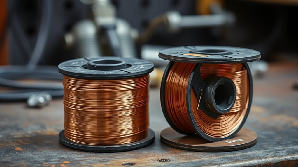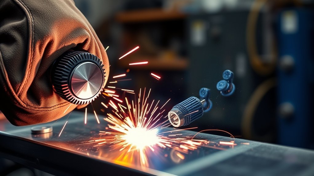
MIG wire speed issues can look similar even when they have different causes. A wire that hammers into the plate usually points to too much feed for the selected voltage, while wire that burns back into the contact tip often points to too little feed, too much voltage, or resistance in the feed path. The safest way to diagnose the problem is to restore a known baseline, test on matching scrap, and change one variable at a time.
Quick Answer
If the wire repeatedly stubs into the work and pushes the gun back, reduce wire speed or increase voltage slightly. If it melts back into the contact tip, increase wire speed, reduce voltage, or remove feed resistance. Confirm polarity, gas, stickout, travel speed, and consumable condition before blaming the dial.
Key Takeaways
- Wire feed speed and voltage must be tuned together; either one can make the arc appear too harsh, too long, or unstable.
- Stubbing usually means wire feed is too high for the voltage, while burn-back often means feed is too low, voltage is too high, or the wire is hesitating.
- Spatter, porosity, and poor fusion can also come from wrong polarity, dirty metal, bad gas coverage, excessive stickout, or poor travel technique.
- A worn tip, dirty or kinked liner, incorrect drive roll, excess spool drag, or loose work connection can mimic a bad speed setting.
- Use the welder’s chart as a starting point, test on matching scrap, and adjust only one control at a time.
At a Glance
| Time Required | About 10–20 minutes for a basic setup check and test beads |
| Difficulty | Beginner to intermediate |
| Tools Needed | Welder manual or door chart, matching scrap, PPE, wire brush or grinder, MIG pliers, and basic hand tools |
| Cost | Usually no cost for adjustment; replacement tips, liners, or drive rolls vary by machine |
What’s in This Article
- How MIG Wire Speed Affects the Arc
- Checks to Make Before Changing Wire Speed
- Signs Your Wire Speed Is Too Fast
- Signs Your Wire Speed Is Too Slow
- How Voltage and Wire Speed Work Together
- How Wire Speed Affects Amperage and Penetration
- Adjusting for Material, Wire, Position, and Transfer Mode
- Step-by-Step Diagnostic Process
- Feed-System Problems That Mimic a Bad Setting
- What to Do When Wire Speed Is Too Fast or Too Slow
- Best Practices for Consistent Results
- Frequently Asked Questions
How MIG Wire Speed Affects the Arc

In conventional constant-voltage MIG welding, wire feed speed mainly controls welding current and deposition rate. As you raise the feed speed, the machine normally supplies more current to melt the additional wire. Voltage mainly changes arc length and influences bead width and profile. Travel speed, stickout, wire diameter, shielding gas, polarity, joint design, and transfer mode also affect the result.
This relationship explains why a wire speed number cannot be judged by itself. A feed rate that works well at one voltage may stub into the plate at a lower voltage or burn back at a higher voltage. Synergic machines link several settings automatically, but you still need the correct program, wire diameter, gas, and material selection.
On a conventional constant-voltage MIG welder, think of wire feed speed as the main current and deposition control, and voltage as the main arc-length and bead-profile control.
Start with the chart inside the welder or the manufacturer’s procedure guide. A chart accounts for the machine’s output range, wire diameter, and expected material thickness better than a universal voltage-and-speed pair. For additional starting points, see this MIG welding wire speed and voltage chart.
Checks to Make Before Changing Wire Speed
Before turning the wire speed dial, confirm that the machine and feed system are set up correctly. A bad ground, wrong polarity, mismatched contact tip, or restricted liner can produce the same symptoms as an incorrect feed setting.
Warning: Turn off and disconnect the welder before touching the spool, drive rolls, liner, contact tip, or internal connections. Restore power only for a controlled test weld, and follow welding PPE and ventilation precautions, including a suitable helmet, gloves, flame-resistant clothing, and fume control.
- Confirm the process and polarity: Solid-wire MIG commonly uses DCEP, but flux-cored wires vary. Follow the wire label and machine manual, and verify the correct MIG wire spool and wire type.
- Match the feed parts: Use the correct drive-roll groove, liner size, and contact tip for the wire diameter and wire type.
- Check shielding gas: Confirm the correct gas, adequate cylinder pressure, an open valve, and unobstructed nozzle flow.
- Clean the joint and work-clamp area: Remove rust, paint, oil, scale, and coatings that can destabilize the arc or block current flow.
- Set spool drag and drive-roll tension: The spool should stop without freewheeling, while the rolls should feed without crushing or shaving the wire.
- Straighten the gun cable: Tight loops and kinks add friction, especially with soft aluminum wire.
- Hold a consistent stickout: About 3/8 inch is a common starting point for short-circuit MIG on mild steel, but the correct distance changes with the process and procedure.
Note: A wrong speed setting produces a repeatable arc problem. A feed-system fault often causes surging, random hesitation, or a speed that changes as you bend the gun cable.
How to Recognize When Your Wire Speed Is Too Fast
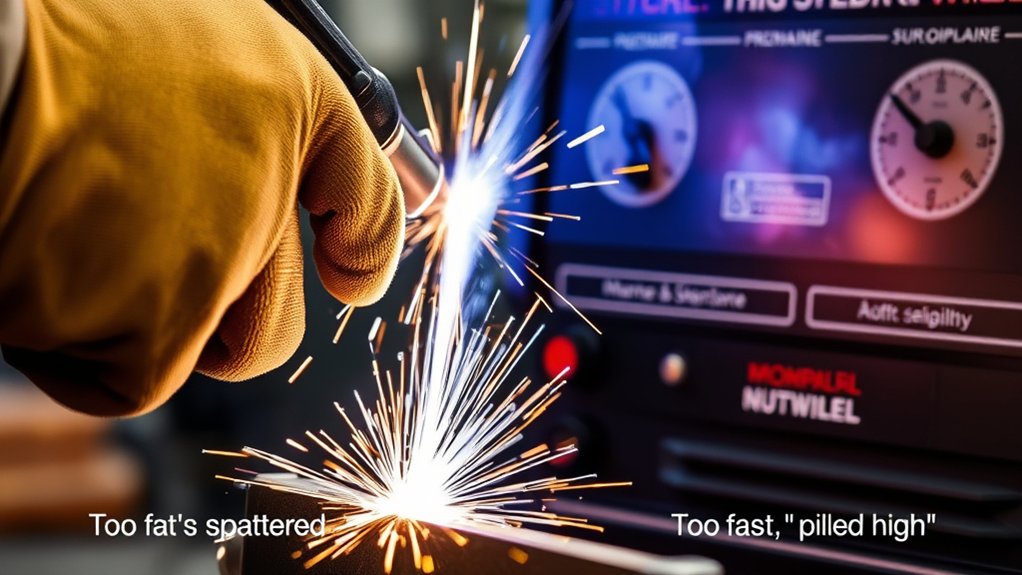
Wire speed is too fast when the electrode reaches the work faster than the selected voltage can melt it smoothly. The wire may strike the plate, push the gun backward, or create a hard, explosive popping sound. This condition is often described as stubbing.
Too much feed can also raise current enough to overheat or burn through thin metal. However, more current does not guarantee good fusion. A badly mismatched arc can produce heavy spatter, an overly convex or wide bead, poor toe tie-in, and inconsistent penetration.
Increased Spatter and Harsh Popping
Heavy spatter can come from wire feed that is too high for the voltage, but it is not proof by itself. Low voltage, excessive stickout, wrong polarity, dirty metal, poor gas coverage, and an extreme gun angle can cause similar spatter.
- Wire repeatedly hits the plate: Reduce wire speed slightly or increase voltage slightly.
- Arc is harsh but the wire does not stub: Check voltage, stickout, polarity, gas, and travel angle before making a large speed change.
- Spatter appears suddenly after the gun cable moves: Inspect the liner, tip, and drive system for intermittent drag.
Burn-Through and Poor Bead Control
On sheet metal, excessive feed can raise current and total heat enough to open a hole, especially when travel speed is slow or the joint has a gap. The bead may also become too wide, lumpy, or difficult to keep centered. Lower the feed in a small step, retune voltage if needed, and use short test beads on scrap of the same thickness.
For thin automotive panels, controlling fit-up, tack spacing, and cooling time matters as much as the wire speed. This guide to welding sheet metal on a car covers those additional heat-control steps.
Identifying Signs Your Wire Speed Is Too Slow
Wire speed is too slow when the selected voltage burns the electrode back faster than the feeder replaces it. The arc may lengthen, surge, or extinguish, and the wire may fuse to the contact tip. Current can also fall too low for the joint, leaving a narrow, convex bead with weak tie-in at the toes.
Inconsistent Arc Stability
A slow feed rate can make the arc feel weak or erratic. Look for a combination of symptoms rather than one clue:
- Long or wandering arc: The wire melts well above the puddle instead of transferring at a steady distance.
- Narrow, crowned bead: The bead sits high with poor wetting into the base metal.
- Poor fusion: The weld may look attached on the surface but fail to tie into the joint edges or root.
- Frequent arc outages: The wire burns away faster than it advances, then restarts as more wire reaches the work.
Increase wire speed in a small step or reduce voltage slightly, then make another test bead while keeping travel speed and stickout steady.
Frequent Wire Burn-Back
Burn-back occurs when the arc travels up the electrode and fuses the wire to the contact tip. A feed setting that is too low can cause it, but so can a worn or oversized tip, a kinked or dirty liner, excess spool drag, weak drive-roll pressure, a tangled spool, or a feed motor that hesitates.
Cut off the fused wire, replace a damaged tip, and inspect the full feed path before raising wire speed repeatedly. If burn-back occurs only when you release the trigger, check the machine’s run-in or burn-back control if it has one, and follow the owner’s manual.
Warning: Stop and inspect the gun when burn-back repeats. Continuing to weld with a fused or damaged contact tip can worsen feeding problems and damage consumables.
How Voltage Settings Affect MIG Wire Speed and Weld Quality
Voltage and wire feed speed must be balanced. On a conventional MIG welder, you normally choose a wire feed speed that provides enough current and filler for the material, then adjust voltage until the arc is stable and the bead wets into the joint without excessive spatter.
| Condition | Typical Arc Clue | Typical Bead Clue | First Correction |
|---|---|---|---|
| Feed too high or voltage too low | Wire stubs, gun pushes back, harsh popping | Spatter, convex or irregular bead, poor tie-in | Lower feed slightly or raise voltage slightly |
| Feed too low or voltage too high | Long, erratic arc or burn-back | Narrow bead, undercut, inconsistent fusion | Raise feed slightly or lower voltage slightly |
| Travel speed too fast | Arc may sound normal | Narrow bead with poor toe tie-in | Slow travel without dwelling |
| Travel speed too slow | Large, fluid puddle | Overly wide bead or burn-through | Increase travel speed |
| Gas or contamination problem | Unstable or rough arc | Porosity, pinholes, soot, or inclusions | Fix gas coverage and clean the metal |
Do not use one voltage-and-wire-speed pair as a universal rule. Wire diameter, metal thickness, shielding gas, joint design, welding position, transfer mode, and the machine’s calibration all change the correct combination.
How Wire Speed and Amperage Impact Weld Quality
On a constant-voltage MIG machine, raising wire feed speed normally raises welding current because the power source must melt more electrode each minute. Higher current can increase deposition and penetration, while lower current can leave a narrow bead with poor fusion. MIG current is controlled differently from the fixed-current approach shown in a stick welding amperage chart, and the relationship is not identical across every wire diameter, gas, transfer mode, or machine.
Stickout also changes the result. A longer electrical stickout heats more wire before it reaches the arc and changes effective current and penetration. That is why you should hold the gun at a consistent distance while tuning the controls.
Travel speed remains a separate variable. Moving too fast can cause a narrow bead and incomplete tie-in even when wire feed and voltage are correct. Moving too slowly can create an oversized puddle, excess heat, or burn-through. Use these principles when learning how to weld faster without losing weld quality. For critical or load-bearing work, appearance alone is not enough; use an approved welding procedure and the inspection or testing required for the job.
How to Adjust Wire Speed Based on Material, Wire, and Position
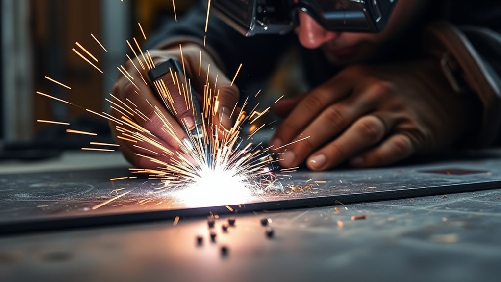
The correct wire speed depends on more than material thickness. Use the procedure chart for the exact wire, gas, polarity, and transfer mode, then fine-tune on matching scrap.
- Mild steel with solid wire: Start with the machine chart. Short-circuit transfer on thin steel commonly uses a short stickout and moderate settings that limit burn-through.
- Flux-cored wire: Follow the wire manufacturer’s polarity and stickout requirements. Self-shielded and gas-shielded wires do not share one setup. See these flux-core welding tips for process-specific technique.
- Stainless steel: Use the recommended stainless wire and shielding gas. Do not copy a mild-steel setting without checking the chart for the selected filler and joint.
- Aluminum: Soft wire magnifies feed resistance. Use the recommended drive rolls, liner, contact tip, and spool gun or push-pull system when required. A feed hesitation can look like a speed-setting error.
- Vertical and overhead welds: Do not automatically raise wire speed. These positions often need lower voltage and current than the same weld in the flat position so the puddle stays smaller and easier to control.
- Galvanized steel: Remove coating from the weld area when the job and applicable rules allow, control fumes, and use suitable ventilation. The zinc coating can change arc behavior and create hazardous fumes; review safe methods for MIG welding galvanized steel.
Pro Tip: Record wire type and diameter, gas, polarity, material thickness, joint, position, voltage, wire speed, stickout, and travel technique after a successful test. Your own verified setup notes are more useful than a generic number copied from another machine.
Troubleshooting Wire Speed Issues: A Step-by-Step Process
- Return to a known baseline: Use the door chart, owner’s manual, or wire procedure sheet for the material thickness and wire diameter.
- Prepare matching scrap: Use the same metal type, thickness, surface condition, joint type, and position as the real work.
- Stabilize your technique: Hold the same stickout, work angle, travel angle, and travel speed for each test.
- Make a short test bead: Listen to the arc and watch whether the wire stubs into the plate, burns toward the tip, or feeds smoothly.
- Change one control: Adjust wire speed or voltage by one small increment, not both at once.
- Repeat the bead: Compare spatter, bead profile, toe tie-in, penetration evidence, and arc consistency.
- Check the feed system: If the speed surges or the same settings produce different results, stop adjusting the dial and inspect the spool-to-tip path.
- Confirm the repair: Make more than one test bead. For important welds, use the procedure, destructive test, or inspection method required for the application.
Note: The familiar “sizzling bacon” sound applies mainly to a well-tuned short-circuit steel arc. Spray, pulsed MIG, aluminum, and some flux-cored procedures sound different, so use sound as a clue rather than a pass-or-fail test.
Products Worth Considering
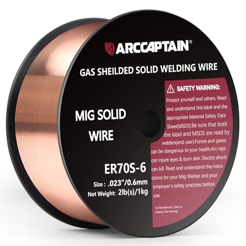
High-quality: ARCCAPTAIN's ER70S-6 mig welding wire .023" meets industry standards(Net Weight: 2lbs), ensuring consistent performance, superior strength. With its smooth feeding and stable welding parameters, you can achieve optimal penetration, high deposition rates, and exceptional overall welding performance.

ER308L WIRE: A low-carbon stainless steel wire engineered to minimize intergranular carbide precipitation. This enhances corrosion resistance without the need for stabilizers, making it ideal for critical applications.

High-quality: ARCCAPTAIN's ER70S-6 mig welding wire .030" meets industry standards(Net Weight: 2lbs), ensuring consistent performance, superior strength. With its smooth feeding and stable welding parameters, you can achieve optimal penetration, high deposition rates, and exceptional overall welding performance.
Feed-System Problems That Mimic a Bad Wire Speed Setting
If the wire feed is uneven with no arc, or the speed changes when you move the gun cable, the problem is probably mechanical or electrical rather than a simple dial setting. Work through the feed path in order.
- Spool and hub: Make sure the spool turns in the correct direction, the wire is not crossed, and the hub brake is not too tight or too loose.
- Drive rolls: Confirm the groove size and type match the wire. Use only enough pressure to feed reliably without flattening, shaving, or deforming it.
- Inlet and outlet guides: Align them with the roll groove and check for wear, grooves, or packed debris.
- Liner: Replace a kinked, dirty, rusty, incorrectly sized, or badly trimmed liner. Keep the gun cable as straight as practical during testing.
- Contact tip: Use the correct size. Replace a worn, oval, loose, spatter-blocked, or burn-back-damaged tip.
- Wire condition: Replace rusty, contaminated, or badly cast wire that does not feed smoothly.
- Work connection: Clamp to clean metal and inspect loose or damaged cables. A poor connection destabilizes the arc even when feed speed is steady.
- Motor and controls: If the wire still surges with the gun straight and consumables verified, stop using the machine and follow the service manual or contact a qualified technician.
For broader electrical and mechanical checks, use this MIG welder troubleshooting guide. If the wire feeds but no arc starts, inspect the ground clamp and current path before changing feed speed.
What to Do if Your Wire Speed Is Too Fast or Too Slow
Products Worth Considering

welding tools Package List - 2pcs Snap on gas nozzles, 2pcs gas diffusers M6 internal thread, 2pcs Red copper contact tips 0.024''(0.6mm), 5pcs Copper contact tips 0.030''(0.8mm for long continuous welding), 3pcs Copper welding contact tips 0.040''(1.0mm for spot welding). Totally 14pcs in this welder kit of 15AK MIG MAG welding torch consumable parts set.
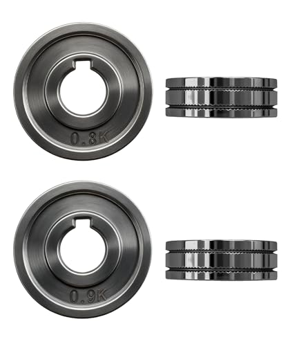
Package Contents: You will get 2* Drive Roll

Package list: 30 pieces of 0.030 inch mig welder tips.
If the Wire Speed Is Too Fast
- Confirm the voltage is not below the chart’s starting range.
- Reduce wire feed speed by one small increment.
- Keep stickout and travel speed steady while making another test bead.
- If the wire still stubs, raise voltage slightly within the procedure range instead of continuing to reduce current.
- Stop if thin metal overheats; improve fit-up, shorten the weld time, and allow cooling between tacks.
If the Wire Speed Is Too Slow
- Confirm the voltage is not above the chart’s starting range.
- Increase wire feed speed by one small increment.
- If burn-back continues, inspect the tip, liner, drive rolls, spool drag, and gun-cable bends.
- Replace damaged consumables before making more setting changes.
- Retest on matching scrap and confirm the bead ties into both sides of the joint.
If neither adjustment produces a stable arc, check polarity, gas, wire type, contact tip-to-work distance, surface cleanliness, and travel technique. A general list of MIG welding problems and solutions can help separate feed issues from gas, contamination, and technique problems.
Best Practices for Consistent Wire Speed Results
- Use the chart first: Begin with the machine or wire manufacturer’s setting, not a universal inches-per-minute range. Model-specific references, such as a Lincoln welder settings chart, are useful only when they match your machine, wire, gas, and material.
- Keep the wire path clean: Inspect the spool, guides, drive rolls, liner, tip, and nozzle before a major job.
- Match consumables: The tip, liner, and drive roll must fit the wire diameter and material.
- Maintain steady stickout: Around 3/8 inch is a common mild-steel short-circuit starting point, but spray, pulsed, aluminum, and flux-cored procedures may require a different distance.
- Clean the work and clamp area: Solid MIG wire is less tolerant of rust, oil, paint, and scale than many flux-cored processes.
- Control gun angle and travel speed: Extreme angles and inconsistent motion change penetration, spatter, and bead shape.
- Change one variable at a time: This makes the cause-and-effect relationship clear.
- Respect duty cycle: If the machine overheats or output changes after prolonged welding, stop and follow the cooling and duty-cycle instructions in the manual.
Note: Porosity is usually a shielding-gas or contamination problem, not a wire-speed problem. Check gas flow, drafts, nozzle blockage, leaks, stickout, and surface cleanliness before changing feed speed.
Frequently Asked Questions
How do I know if my MIG wire speed is too high?
The clearest sign is wire stubbing into the work and pushing the gun back. You may also hear harsh popping and see heavy spatter, a convex or irregular bead, and burn-through on thin metal. Low voltage can create the same balance problem, so compare both settings with the machine chart.
What happens if wire feed speed is set too fast?
The electrode can reach the plate faster than the arc melts it, causing stubbing, spatter, poor arc starts, a rough bead, or burn-through. Excess current may add heat, but a badly mismatched arc can still produce poor toe tie-in or inconsistent penetration.
What happens if MIG wire speed is too slow?
The arc may become long and unstable, current may be too low for the joint, and the bead may be narrow or crowned with poor tie-in. The wire can also burn back into the contact tip, especially when voltage is high for the selected feed rate.
Why does the wire burn back even after I increase the speed?
A mechanical feed problem may be slowing the wire before it reaches the tip. Check spool drag, drive-roll pressure, roll size, liner condition, cable bends, contact-tip size, and wire condition. Burn-back at trigger release may also involve a run-in or burn-back control on machines that provide those adjustments.
What should a correctly tuned MIG arc sound like?
A short-circuit steel arc often makes a steady, rapid sizzling sound. Harsh stubbing, slow explosive pops, or repeated surging suggest a mismatch or feed problem. Spray, pulsed MIG, aluminum, and flux-cored procedures sound different, so also judge the puddle and bead.
What happens when I move the MIG gun too fast?
Excessive travel speed can leave a narrow, inconsistent bead with poor toe tie-in and insufficient penetration. Correct wire speed cannot fully compensate for bad travel speed, so keep the gun moving steadily and watch the leading edge of the puddle.
What safety risks should I control while troubleshooting a MIG welder?
Control electric shock, arc radiation, burns, fire, noise, and welding fumes. Wear proper PPE, remove combustibles, use suitable ventilation or local exhaust, and disconnect power before servicing the feed system. Follow the welder manual and workplace safety requirements.
Can wire speed fix every MIG welding problem?
No. Dirty metal, a poor work connection, wrong polarity, bad gas coverage, a worn tip, a damaged liner, incorrect drive rolls, excessive stickout, and poor travel technique can produce similar symptoms. Diagnose the whole system before repeatedly changing wire speed.
Safety Disclaimer: This article is for informational purposes only and does not replace hands-on training, an approved welding procedure, the equipment manual, or professional guidance. Use proper PPE, ventilation, fire prevention, and electrical safety practices.
Conclusion
MIG wire speed diagnosis becomes easier when you separate balance problems from feed-system faults. Wire that stubs into the plate usually needs less feed or more voltage, while wire that burns back usually needs more feed, less voltage, or a smoother path through the gun. Start from the manufacturer’s chart, test on matching scrap, and change one variable at a time. Those habits produce cleaner, safer, and more consistent welds.
Sources
- Miller: MIG Welding — Setting the Correct Parameters — wire feed, voltage, travel-speed, and bead-diagnosis guidance
- Miller: Understanding the Basics of MIG Welding for Mild Steel — setup, polarity, tension, gas, stickout, position, and technique
- Miller: Choosing MIG Welding Consumables — liner, contact-tip, and wire-feed troubleshooting
- Miller: How to Successfully MIG Weld Aluminum — aluminum feeding systems, burn-back, tip distance, and setup
- OSHA: Welding, Cutting, and Brazing Hazards and Solutions — fumes, ultraviolet radiation, burns, electrical hazards, and PPE