
A MIG welder that powers on but will not feed wire usually has resistance or a mismatch somewhere between the spool and the contact tip. Start with the simple checks: wire speed, spool drag, drive roll size and pressure, gun-cable bends, liner condition, and the contact tip. Only move to the trigger circuit or feeder motor after the wire path checks out.
Quick Answer
If your MIG welder is not feeding wire, remove the contact tip, straighten the gun cable, and watch the drive rolls while pressing the trigger. Rolls that turn without moving wire point to tension, roll, spool, or liner trouble. Silent rolls point to power, thermal protection, trigger, wiring, or motor trouble.
Key Takeaways
- Check the spool, drive rolls, tension, liner, gun cable, and contact tip before blaming the feeder motor.
- Match the drive roll groove, liner, and contact tip to both the wire diameter and wire type.
- Use only enough drive roll pressure to feed smoothly without slipping, flattening, or shaving the wire.
- If feeding improves with the contact tip removed or the gun cable straight, the restriction is likely in the tip, liner, or cable path.
- Disconnect input power before opening the machine or touching internal wiring, and leave board-level repairs to qualified service personnel.
At a Glance
| Time Required | 15–45 minutes for basic diagnosis |
| Difficulty | Beginner for feed-path checks; qualified service recommended for internal electrical faults |
| Tools Needed | Owner’s manual, flashlight, side cutters or MIG pliers, clean cloth, and dry compressed air only if the gun manual allows it |
| Cost | Often $0 for adjustment or cleaning; replacement consumable cost varies by welder and gun model |
Warning: Turn the welder off and disconnect input power before removing covers, touching wiring, or servicing internal parts. During a powered wire-feed test, point the gun away from yourself and others, keep hands clear of the rolls, and wear eye protection because the wire can exit suddenly.
Common Causes of MIG Welder Wire Feeding Problems
Most wire-feed failures fall into one of three groups: the feeder does not turn, the feeder turns but cannot pull wire from the spool, or the feeder pushes wire until it reaches a restriction in the gun. Watching what happens when you press the trigger is the fastest way to narrow the problem.
| Symptom | Most Likely Causes | First Check |
|---|---|---|
| No sound and no roll movement | No input power, wire speed at zero, thermal protection active, loose gun connection, bad trigger, fuse, control, or motor fault | Power, settings, cooling time, gun connection, and trigger |
| Rolls turn but wire does not move | Too little pressure, wrong roll groove, worn or dirty rolls, crossed wire, or excessive spool brake drag | Spool path, roll size, roll condition, and tension |
| Wire moves, then stalls or stutters | Blocked contact tip, dirty or kinked liner, sharp cable bend, excessive roll pressure, or damaged wire | Remove the contact tip and straighten the cable |
| Wire birdnests near the feeder | Restriction after the rolls, too much roll pressure, a gap at the gun inlet, or the wrong drive roll for soft wire | Tip, liner, gun inlet, and roll type |
| Wire feeds but there is no arc | Work lead, gun power connection, contactor, polarity, or output circuit problem | Use the separate wire-feeds-but-no-arc troubleshooting steps |
If the entire machine behaves abnormally, not just the feeder, use a broader MIG welder troubleshooting guide before replacing wire-feed parts.
How the MIG Wire Feeding System Works
The feed system is a chain. The spool releases wire, the drive rolls grip it, the inlet and outlet guides keep it aligned, the liner supports it through the gun cable, and the contact tip guides the wire while transferring welding current. A mismatch or restriction at any point can show up as slipping, chatter, birdnesting, burnback, or an unstable arc.
The drive rolls must match the wire diameter and type. The pressure arm must provide enough grip without crushing the wire. The spool brake must prevent overrun without making the motor fight the spool. The liner must be the correct size and length, and the gun cable should remain as straight as practical during testing.
Once the wire feeds normally, use the broader MIG welding problems and solutions guide for arc, bead, porosity, or penetration issues that are not caused by the feed path.
A wire feeder works only as well as the most restrictive point between the spool and the contact tip.
Check the Drive Rolls and Match the Groove
Dirty, worn, misaligned, or mismatched drive rolls can slip on the wire or deform it. Confirm the size marking on the roll, place the wire in the correct groove, and remove metallic dust from the roll and guide area. Replace a roll that is rusty, chipped, heavily worn, or unable to grip evenly.
| Wire Type | Typical Drive Roll | Why |
|---|---|---|
| Solid steel wire | Smooth V-groove | Grips hard wire without excessive marking |
| Flux-cored or metal-cored wire | Knurled V-groove when specified by the equipment or wire maker | Adds grip at lower pressure, but excessive pressure can still crush cored wire |
| Aluminum wire | Smooth U-groove, usually with a polymer liner | Supports soft wire without shaving or pinching it |
Manufacturer guidance commonly uses smooth V-groove rolls for solid steel wire, knurled V-groove rolls for many cored wires, and U-groove rolls for aluminum. Aluminum also benefits from a spool gun or push-pull system when a standard push setup cannot feed it reliably. See Miller’s drive-roll and aluminum-feeding guidance and ESAB’s aluminum wire-delivery guide.
Note: Shielding gas problems can cause porosity or an unstable arc, but they do not normally stop the feeder from turning. Use the correct shielding gas for mild-steel MIG welding after the wire-feed path is working.
Set Wire Feed and Spool Tension Correctly
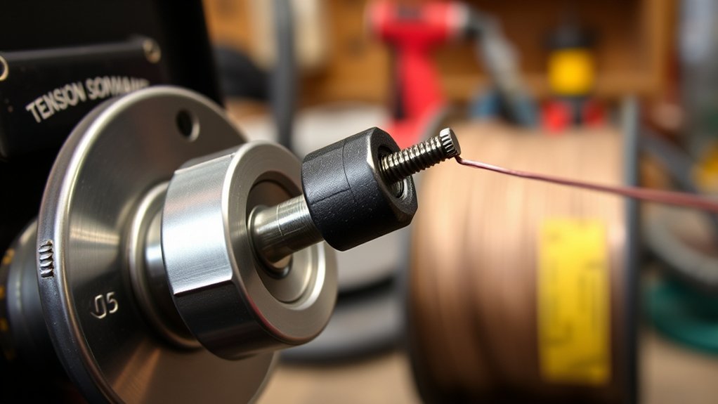
Drive roll tension controls how hard the rolls press on the wire. Too little pressure causes slipping. Too much can flatten solid wire, crush cored wire, shave aluminum, accelerate liner contamination, and make a downstream jam turn into a birdnest.
Use the procedure in your welder manual because tension scales differ by machine. A safe general method is to remove the contact tip, straighten the cable, start with low pressure, and increase it only until the wire feeds steadily without slipping. Do not keep tightening the pressure arm to force wire through a blocked tip or liner.
Pro Tip: If the rolls leave deep grooves, copper flakes, or a visibly flattened section on the wire, stop and reduce pressure. Then confirm the roll groove and wire diameter match.
| Adjustment | Correct Result | Wrong Result |
|---|---|---|
| Drive roll pressure | Steady feed with minimal marking | Slipping when too low; deformation or shavings when too high |
| Spool brake or hub tension | Spool stops without overrunning when the trigger is released | Loose coils when too low; motor strain or slipping when too high |
| Gun cable routing | Broad curves and a straight path during testing | Extra friction at tight bends or coils |
The Lincoln Electric Handy MIG manual instructs users to match the roll and contact tip to the wire, straighten the gun cable while feeding, and adjust pressure only until the wire feeds properly.
How to Identify and Fix Liner Problems
The liner guides and supports the wire from the feeder to the gun neck. Dirt, copper flakes, rust, a kink, a tight bend, the wrong inside diameter, or incorrect trim length can add enough friction to stop the wire even when the feeder motor and drive rolls work.
A liner problem is especially likely when the wire feeds with the gun laid straight but stalls when the cable is bent. The problem may also appear as chatter, an erratic arc, repeated burnback, or birdnesting close to the feeder.
Use the full wire-feed troubleshooting overview together with your gun manual when liner style, trim length, or gun connection details differ from the general steps below.
Inspecting Liner Condition
- Disconnect power: Turn the machine off and unplug it before removing consumables or releasing the wire.
- Remove the contact tip: A blocked or undersized tip can mimic a liner problem.
- Straighten the cable: Lay the gun cable in a broad, straight line and look for crushed, sharply bent, or damaged areas.
- Check manual feed resistance: With the pressure arm released and the wire safely controlled, a clean, straight section of correctly sized wire should move through the liner without hard spots. Do not yank it with pliers.
- Inspect the inlet and outlet guides: A gap, burr, or misalignment near the rolls gives the wire room to buckle.
- Clean only as approved: Many manufacturers allow the liner to be blown out gently with dry compressed air. Follow the gun manual and avoid solvents or oily products unless the manufacturer specifically approves them.
Miller notes that kinks and improper liner sizing can cause erratic feeding, while Bernard and Tregaskiss warn that a liner trimmed too short or too long can cause birdnesting and other feed problems. Review Miller’s MIG consumable guidance and Bernard and Tregaskiss liner installation steps.
Replacing Damaged Liners
Replace the liner when it is kinked, worn, rusty, separated, badly contaminated, or still restrictive after approved cleaning. Choose the liner range listed for your wire diameter and wire type. Aluminum commonly uses a polymer liner, while steel wire often uses a steel liner.
| Finding | Action |
|---|---|
| Visible kink, crushed cable, or broken liner | Replace the damaged liner or gun component |
| Heavy debris or rough feed that improves after cleaning | Clean as the manual allows, then monitor; replace if drag returns |
| Wrong liner range or material | Install the manufacturer-specified liner |
| Liner trimmed too short or too long | Replace or retrim only according to the gun’s gauge and instructions |
Keep the gun straight during installation and use the supplied trim gauge or the exact trim dimension in the gun manual. A generic trim length is not safe because gun and consumable systems differ.
When to Replace a Worn or Blocked Contact Tip
The contact tip must match the wire diameter and allow the wire to move freely while maintaining electrical contact. Replace it when the bore is blocked by burnback or spatter, the wire catches inside it, the opening is enlarged or oval, the tip is badly overheated, or the threads are damaged.
- Remove the tip and test feed: If the wire feeds normally with the tip removed, the tip is blocked, damaged, or the wrong size.
- Match the marking: A .035-inch wire normally uses a .035-inch contact tip unless the gun or wire manufacturer specifies otherwise.
- Inspect for keyholing: An enlarged or oval bore can produce poor current transfer and arc instability even if the wire still moves.
- Do not overtighten: Install the replacement according to the gun manual so the threads and diffuser are not damaged.
Note: Fillet weld sizing and heat-input planning affect weld design, but they do not diagnose a stopped feeder. Use the separate maximum fillet weld size guide only after the wire feeds and the machine is welding normally.
Products Worth Considering

Package list: 30 pieces of 0.030 inch mig welder tips.

20Pcs Contact Tip .023'' Ø0.6mm

1. Package Includes 30 Premium Quality .023” (Ø0.6mm)welding Tips.
Check the Spool, Gun Cable, Trigger, and Feeder Motor
If the rolls, tension, liner, and contact tip look correct, work backward through the remaining system.
Check the Spool and Wire Path
- Confirm the wire comes off the spool in the direction shown in the welder manual.
- Make sure the wire is not crossed under another wrap, snagged on the spool edge, rusty, kinked, or unwinding loosely.
- Set the spool brake just tight enough to stop overrun after the trigger is released.
- Check that the wire enters the inlet guide, sits in the drive-roll groove, and enters the gun connector without a large gap.
Check Thermal Protection and the Trigger
There is no universal MIG welder reset procedure. If the machine stopped after heavy use, allow it to cool with its air openings clear. Many machines use automatic thermal protection that restores output after the internal temperature returns to normal. Check the duty-cycle and indicator-light instructions in your manual.
If the machine is cool and the rolls remain silent, reseat the gun connection and inspect the trigger cable or plug for visible damage. A trigger, fuse, control board, or motor test may require model-specific electrical procedures.
Check the Feeder Motor and Controls
Do not probe a live circuit unless you are trained and the service manual gives the procedure. Disconnect power before opening the cabinet. If the machine has correct input power, is not overheated, and still has no roll movement or gas flow when the trigger is pressed, contact an authorized service center.
Warning: Welding equipment can contain hazardous voltage after the outer cover is removed. The Lincoln manual directs users to disconnect input power and have qualified personnel perform internal maintenance and troubleshooting. OSHA also identifies electrical shock, burns, eye damage, and fumes as welding hazards; use proper work practices and PPE.
Choosing and Storing Quality Welding Wire
Wire condition matters because the feeder must push it through several close-fitting parts. Use wire with a consistent labeled diameter, a clean surface, and an evenly wound spool. Avoid wire with rust, oil, deep kinks, crushed sections, loose coils, or heavy shop dust.
MIG wire is not the same consumable as a stick-welding electrode. The related welding rod guide applies to stick-welding electrodes, while a MIG setup must match the continuous wire to its drive rolls, liner, and contact tip.
Products Worth Considering
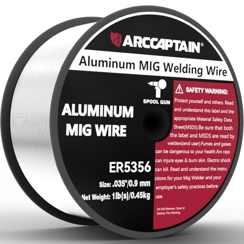
Smooth Welding Experience: With ARCCAPTAIN ER5356 Aluminum Welding Wire, expect smooth and stable arc characteristics, ensuring easy control and excellent weld bead appearance

ER308L WIRE: A low-carbon stainless steel wire engineered to minimize intergranular carbide precipitation. This enhances corrosion resistance without the need for stabilizers, making it ideal for critical applications.

High-quality: ARCCAPTAIN's ER70S-6 mig welding wire .030" meets industry standards(Net Weight: 10lbs), ensuring consistent performance, superior strength. With its smooth feeding and stable welding parameters, you can achieve optimal penetration, high deposition rates, and exceptional overall welding performance.
Wire Diameter Consistency
Check the spool label and confirm the same diameter appears on the drive roll, contact tip, and approved liner range. A mismatch can cause slipping, excess drag, poor electrical contact, or repeated burnback.
Wire Surface and Storage Matter
Store wire in a clean, dry area and keep it covered when the machine will sit unused. Replace visibly rusty or contaminated wire rather than forcing it through the liner. A dry wire-cleaning pad may help with light shop dust when the wire or equipment maker permits it, but do not apply oil or unapproved lubricant to the wire path.
Supplier Labeling and Compatibility Matter
Buy wire and consumables from a source that provides clear diameter, alloy, process, and polarity information. Reliable labeling makes it easier to match the roll, tip, liner, shielding gas, and machine settings, reducing avoidable downtime.
Essential Maintenance Tips for Smooth Feeding
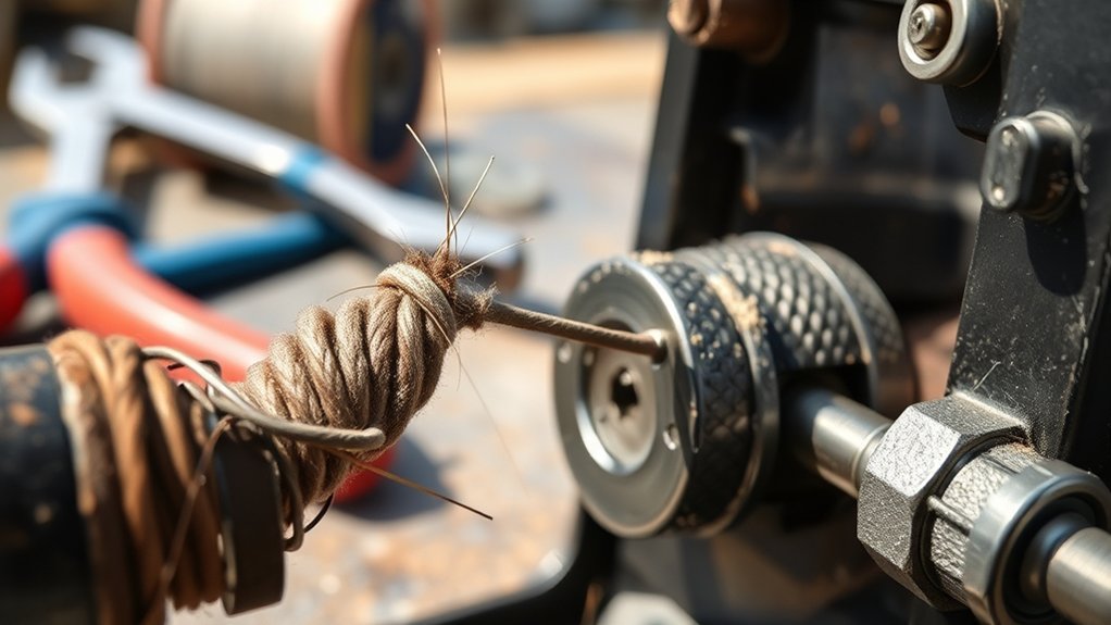
- Before each use: Inspect the gun cable, power cord, work lead, spool, wire, rolls, and visible connections.
- When feed becomes rough: Remove the contact tip, straighten the cable, and check for liner drag before adding more roll pressure.
- At spool changes: Vacuum or wipe metallic dust from the feed compartment with the machine unplugged.
- As needed: Clean the liner only by the method and air pressure allowed by the gun manual.
- When changing wire size or type: Verify the drive roll groove, liner range, contact tip, polarity, and process settings.
- During setup: Use the machine chart or manual for wire speed and voltage; do not use extreme settings to compensate for a mechanical feed restriction.
Step-by-Step MIG Wire Feed Troubleshooting Checklist
- Read the model manual: Confirm the correct wire size, roll groove, polarity, contact tip, liner range, and reset or thermal-protection behavior.
- Check basic power and settings: Make sure the machine is on, the input supply is correct, and wire speed is above zero.
- Let an overheated machine cool: Clear blocked air openings and stay within the rated duty cycle.
- Inspect the spool: Check wire direction, crossed wraps, rust, kinks, hub drag, and overrun.
- Inspect and clean the drive area: Match the groove, seat the wire correctly, and remove shavings or dust with the machine unplugged.
- Set minimum effective roll pressure: Increase only until the wire feeds steadily.
- Remove the contact tip: Straighten the cable, point the gun safely away, power the machine, and test the feed. Turn the machine off again before continuing.
- Inspect the tip: Clean or replace a blocked, wrong-size, enlarged, oval, overheated, or damaged tip.
- Check the liner and gun cable: Look for hard spots, kinks, contamination, wrong sizing, and incorrect trim length.
- Check the gun connection and trigger: Reseat accessible plugs and inspect for visible damage with power disconnected.
- Escalate electrical faults: If the rolls still do not turn, use an authorized service facility for fuse, board, motor, or internal wiring diagnosis.
Note: If wire feeds smoothly with the contact tip removed, replace or correct the tip before touching the liner or motor. If it feeds only with the cable straight, the liner or cable path is the stronger suspect.
When to Stop and Get Professional Service
Stop troubleshooting and contact a qualified technician when you see burned wiring, damaged insulation, a cracked gun connector, repeated fuse failure, smoke, a strong electrical odor, major physical damage, or a motor that receives power but will not turn. Also get service when the manual requires live-voltage testing that you are not trained to perform.
Do not bypass a thermal switch, fuse, interlock, or ground connection. Those devices protect the machine and operator.
Frequently Asked Questions
Why is my welder turning on but not feeding the wire?
Check that wire speed is above zero and the machine is not in thermal shutdown. Watch the drive rolls while pressing the trigger. Silent rolls point to the trigger, gun connection, control, fuse, or motor. Turning rolls point to spool drag, roll tension, a mismatch, or a downstream blockage.
How do I reset a MIG welder?
There is no universal reset. Turn the machine off, disconnect input power if you are inspecting it, and follow the model manual. If thermal protection has activated, let the welder cool with its vents clear; many machines restore output automatically after cooling.
How do I test a MIG wire feeder?
Remove the contact tip, straighten the gun cable, set wire speed above zero, point the gun away from people, and press the trigger while watching the rolls. If the rolls turn but the wire does not move, inspect the spool, groove, pressure, liner, and tip. If the rolls stay still, check power, thermal protection, trigger, and service items.
How do I adjust wire feed tension on a MIG welder?
Follow the machine manual. In general, start low and increase pressure only until the wire feeds smoothly without slipping. Deep roll marks, flattened wire, or metal shavings mean the pressure is too high or the groove is wrong.
Why does my MIG wire birdnest at the feeder?
Birdnesting usually means the rolls are still pushing while the wire is blocked farther downstream. Check the contact tip, liner, gun-cable bends, gun inlet alignment, roll type, and excessive roll pressure. Soft aluminum wire is especially prone to buckling in an unsuitable push system.
Why does my MIG wire burn back into the tip?
Burnback occurs when the arc reaches the wire end faster than fresh wire arrives. Check for a blocked or worn tip, low or interrupted wire feed, liner drag, excess cable bending, and settings that do not match the wire and material. Replace a fused or damaged tip before testing again.
Why do the drive rolls turn but the wire does not move?
The rolls may be in the wrong groove, too loose, dirty, or worn. The spool brake may also be too tight, the wire may be crossed on the spool, or the wire may be blocked at the tip or liner. Do not solve a blockage by continually adding pressure.
Why does the wire feed only when the gun cable is straight?
That pattern strongly suggests excess friction in the liner or a damaged cable. Inspect for kinks, contamination, an incorrect liner size, or a liner that was trimmed improperly. Replace a damaged liner rather than using more drive roll pressure.
Conclusion
A MIG welder that will not feed wire usually has a correctable problem in the wire path. Begin with the spool, drive rolls, pressure, gun cable, liner, and contact tip. Use the symptom to isolate the fault, match every consumable to the wire, and avoid forcing wire through a restriction. When the rolls remain silent after basic checks, move to model-specific trigger and service diagnostics with the machine safely disconnected.
Sources
- Lincoln Electric Handy MIG Operator’s Manual — wire loading, roll and tip matching, tension, thermal protection, maintenance, and electrical safety.
- Miller: Welding Aluminum vs. Steel — drive roll selection, pressure, and aluminum feed-system differences.
- Miller: Choosing MIG Welding Consumables — liner sizing, liner cleaning, contact tip wear, and wire-feed reliability.
- Bernard and Tregaskiss: Proper MIG Gun Liner Installation — liner trim length, installation, and birdnesting prevention.
- ESAB: Aluminum MIG Wire Feedability — spool, roll, liner, torch, and contact-tip considerations for soft wire.
- OSHA: Welding, Cutting, and Brazing Hazards and Solutions — electrical shock, burns, eye hazards, fumes, and PPE.




